1. Introduction
Cemented filler is a synthetic, multi-phase composite material composed of the cementing agent, filling aggregate, and mixing water. The cemented filling technology of tailing sand as filling aggregate realizes zero discharge of tailing sand. It is the mainstream way of underground mine filling. The study of the mechanical properties of tailing sand cemented fill is the basis for designing the filling strength and constructing the fill [
1,
2,
3,
4,
5]. However, in the actual downhole filling process, it is challenging to fully fill the extraction area at one time. The discontinuity of the filling operation causes delamination of the filling body at the interface between two fills, and the structural properties of the delamination will cause the mechanical properties of the filling body to change. Cao Shuai [
6] studied the strength reduction of layered cemented fillings with different concentrations and filling times and analyzed that the low-strength interlayer was the cause of the strength reduction of layered cemented fillings. Yanan Tang [
7] studied the compressive strength, elastic modulus, and crack evolution law of the layered cemented filler by changing the intermediate layer’s height ratio with the help of PFC software. Zhao Kang [
8] investigates the mechanical properties of the assemblies of cemented filling materials with different ash–sand ratios for the delamination phenomenon and analyzes the coordinated deformation mechanisms using acoustic emission characteristics. Wang et al. [
9] combined acoustic emission and digital image correlation techniques to investigate interfacial roughness and angle effects on gangue colloidal fillings’ damage evolution.
In the existing studies of layered cemented fillings [
10,
11,
12,
13,
14,
15], there are fewer studies on the interlayer dip angle of layering, which is an essential mechanical parameter affecting the strength of layered rocks; the dip angle of layering in this type of rock structure of fillings also affects its strength and damage form. Influenced by the inclination angle, the longitudinal and transverse deformation and strength of the layered layers have different expressions [
16,
17,
18], with apparent inclination angle effects; their damage mechanism and mode are different from other rock bodies.
In order to improve the adverse effects of layering and optimize the mechanical properties of the filler, this study introduces the sandblasting method used in concrete science to treat the interface between old and new concretes and applies it to the roughening of the layered surface of the filler [
19,
20,
21]. At the same time, sand, which is common and inexpensive in mine production, was chosen instead for the treatment so that it could serve to link the upper and lower layered surfaces. In this study, the mechanical properties of the tailing sand cemented fill specimens with two types of layering, natural layering and sandblasting layering, were investigated at different dip angles and different maintenance ages by simulating the actual filling conditions in the field. In addition, a damage model of the layered cemented filler was constructed to determine the mechanical properties of the filler under different layered dip angles and to provide a theoretical basis and technical guidance for the actual filling construction.
2. Materials and Methods
The tailing sand used in this test was selected from the whole tailing sand discharged from the iron ore processing plant of Crooked Head Mountain of Anshan Steel Group. The tailing sand collection method was selected from cross-layout shallow surface sampling, which follows the requirements of industry specifications. Meanwhile, the samples were measured in the geotechnical laboratory of the Liaoning University of Engineering and Technology.
2.1. Materials
The relative density of the tailing sand was measured to be 2.91, which is slightly larger than 2.6–2.7 of general geotechnical materials. The plastic limit is 15.8%, and the liquid limit is 24.2%; the plasticity index is 8.4, close to 7–10 of the available sandy soil material [
22].
Figure 1 shows the particle distribution curve of the tailing sand. Analysis of the curve data shows that 8.56% of the tailing sand is smaller than 20 microns, the average particle size of the tailing sand is 165.53 microns, the inhomogeneity coefficient Cu is 6.07, and the curvature coefficient Cc is 1.94, indicating that the tailing test sand has a broad particle size distribution and reasonable gradation.
Table 1 shows the chemical composition of the tailing sand, and the data indicate that the tailing sand used in this test is of high-silica type.
2.2. Experimental Method
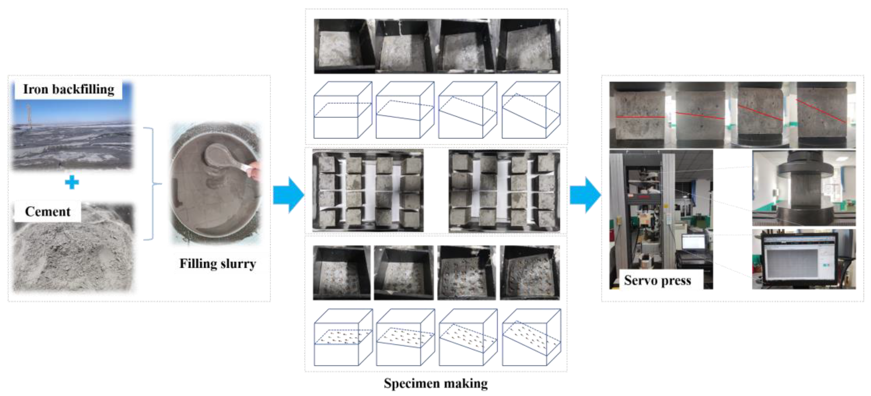
In order to improve the adverse effects of delamination, this test refers to the method of joining old and new interfaces in the concrete science-sandblasting method, which roughens up the delamination interface while acting as a joining interface and compares the effect of interface treatment, or lack thereof, on the mechanical properties of the delaminated cemented filler. In the test, we used a spring-loaded device to sandblast the delamination interface. The grit chosen was river sand with a 2 mm to 5 mm particle size. It was uniformly distributed to reduce the effect of sandblast thickness and density on the delamination interface. Set ash–sand ratio was 1:4, the slurry mass concentration was 76%, interlayer dip angles were 0°, 10°, 20°, and 30°; specimens were prepared by 70.7 mm × 70.7 mm × 70.7 mm triplex test mould; each dip angle contains two groups of delamination types for control, natural delamination and sandblasting treatment delamination. Constant temperature and a humidity maintenance box for maintenance were adopted, temperature (20 ± 2) °C, relative humidity (95 ± 5)%.
The detailed production process of the filled specimen is described as follows. (1) Slurry preparation: cement, tailing sand, and water are mixed in a set proportion and stirred well. (2) Mould filling: layered filling body two times filling, the first filling height of about 3 mm above the middle line, placed on the pre-adjusted angle of the carrier plate, the filling slurry will self-level into the pre-set carrier plate inclination, and knocking and shaking the mould to reduce the bubbles inside the slurry, the second filling to the standard height of the test mould, and the carrier plate placed horizontally, filling interval of 12 h, interface sandblasting treatment placed in the first filling after 6 h (slurry has certain plasticity). The gravel is not entirely embedded in the sublevels, which improves the roughness of the sublevels while linking the upper and lower parts. (3) Demoulding and maintenance: put the moulded specimens into the maintenance box and set up 3 d, 7 d, 14 d, and 28 d batches to take out the specimens for the uniaxial compression test. The uniaxial compression tests carried out on layered, filled specimens with different maintenance ages were conducted under a CMT5205 microcomputer-controlled electro-hydraulic servo press, with loading carried out by controlled displacement at a rate of 0.2 mm/min, and the computer would automatically record the stress–strain curve during the loading process, which was finally output in Excel format.
Figure 2 shows the test procedure.
3. Results
3.1. Uniaxial Compression Test Results
In order to study the effect of interlayer dip angle on the mechanical properties of the tailing sand cemented fill, we designed four kinds of interlayer dip angles, four kinds of maintenance and two types of stratification ages of the tailing sand cemented fill specimens in this test, a total of 32 groups, with the standard of three specimens in each group, a total of 96 specimens for uniaxial compression test. According to the univariate criterion, the average value of each group of measurements was used as the test result data at that level, and
Table 2 shows the uniaxial compression test results of the specimens.
3.2. Damage Model Construction
Damage is the deterioration of the macroscopic mechanical properties of the material or structure caused by the sprouting and expansion of acceptable structural defects (such as microcracks and microporosity) under the action of an external load or environment [
23,
24]. Compared with the intact filled specimens in ideal condition, the layered structural characteristics of the layered cemented filled body, i.e., the soft layered surface can be regarded as the initial damage; the uniaxial compression test is a continuous damage process under external loading, and the stress–strain curve is a direct reflection of this process, and it is of excellent research significance to construct an intrinsic damage model of the layered cemented filled body to predict its stress–strain curve.
The doctrine of strain equivalence indirectly defines the damage state of the material, i.e., the strain of the damaged material is equivalent to the strain caused by the effective stress acting on the practical part of the material [
25], and the concept of damage variables is introduced, then the principal damage equation of the cement-filled body is
where
is the damage variable of the glued filling body. Considering the layered structural surface as the initial damage of the filling body, denoted as
, assuming that the uniaxial compression process, the damage mechanism of the layered cemented filling body conforms to the Weibull model distribution [
26], and remembering the filling body damage evolution law in uniaxial compression as
, then
satisfies the distribution function of the Weibull model, that is
where
is the value that satisfies this distribution parameter,
and
are the Weibull distribution parameters of the material. From this, the damage instanton equation of the layered cemented filler is obtained as
We are substituting the strain
into
and associating the stress–strain curve to obtain the boundary conditions.
where
is the peak stress,
is the strain corresponding to the peak stress, the result of the joint solution of all kinds and substitution to obtain.
As shown in Equation (6), the intrinsic damage model of the layered cemented filling is related to the elastic modulus , the peak stress , and the strain corresponding to the peak stress.
4. Discussion
4.1. Compressive Strength of Layered Cemented Filler
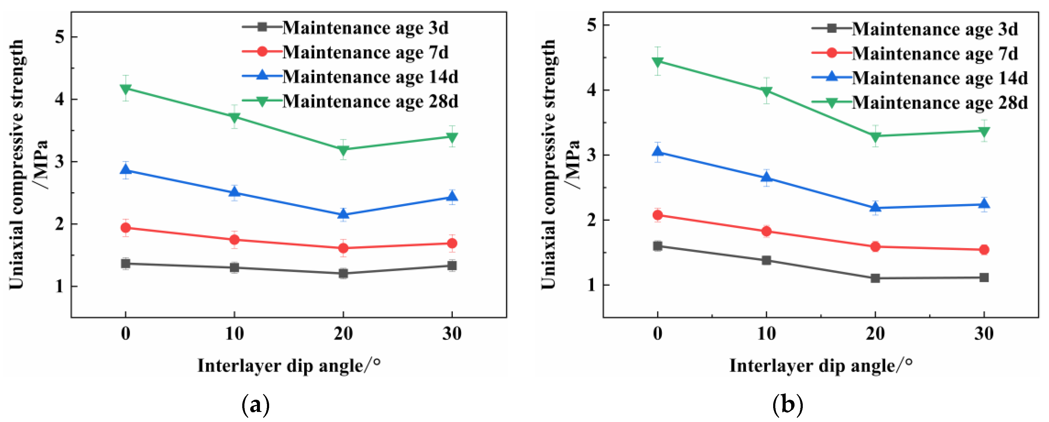
Figure 3 shows the uniaxial compressive strength curves for different interlayer inclination angles based on the data in
Table 2. Observing the change magnitude of each curve, the distribution pattern of the filling strength with the change of inclination angle is not apparent when the maintenance ages are 3 d and 7 d. The influence of the interlayer inclination angle on the filling strength increases gradually with the maintenance age. Comparing
Figure 3a,b, it is found that the uniaxial compressive strength of sandblasted delaminated specimens and natural delaminated specimens, influenced by different interlayer inclinations, are the same trend; both show the characteristics of the inflection point, the uniaxial compressive strength decreases with the increase of inclination between the interlayer inclination 0° and 20° and increases with the increase of inclination between the inclination 20° and 30°. However, the increase of sandblasted delaminated specimens compared with the natural delamination specimen is not apparent: the maximum increase is only 0.08 MPa. It is not difficult to find that the strength of the filling body at each maintenance age is the lowest at an inclination angle of about 20°. According to the research on the mechanical properties of laminated rocks by domestic and foreign scholars: the minimum value of compressive strength of laminated rocks is generally in the range of 20° to 60° of the angle between the maximum principal stress and the direction of the level [
27,
28,
29], which varies according to the lithology. Therefore, it is judged that the minimum compressive strength of the tailing sand colluvial fill used in this test occurs near the interlayer dip angle of 20° under the influence of natural delamination.
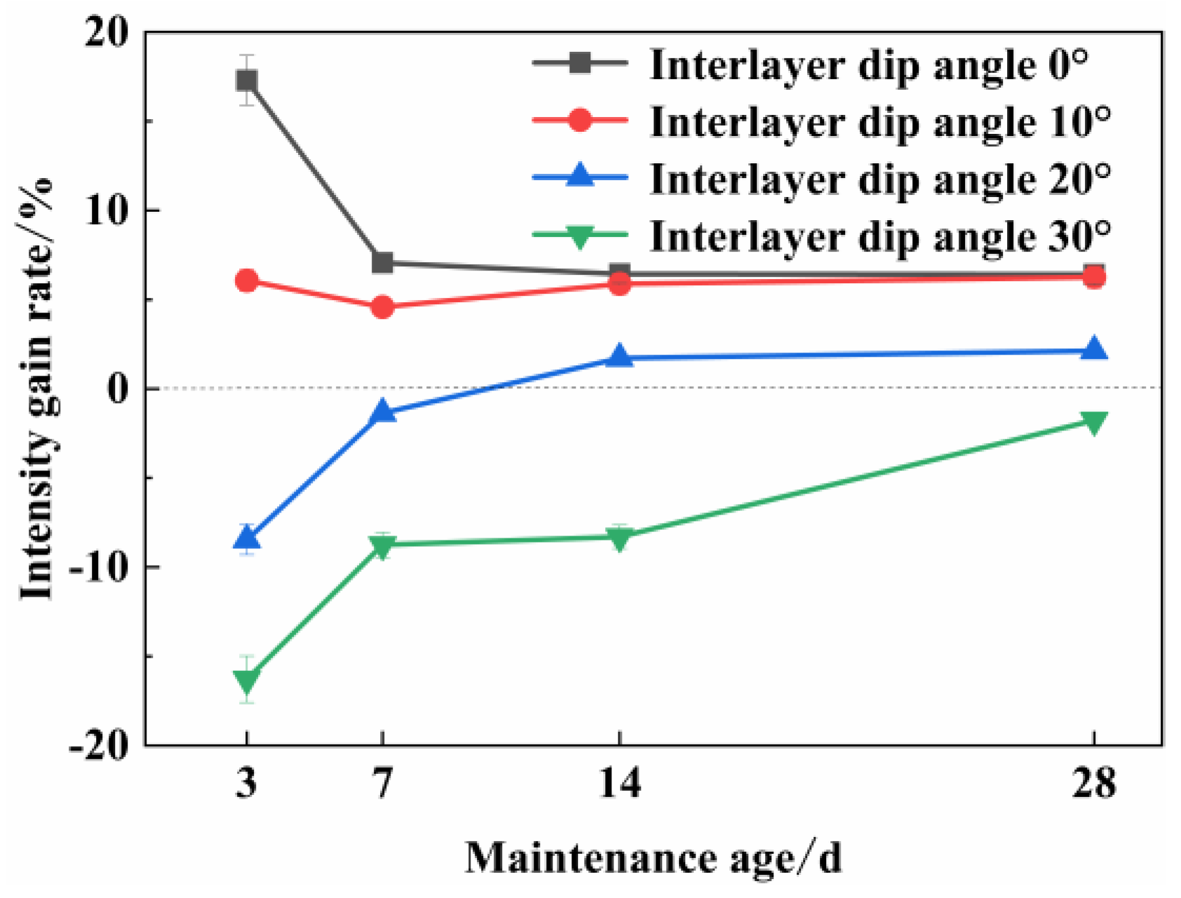
To quantify the effect of sandblasting treatment delamination on uniaxial compressive strength, define the strength gain rate.
where
is the strength gain rate;
is the compressive strength of naturally delaminated specimens (Mpa);
is the compressive strength of sandblasted delaminated specimens (Mpa).
Figure 4 shows the variation pattern of strength gain rate with interlayer dip angle and arranged in the order of maintenance age. Overall, the four curves from left to right gradually tend to be concentrated from dispersion. It indicates that the hydration reaction is incomplete at the early maintenance stage [
30], and the link between the sand and gravel on the layered surface and the filler is not tight. In contrast, the mechanical properties of the filler are weak, and the benefits brought by sandblasting treatment are magnified. In the uniaxial compressive test, when the interlayer dip angle is 0°, the sublevel is in the same direction as the primary stress, the more voids caused by the early age are continuously compacted, and the sand and gravel are combined with the filler to improve its uniaxial compressive strength. With the growth of interlayer dip angle, the angle between the principal stress direction and the sublevel keeps increasing, coupled with the shorter maintenance age leading to more voids existing around the sand and gravel, and thus subject to the increased partition force along the sublevel direction; hence, the voids that can be considered as initial damage will continue to expand along the sublevel direction while compacting. In addition, the non-tightly connected gravel slides in the direction of the sublevels causing damage; thus, reducing the mechanical properties of the filler to the extent that the early gain rate is negative at interlayer dips of 20° and 30°. With increased curing age, the strength gain rate tends to be concentrated and stabilized. The sandblasted treated layered surface at 28 d can give a positive gain in uniaxial compressive strength to the layered, filled specimens with an interlayer inclination angle of less than 20°.
4.2. Modulus of Elasticity of Layered Cemented Fillers
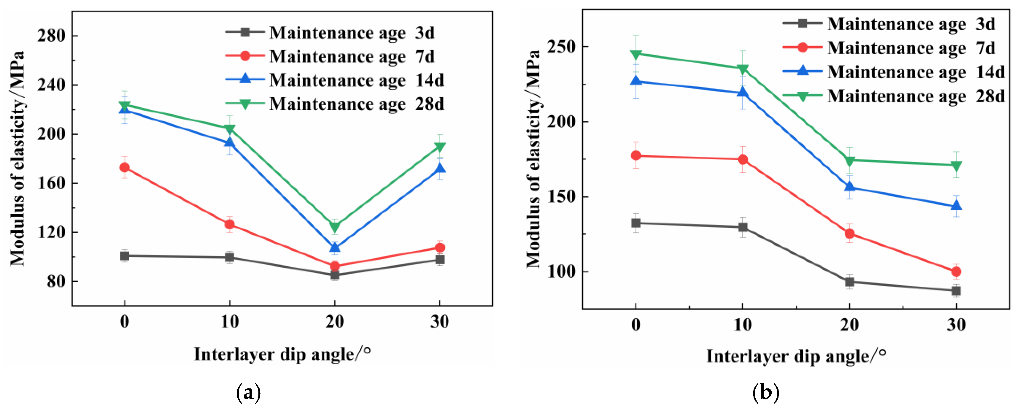
The relationship between the interlayer dip angle and the elastic modulus of the naturally layered filled specimens in
Figure 5a shows a similar trend to its strength. The lowest point of the elastic modulus appears near the dip angle of 20°. Comparison analysis of
Figure 5b in the sandblasting treatment under the conditions of different interlayer inclination angle change law, in the interlayer inclination angle of 20°, did not appear prominent inflection point characteristics; the elastic modulus in the interlayer inclination angle from 20° to 30° in the process of showing the trend of reducing. On the whole, with the increase of interlayer inclination angle, the elastic modulus of sandblasted delaminated specimens showed the law of phase decrease, which remained basically flat or slightly decreased in the process of interlayer inclination angle from 0° to 10° and from 20° to 30°. In comparison, the minimum decrease in the process of interlayer inclination angle from 10° to 20° was as high as 36.40 Mpa (maintenance age 3 d). It is easy to see from the two figures’ fold line direction that the sandblasting treatment delamination level changed the natural delamination exhibited by the delamination characteristics; especially, the natural delamination in the interlayer dip angle of 20° for the weakest dip angle change.
To quantify the effect of sandblasting delamination on the modulus of elasticity, define the modulus of elasticity gain rate.
where
is the elastic modulus gain rate;
is the compressive strength of naturally delaminated specimens (MPa);
is the compressive strength of sandblasted delaminated specimens (MPa).
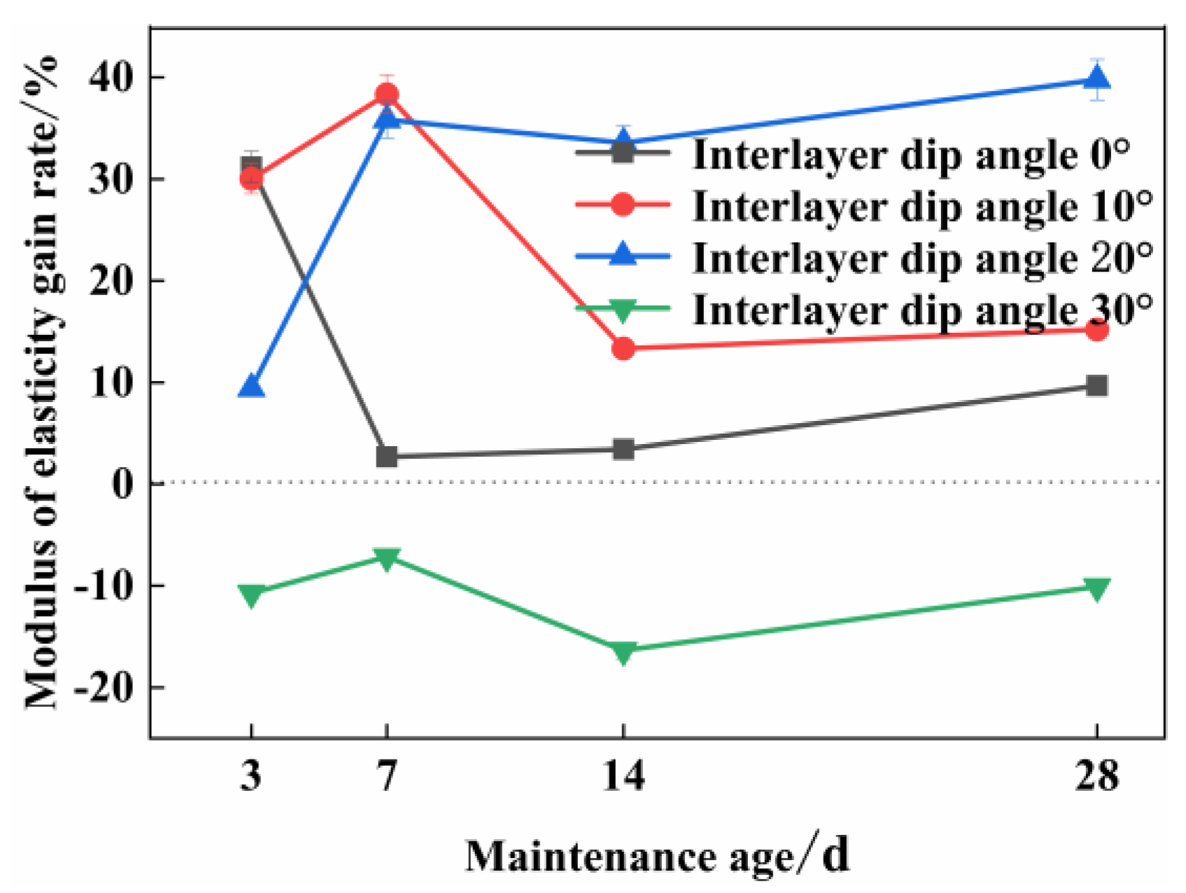
Figure 6 shows the variation pattern of elastic modulus gain rate with interlayer dip angle arranged in the order of maintenance age. Overall, with the development of the maintenance age, the gain rate is affected by the change of the inclination angle and gradually shows a stable trend. The data in the figure shows that the sandblast-treated sublevels can give the highest elastic modulus gain rate of 39.78% at an interlayer dip angle of 20° at the high age when the mechanical properties of the filler are more stable. This also corroborates with the results in
Figure 5b, where the interlayer inclination angle of 20° is no longer the weakest point for specimens with sandblasted sublevels. The sandblasting treatment brings positive elastic modulus gain to the filled specimens with an interlayer inclination angle of less than 20°.
4.3. Post-Peak Ductility of Layered Cemented Fillers
Post-peak ductility is the level of compressive strength that the specimen can maintain at the same strain during the yielding phase after the peak strength. To study the effect of interlayer dip angle on the post-peak ductility, we selected specimens with a maintenance age of 28 d for analysis.
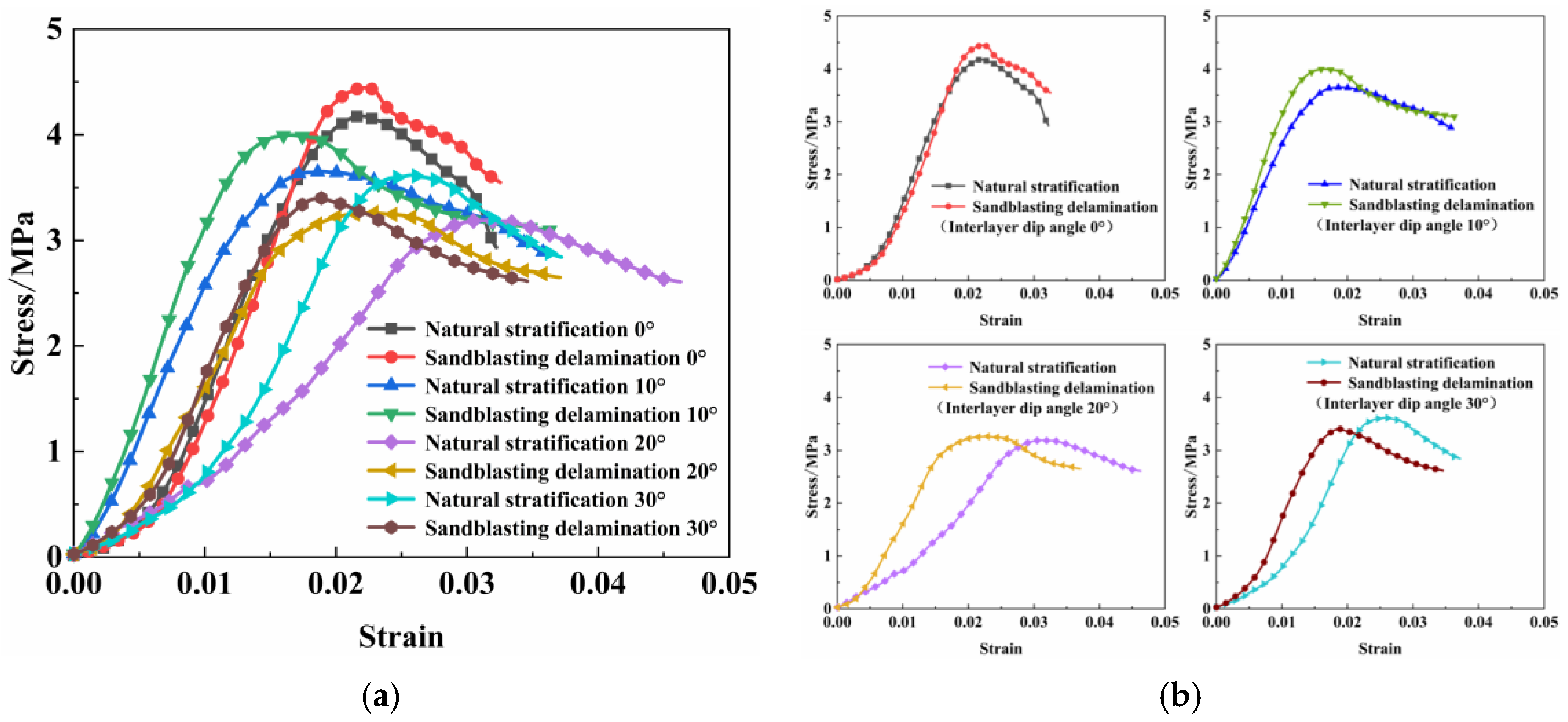
Figure 7 shows the stress–strain curves. Using the rate of decline of the post-peak strength curve as the evaluation criterion of ductility, the measured and calculated natural layered specimens at interlayer inclination angles of 0°, 10°, 20°, and 30° showed a decrease in strength of 1.149 MPa, 0.365 MPa, 0.355 MPa, and 0.709 MPa, respectively, within 1% strain after reaching the peak strength. The corresponding post-peak ductility showed a pattern of increase and then decrease with the increase of inclination angle. The corresponding post-peak ductility showed a changing pattern with the increase of the inclination angle, and the optimum ductility was reached at an inclination angle of about 20°. In comparison, the post-peak ductility of the two specimens at the inclination angles of 10° and 20° were closer. Comparative measurements showed that the strength of sandblasted delaminated specimens decreased by 0.881 MPa, 0.658 MPa, 0.474 MPa, and 0.586 MPa within 1% strain after reaching peak strength at interlaminar inclination angles of 0°, 10°, 20°, and 30°, respectively. The optimum ductility was reached at an interlaminar inclination angle of about 20°. Although the sandblasting treatment improved the post-peak ductility only at interlayer inclination angles of 0° and 30°, the overall sandblasting treatment sublevels did not change the variation pattern of increasing and then decreasing with the inclination angle. The optimum ductility was maintained at the interlayer inclination angle of about 20°.
4.4. Destruction Forms of Layered Cemented Fillers
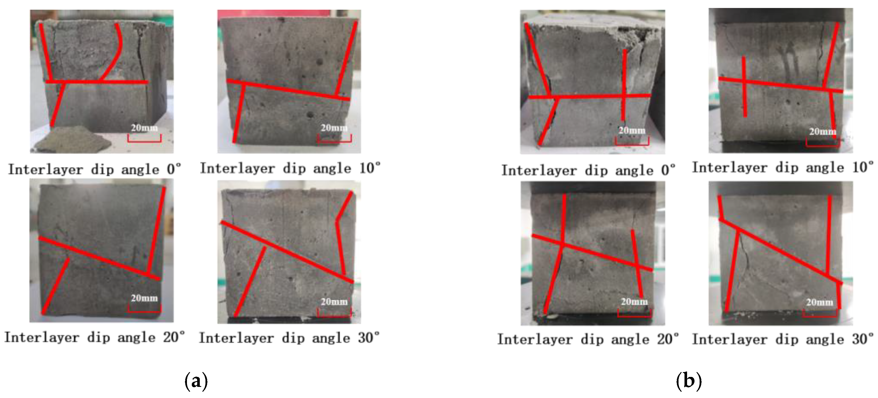
To analyze the damage forms caused by different interlaminar dip angles, we selected a representative post-damage specimen from each test group and displayed it in
Figure 8. We observe the damaged form of the naturally layered filled specimens in
Figure 8a. The layered, filled bodies under the influence of interlayer inclination angle all show the characteristics of conjugate shear damage, the direction of the maximum principal stress changes with the change of inclination angle, and the cracks are mainly concentrated in the layered layer and the direction of the maximum principal stress. The upper part of the layered filling specimen shows an apparent delamination phenomenon. The upper part of the filling near the loading end shears conjugately, and the vertical compressive stress gradually transforms into a part of the horizontal tensile stress through the delamination level. The upper and lower delamination damage surface has a certain degree of misalignment along the delamination level. The misalignment phenomenon becomes more evident with the inclination angle increase, and the conjugate shear damage is accompanied by secondary tensile shear damage. A comparative analysis of the damage forms of the sandblasted delaminated filled specimens in
Figure 8b shows both tensile damage forms through the delamination level and conjugate shear damage forms. Comprehensive analysis shows that the damage form of the layered filling body is mainly manifested as tensile damage and conjugate shear damage, the layered layer makes part of the vertical compressive stress transformed into horizontal tensile stress, and the cracks inside the specimen are concentrated in the soft layered layer, thus reducing the compressive strength of the filling body. The sandblasted-layered layer improves the transmission mode of the upper and lower layered force to some extent.
4.5. Validation of Damage Intrinsic Model
The appearance of interlayer dip angle causes the misalignment of the upper and lower parts of the filler, so it is necessary to verify whether the layered cemented filler with different dip angles conforms to the intrinsic damage model. The mechanical properties of the filling specimens tend to stabilize after 28 d of maintenance age, so in order to reduce the test error, the test data with 28 d of age and interlayer inclination angles of 0°, 10°, 20°, and 30° were selected.
Table 3 shows each specific principal structure model.
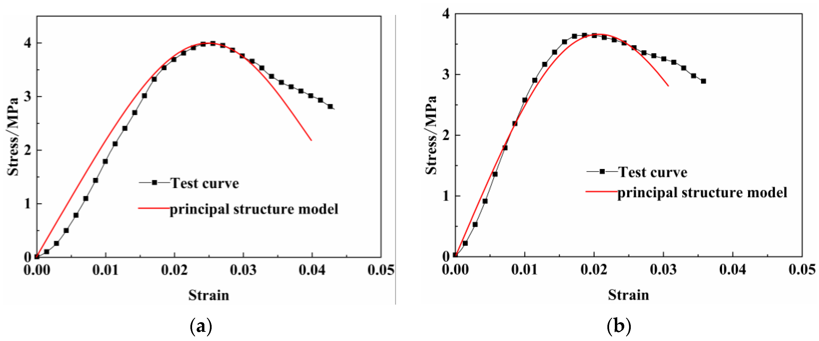
The stress–strain curves obtained from the intrinsic damage model and the test are plotted in
Figure 9, and it is not difficult to find that the intrinsic model and the test curve maintain the same trend. Among these
Figure 9a,b, the test curves overlap with the intrinsic model in the pre-peak stress phase. However, the two overlap poorly in the post-peak phase, while
Figure 9c,d show the opposite state, with a poor overlap in the pre-peak phase and a good overlap in the post-peak phase. This situation before the peak stress is since the initial pore compacting phase inside the filler, i.e., the “upward concave” phase shown in the first part of the stress–strain curve, is not considered in constructing the intrinsic model. The phenomenon that the curve of the principal model is lower than the test curve after the peak stress is due to the idealized assumption of damage of the principal model, i.e., the cavity inside the material that cannot carry the load. In contrast, the specimen in the actual test can still bear the load after the damage, showing post-peak ductility. Overall, the damage intrinsic model can predict the stress–strain curve of the tailing sand colluvium filling body more accurately and has high reliability for different interlayer dips, providing a theoretical basis and technical guidance for the actual filling construction.
5. Conclusions
(1) The uniaxial compressive strengths of sandblasted-layered specimens and naturally layered specimens both showed a trend of decreasing and then increasing with the increase of interlayer dip angle, reaching a minimum at an interlayer dip angle of about 20°, showing a naturally similar to that of layered rocks, and the effect of interlayer dip angle on the strength of the filler gradually increased with the increase of the maintenance age. At high curing age, sandblasting treatment of sublevels can give positive gains in uniaxial compressive strength to the filled body specimens with an interlayer dip angle not more significant than 20°.
(2) The relationship between the interlayer inclination angle and the elastic modulus of the naturally layered filled specimens shows a similar trend to their strength, with the lowest point of the elastic modulus appearing near the inclination angle of 20°. The modulus of elasticity of sandblasted-layered specimens shows the law of phase decrease, and the interlayer inclination angle of 20° is no longer the weakest point. The sandblasted-layered specimens can give a positive gain in the modulus of elasticity for the interlayer inclination angle not more significant than 20°. Moreover, it reaches the highest at the interlaminar inclination angle of 20°, 39.78%.
(3) Using the rate of decrease of the post-peak strength curve as the evaluation criterion of ductility, the post-peak ductility of both sandblasted delaminated specimens and natural delaminated specimens showed a change law of increasing and then decreasing with the increase of inclination angle. The optimum ductility was reached at an inclination angle of about 20°. The sandblasting treatment can improve the post-peak ductility at the interlayer inclination angles of 0° and 30°.
(4) The layered filling body’s damage form mainly manifests as tensile damage and conjugate shear damage. The layered level makes the vertical compressive stress part into horizontal tensile stress. The internal specimen cracks in the soft layered concentration, thus reducing the compressive strength of the filling body. Sandblasting treatment of layered, to a certain extent to improve the transmission of the upper and lower layered force engineering in order to cut the layered on the deterioration of the mechanical properties of the material, can be in the second filling interval of the last filling surface for sandblasting and other roughing treatment.
(5) Based on the damage evolution of soil based on Weibull distribution, we constructed a damage ontology model of layered cemented fill under the premise that the layered structure is regarded as the initial damage of the fill and verified that the stress–strain curve predicted by the model is highly coincident with the test curve. Its reliability is high for different interlayer dip angles, which can provide a theoretical basis and technical guidance for actual fill construction.
Author Contributions
Conceptualization, L.H. and R.B.; methodology, L.H.; validation, L.H.; formal analysis, R.B.; investigation, R.B.; resources, L.H.; data curation, R.B.; writing—original draft preparation, R.B.; writing—review and editing, L.H. and R.B.; visualization, R.B.; supervision, L.H.; project administration, L.H.; funding acquisition, L.H. All authors have read and agreed to the published version of the manuscript.
Funding
This research was conducted with financial support from the National Natural Science Foundation of China (NSFC) project (52274084), funded by the Natural Science Foundation of China.
Institutional Review Board Statement
Not applicable.
Informed Consent Statement
Not applicable.
Data Availability Statement
The datasets used and/or analysed during the current study are available from the corresponding author upon reasonable request.
Conflicts of Interest
The authors declare no conflict of interest.
References
- Fu, J.; Du, C.; Song, W. Strength sensitivity and failure mechanism of full tailings cemented backfills. J. Univ. Sci. Technol. Beijing 2014, 36, 1149–1157. [Google Scholar]
- Qiao, D.; Cheng, W.; Xie, J.; Wang, J.; Huang, F.; Mo, Y.; Peng, J. Analysis of the influence of gradation on the strength of a cemented filling body and the cementation strength model. Integr. Ferroelectr. 2019, 199, 12–21. [Google Scholar] [CrossRef]
- Sari, M.; Yilmaz, E.; Kasap, T.; Guner, N.U. Strength and microstructure evolution in cemented mine backfill with low and high pH pyritic tailings: Effect of mineral admixtures. Constr. Build. Mater. 2022, 328, 127109. [Google Scholar] [CrossRef]
- Cheng, A.P.; Dai, S.Y.; Zhang, Y.S.; Huang, S.; Ye, Z. Study on size effect of damage evolution of cemented backfill. Chin. J. Rock Mech. Eng. 2019, 38, 3053–3060. [Google Scholar]
- Yang, L.; Hou, C.; Zhu, W.; Liu, X.; Yan, B.; Li, L. Monitoring the failure process of cemented paste backfill at different curing times by using a digital image correlation technique. Constr. Build. Mater. 2022, 346, 128487. [Google Scholar] [CrossRef]
- Cao, S.; Song, W.; Xue, G.; Wang, Y. Tests of strength reduction of cemented tailings filling considering layering character. Rock Soil Mech. 2015, 36, 2869–2876. [Google Scholar]
- Tang, Y.; Fu, J.; Song, W.; Zhang, Y. Mechanical properties and crack evolution of interbedded cemented tailings backfill. Chin. J. Eng. 2020, 42, 1286–1298. [Google Scholar]
- Zhao, K.; Huang, M.; Yan, Y.J.; Wan, W.L.; Ning, F.J.; Zhou, Y.; He, Z.W. Mechanical properties and synergistic deformation characteristics of tailings cemented filling assembled material body with different cement-tailings ratios. Chin. J. Rock Mech. Eng. 2021, 40, 2781–2789. [Google Scholar]
- Wang, Y.; Wu, J.; Pu, H.; Chen, W.; Yin, Q.; Yang, S.; Ma, D. Effect of interface geometric parameters on the mechanical properties and damage evolution of layered cemented gangue backfill: Experiments and models. Constr. Build. Mater. 2022, 349, 128678. [Google Scholar] [CrossRef]
- Wei, X.M.; Li, C.H.; Zhang, L.X. The ratio parameter design and engineering optimization of high stage delayed cemented backfill. J. Min. Saf. Eng. 2017, 34, 580–586+593. [Google Scholar]
- Liu, G.S.; Yang, X.C.; Guo, L.J. Models of three-dimensional arching stress and strength requirement for the backfill in open stoping with subsequent backfill mining. J. China Coal Soc. 2019, 44, 1391–1403. [Google Scholar]
- Wang, J.; Song, W.; Cao, S.; Tan, Y. Mechanical properties and failure modes of stratified backfill under triaxial cyclic loading and unloading. Int. J. Min. Sci. Technol. 2019, 29, 809–814. [Google Scholar] [CrossRef]
- Hou, Y.; Yin, S.; Cao, Y.; Yang, S.; Zhang, M. Stress-Strain Relationship and Damge Constitutive Model of Cemented Tailings Backfill under Uniaxial Compression. Mater. Rep. 2022, 36, 179–186. [Google Scholar]
- Qi, C.; Guo, L.; Wu, Y.; Zhang, Q.; Chen, Q. Stability Evaluation of Layered Backfill Considering Filling Interval, Backfill Strength and Creep Behavior. Minerals 2022, 12, 271. [Google Scholar] [CrossRef]
- Yan, R.F.; Liu, J.M.; Yin, S.H.; Zou, L.; Kou, Y.Y.; Zhang, P.Q. Effect of polypropylene fiber and coarse aggregate on the ductility and fluidity of cemented tailings backfill. J. Cent. South Univ. 2022, 29, 515–527. [Google Scholar] [CrossRef]
- Le, A.D.; Nguyen, T.S. Hydromechanical response of a bedded argillaceous rock formation to excavation and water injection. Can. Geotech. J. 2015, 52, 1–17. [Google Scholar] [CrossRef]
- Spyropoulos, E.; Nawaz, B.; Ojo, A.; Ahmed, H.R.; Waheed, M.A. Stability assessment of obliquely-bedded rock cuts using multi-prong procedures—Case study. IOP Conf. Ser. Earth Environ. Sci. 2021, 833, 012042. [Google Scholar] [CrossRef]
- Ju, M.; Li, J.; Li, J.; Zhao, J. Loading rate effects on anisotropy and crack propagation of weak bedding plane-rich rocks. Eng. Fract. Mech. 2020, 230, 106983. [Google Scholar] [CrossRef]
- Zhao, Z. Research on Bonding Mechanism of New and Old Concrete and Its Engineering Application; China Water & Power Press: Beijing, China, 2003. [Google Scholar]
- Zhang, J. Concrete Science; Harbin Institute of Technology Press: Harbin, China, 2011. [Google Scholar]
- Fang, Z.; Wu, R.; Pei, B.; Jiang, Z. Size Effect of the Shear Performance on the Bonding Interface between New and Old Concrete. China J. Highw. Transp. 2021, 34, 92–103. [Google Scholar]
- Ministry of Housing and Urban-Rural Development of the People’s Republic of China; State Administration for Market Regulation. GB/T50123-2019; Standard for Geotechnical Testing Method. China Planning Press: Beijing, China, 2019.
- Kabir, H.; Hooton, R.D.; Popoff, N.J. Evaluation of cement soundness using the ASTM C151 autoclave expansion test. Cem. Concr. Res. 2020, 136, 106159. [Google Scholar] [CrossRef]
- Mehta, P.K. History and status of performance tests for evaluation of soundness of cements. In Cement Standards—Evolution and Trends; ASTM International: West Conshohocken, PA, USA, 1978. [Google Scholar]
- Lemaitre, J. How to use damage mechanics. Nucl. Eng. Des. 1984, 80, 233–245. [Google Scholar] [CrossRef]
- Roy, A.; Chakraborty, S.; Kundu, S.P.; Basak, R.K.; Majumder, S.B.; Adhikari, B. Improvement in mechanical properties of jute fibres through mild alkali treatment as demonstrated by utilisation of the Weibull distribution model. Bioresour. Technol. 2012, 107, 222–228. [Google Scholar] [CrossRef]
- Tien, Y.M.; Tsao, P.F. Preparation and mechanical properties of artificial transversely isotropic rock. Int. J. Rock Mech. Min. Sci. 2000, 37, 1001–1012. [Google Scholar] [CrossRef]
- Serrano, A.; Olalla, C. Ultimate bearing capacity of an anisotropic discontinuous rock mass. Part I: Basic modes of failure. Int. J. Rock Mech. Min. Sci. 1998, 35, 301–324. [Google Scholar] [CrossRef]
- Gholami, R.; Rasouli, V. Mechanical and Elastic Properties of Transversely Isotropic Slate. Rock Mech. Rock Eng. 2014, 47, 1763–1773. [Google Scholar] [CrossRef]
- Schutter, G. Fundamental study of early age concrete behaviour as a basis for durable concrete structures. Mater. Struct. 2002, 35, 15–21. [Google Scholar] [CrossRef]
| Disclaimer/Publisher’s Note: The statements, opinions and data contained in all publications are solely those of the individual author(s) and contributor(s) and not of MDPI and/or the editor(s). MDPI and/or the editor(s) disclaim responsibility for any injury to people or property resulting from any ideas, methods, instructions or products referred to in the content. |
© 2023 by the authors. Licensee MDPI, Basel, Switzerland. This article is an open access article distributed under the terms and conditions of the Creative Commons Attribution (CC BY) license (https://creativecommons.org/licenses/by/4.0/).


