Article

An Arch-Bridge Topology-Based Expressway Network Structure and Automatic Generation

1
School of Mechanical Engineering and Automation, Huaqiao University, Xiamen 361021, China
2
Fujian Key Laboratory for Automotive Electronics and Electric Drive, Fujian University of Technology, Fuzhou 350118, China
*
Authors to whom correspondence should be addressed.
Appl. Sci. 2023, 13(8), 5031; https://doi.org/10.3390/app13085031
Submission received: 14 March 2023 / Revised: 6 April 2023 / Accepted: 11 April 2023 / Published: 17 April 2023
(This article belongs to the Section Earth Sciences)

Abstract

:
The rapid generation and automatic updating of road network topology information have immense practical significance and application value for intelligent expressways. Therefore, this work proposes a novel arch-bridge topology based on an electronic toll collection (ETC) system to redefine the structure of the expressway network. On this basis, discrete ETC data generate corresponding trajectories according to the arch-bridge topology structure, and an initial topology candidate set is generated. Furthermore, the characteristics of abnormal topologies, such as loop, reverse, missing, and opposite topologies, are deeply explored and analyzed, and targeted constraint conditions are designed to optimize the initial topology candidate set. Finally, experiments and evaluations are conducted on transaction data collected from an ETC system in a certain province of China. The experimental results show that the proposed method is practical and has significant results in terms of evaluation metrics and efficiency. Specifically, the recall, precision, and F1 are 0.982, 0.966, and 0.974, respectively. Additionally, it takes less than 2 ms on average to generate one topology. The proposed method can efficiently and accurately generate the topology information of an entire expressway network.

1. Introduction

As of the end of 2021, China’s expressway mileage reached 169,100 km, ranking first in the world [1]. Currently, China’s expressway electronic toll collection (ETC) system has achieved interconnectivity across 29 provinces [2]. Over 27,000 sets of ETC gantries have been installed, 48,000 ETC lanes have been renovated, and the total number of ETC users in the country has surpassed 250 million. As one of the world’s largest Internet of Vehicles (IoV) systems, the ETC system undertakes daily non-stop toll collection for tens of thousands of vehicles and the clearing of expressway tolls in various provinces, accumulating a significant amount of ETC transaction data. Both domestic and foreign researchers are gradually conducting intelligent expressway research based on these data, including travel time estimation [3,4,5], traffic situation estimation [6,7,8,9], visualization of traffic demand [10], identification of maximum speed limit information [11], automatic generation of ETC gantry position [12], abnormal data detection [13], etc. It is evident that research on intelligent expressways based on big ETC data mining is gaining momentum as a new research hotspot.
The ETC gantry topology, as the most important network topology information of the ETC system, is not only the underlying foundation of the entire intelligent transportation system but also the key to the expansion of application services based on ETC data mining. However, the ETC gantry topology of expressways is not immutable; for example, the permanent addition or removal of roads or road maintenance causes permanent changes in the network topology and sudden events cause temporary changes in the network topology. Therefore, it is of great practical significance and application value to quickly generate and automatically update road network topology information for the service of intelligent expressways.
The traditional method of extracting road network information mainly relies on professional surveyors driving road-measuring vehicles equipped with GPS devices for on-site measurement [14]. This method suffers from serious problems [15], such as long information acquisition cycles, high workload, and high cost, making it difficult to meet the travel needs of hundreds of millions of people in China. With the rapid development of advanced technologies such as big data mining and image recognition in recent decades, numerous domestic and foreign research scholars have conducted extensive research on the generation of road network information and obtained a batch of phased achievements, making the automatic generation of road network topology information possible. Currently, road network topology generation methods can be divided into two categories based on different data sources: remote sensing image recognition and spatiotemporal trajectory mining.
Remote sensing image recognition mainly uses remote sensing images as data sources and, through a series of image recognition methods, such as restricted Boltzmann machine and convolutional neural network, extracts road areas, centerlines, and edges and other information to achieve the automatic recognition of road network topology information [16,17,18,19,20,21,22,23,24,25,26,27,28,29,30,31,32,33,34,35]. However, remote sensing image recognition has drawbacks, such as large computational complexity, complex remote sensing image backgrounds, and easy occlusion, and ETC gantries are very similar to traffic sign gantries, which can cause confusion. On the other hand, spatiotemporal trajectory mining mainly uses GPS trajectory data as data sources and employs big data mining methods such as clustering and map matching to extract and update road network information [36,37,38,39,40,41,42,43,44,45,46,47,48,49,50,51,52,53,54,55,56,57,58]. This is also the main method used in this study. However, unlike urban roads, expressways have long road sections and wide spans, and small-sample floating cars cannot achieve full-domain coverage, resulting in a severe lack of data for some road sections. Therefore, there is an urgent need to develop a method that can quickly generate the entire domain road network topology of expressways.
To address the aforementioned challenges, we conducted research on the ETC system in a province of China with a user penetration rate exceeding 80%, meaning that over 80% of the vehicles on the expressway were using the ETC service. Specifically, we proposed a novel arch-bridge topology-based expressway network structure. Furthermore, by conducting in-depth mining analysis of ETC data features and designing candidate topology optimization rules, we could achieve the rapid automatic generation of the entire domain road network topology of expressways. Theoretical analysis and experimental results show that our method has good robustness. In addition, based on the expressway network topology structure of the ETC system, real-time monitoring of all sample vehicle information can be achieved, making it possible to finetune the management of expressways.
The main contributions of this study are as follows:
(1)
We proposed a novel arch-bridge topology structure with ETC gantries as key nodes, which can simplify the complex road network topology to the smallest unit by redefining the topology of expressways.
(2)
Through deep mining and the analysis of ETC data characteristics, we designed excellent optimization rules for targeted anomalous topologies such as loop, reverse, missing, and opposite topologies.
(3)
The validity of the proposed method is verified by using real ETC transaction data with a user penetration rate of over 80%, which can achieve the effective and cost-effective generation of the entire domain of an expressway road network topology.
The remaining parts of this work are organized as follows. In Section 2, we first review relevant research on road network topology generation. In Section 3, we provide relevant definitions. In Section 4, we introduce the candidate topology generation and optimization method. In Section 5, we conduct experiments and analyze the results. Finally, we give the conclusion of this work and look forward to future research.

2. Literature Review

2.1. Remote Sensing Image Recognition Method

Research on generating road networks based on remote sensing images can be categorized into semi-automatic and automatic methods depending on the degree of human intervention [16]. In the semi-automatic approach, seeds are typically the center points or contours of road segments, and are manually provided or verified after extraction. On the other hand, the automatic method involves adjusting parameters based on different source images before the program starts, and the subsequent process does not require human intervention. In the earlier days of computer vision, bottom-up processes such as stereo matching and motion tracking required advanced knowledge to correctly interpret low-level events. To address this challenge, Kass et al. [17] proposed the snake model, which defines an energy function on the user-defined image contour and iteratively adjusts the energy minimum to converge the image contour. The snake model has been widely adopted in various fields of computer vision and has also been introduced into the research on semi-automatic road network generation based on remote sensing images [18,19,20]. Additionally, the snake model can solve the problem of road image noise and large gaps between roads [21]. Some scholars have also incorporated dynamic programming methods. Gruen and Li [22] proposed a semi-automatic road extraction scheme that combines wavelet decomposition for road sharpening with a model-driven linear feature extraction method based on dynamic programming. Based on this research, Poz and Do Vale [23] introduced road width into the metric function, which can be utilized for road network extraction in remote sensing images. Furthermore, Wegner et al. [24] automatically estimated seeds using the maximum road probability, connected seeds using the minimum cost path, and constructed a road network through mixed integer programming, thereby resolving the problem of low efficiency due to human intervention.
Although the semi-automatic method has achieved some results, the manual intervention mode greatly increases the time cost. Therefore, many scholars are also exploring automatic methods for extracting road networks. Artificial neural networks are complex network structures composed of a large number of neurons, which are an abstract simulation of the human brain mechanism that developed rapidly after the introduction of backpropagation. Mokhtarzadeh and Zoej [25] proposed a method for road detection from high-resolution satellite images using artificial neural networks and found the best network structure by verifying the impact of different input parameters on the network’s ability. Based on this, some scholars have improved the road and background detection capabilities of neural networks by adding different combinations of texture and spectral parameters during road extraction based on an artificial neural network classifier [26]. Support vector machines (SVMs) are a type of linear binary classifier that assigns one of two possible labels to a given test sample. SVMs are particularly attractive in remote sensing because they have good generalization ability, even with limited training samples [27]. Yager and Sowmya [28] first used Support Vector Machines (SVMs) to extract roads from remote sensing images based on road edges, achieving high completeness but relatively low accuracy. Based on this, Mirnalinee et al. [29] combined support vector machines with the output of differential matrices to extract roads more accurately.
In recent years, the rapid improvement of GPU performance has facilitated the wide application of deep learning techniques in road network generation. Mnih and Hinton [30] pioneered the use of deep learning techniques for this purpose, proposing a method that utilizes restricted Boltzmann machines (RBMs) to detect road areas from high-resolution aerial images. Following their lead, Saito et al. [31] proposed a single convolutional neural network multi-channel prediction method for patch-based aerial image semantic segmentation, achieving improved prediction performance with the softmax function as an activation function. In the field of medical image processing, Ronneberger et al. [32] developed the U-Net model to segment biological microscope images, achieving good performance across various domains [33]. Building on the success of the U-Net model in medical image processing, Diakogiannis et al. [34] proposed a residual U-Net for extracting road information from remote sensing images, incorporating the characteristics of encoder–decoder residual units to enhance performance. Building on this approach, Sultonov et al. [35] introduced two lightweight models that incorporate deep separable convolution and ConvMixer initial blocks into the encoder–decoder architecture of U-Net. The experiments demonstrate that these models can accurately extract road networks with fewer parameters.

2.2. Spatio-Temporal Trajectory Mining

With the continuous development of GPS sensor technology, it has become easier to obtain vehicle GPS trajectory data with higher accuracy and richer feature information. As a result, many researchers have turned to using GPS trajectory data for road network generation. Currently, there are three main methods for road network generation based on GPS trajectory data: (1) point clustering, (2) kernel density estimation (KDE), and (3) cross-linking.
Point clustering involves using clustering algorithms (such as k-means) to extract the edges and basic points of the road network from GPS sampling points, and then connecting these elements to form a road network. In early research, Wagstaff et al. [36] attempted to identify road networks based on low-precision GPS data. They used a k-means algorithm with background knowledge constraints to cluster GPS tracking data from vehicles to find lanes. In subsequent work, the same authors proposed a spatial clustering algorithm that could infer map connectivity structure from scratch, making the map refinement process completely independent of the initial input map. This more powerful lane clustering algorithm can handle lane segmentation and merging [37]. Edelkamp and Schrodl [38] used the Bentley-Ottmann algorithm to convert GPS data into a graphical structure and then applied k-means clustering to identify lanes. Worrall S and Nebot E [39] applied clustering algorithms to mining environments, successfully identifying road networks even without clear road edges or lane markings. Chen et al. [40] developed a Traj-Meanshift algorithm to denoise GPS points and an innovative graph-based road segment clustering algorithm that utilized prior information on road smoothness. A point clustering method based on DBSCAN was also used for map matching [41]. Huang et al. [42] used the advancing front spatial clustering with Delaunay triangulation (ASCDT) method to perform spatial clustering and combined spatial semantic information to construct road structure and topological relationships.
The kernel density estimation (KDE) method is commonly used for visualizing and analyzing spatial data, with the aim of understanding and potentially predicting event patterns [43]. Nowadays, researchers have also applied KDE in road network generation, where it first transforms individual samples or trajectories into a discretized image that represents the density of samples or segments at each pixel. Using binary thresholds, they produce a binary image of the roads within the area and find the centerline of the roads through various methods, such as Voronoi partitioning. Uduwaragoda et al. [44] utilized non-parametric kernel density estimation to analyze the probability density distribution of trajectory points and generate an improved map containing lane centerlines. Kuntzsch et al. [45] combined heuristic techniques, using KDE aggregation to obtain road segments between intersections, with generation modeling to reconstruct the optimal road map. Neuhold et al. [46] employed KDE to determine the lane centerlines of three types of roads, using low-precision GPS data collected by floating vehicles as input. Fu et al. [47] utilized kernel density analysis to estimate trajectory density, evaluating the results of centerline extraction with a hidden Markov model and eliminating erroneously extracted road centerline segments. They then employed a road centerline thinning method and map matching algorithm to incrementally merge road centerlines to generate a road network. This method exhibits good robustness and does not require additional parameter tuning.
The intersection connection method is a technique used to construct and update road networks. It involves detecting intersection vertices and connecting them with edges based on trajectory features such as direction and speed. The intersections are then identified by interpolating the geometric shapes of the trajectories. Fathi and Krumm [48] were among the first to use this method to construct maps. Karagiorgou and Pfoser [49] developed a heuristic algorithm that “bundles” trajectories around intersection nodes. Xie et al. [50] defined intersections as locations where three or more road segments connect in different directions and used LCSS to detect common sub-trajectories of multiple GPS trajectories. Later, they employed image processing techniques [51] to skeletonize binary trajectory matrices and detect local “sub-paths,” ultimately identifying intersections using KDE. Wu et al. [52] proposed a novel intersection detection algorithm based on improved X-means, which was used to identify road network intersections in Shenyang, China. Huang et al. [53] used prior knowledge of intersection types and turning restrictions to detect road segments. Deng et al. [54] proposed a point clustering method based on hotspot analysis and triangulation to detect intersection coverage, generating a structural model using K-segment fit and common subsequence merging. Pu et al. [55] developed a two-stage framework for road intersection detection called RIDF, consisting of trajectory quality improvement and intersection extraction. Zhao et al. [56] were the first to calibrate the topological impact area of road intersections and proposed a three-stage calibration framework called CITT. Qing et al. [57] presented a GPS-based road intersection detection method that improves accuracy by extracting spatiotemporal features and leveraging their interactions. Liu et al. [58] proposed an intersection detection approach based on the xDeepFM model and DBSCAN algorithm, which is a density-based noise-aware spatial clustering method.

3. Methodology

3.1. Arch-Bridge Topology

In the ETC system, OBUs (onboard units) are mounted onto vehicles and RSUs (roadside units) are mounted onto the roadside. Through DSRC (dedicated short-range communication) technology, they communicate with each other to collect all relevant information about passing vehicles. In other words, the expressway network uses ETC gantries as key nodes that can collect information from all vehicles in the entire area and all samples. However, according to the “ETC gantry system technical requirements for expressways” issued by the Ministry of Transport in 2019 [59], ETC gantries are deployed not only at the entrances and exits of each toll station but also on road sections before changes in traffic flow occur, such as entrance/exit ramps and interchanges. Of course, this is significantly different from the traditional expressway road network structure, i.e., intersections as nodes. As shown in Figure 1, red triangles are used to mark expressway intersections. However, in the current practical situation, the expressway intersection as a node cannot obtain all passing vehicle information, which makes it difficult to realize the fine management of the expressway.
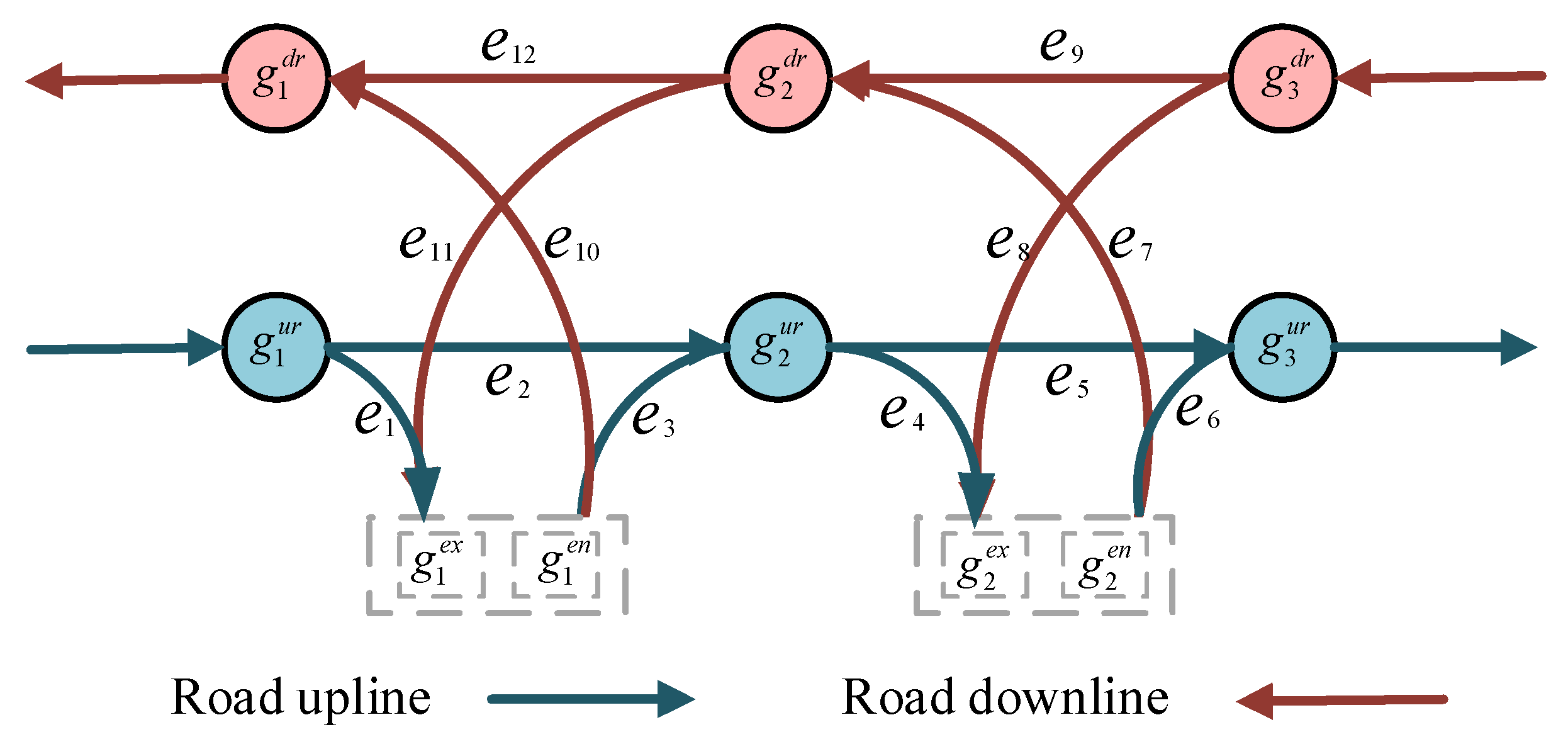
Therefore, we propose a new type of expressway network structure based on the ETC system. The road network is composed of a set of ETC gantry nodes deployed on sections of the road with two-way traffic, denoted as G r = g 1 u r , g 1 d r , g 2 u r , g 2 d r , , g n 1 u r , g n 1 d r , a set of gantry entrance station (including cross-provincial entrances) nodes denoted as G e n = g 1 e n , g 2 e n , , g n 2 e n , and a set of gantry exit station (including cross-provincial exits) nodes denoted as G e x = g 1 e x , g 2 e x , , g n 2 e x , etc., forming a key node set G = G r G e n G e x (the total number of nodes n = 2 × (n1 + n2)) and a set of road sections S = s 1 , s 2 , , s m formed by the nodes. Each road section is represented as s i = g s t a r t , g e n d   S , i = 1 , 2 , 3 , m , where g s t a r t G r G e n and g e n d G r G e x are the two key nodes of the road network, representing the starting and ending nodes of the road section s i , respectively. Figure 1 shows a simple expressway network, where there are four entrance/exit gantry station nodes g 1 e n , g 2 e n , g 1 e x , g 2 e x and six ETC gantry nodes g 1 u r , g 1 d r , g 2 u r , g 2 d r , g 3 u r , g 3 d r , forming a total of 12 road sections s 1 , s 2 , , s 12 .
From Figure 1, it can be observed that the expressway is a fully enclosed, multi-lane road that controls all entrances and exits and is divided into upline and downline lanes. The ETC gantries are deployed on adjacent (>30 m) upline and downline lanes. Of course, compared with the complex urban road network, the expressway network relying on the ETC system is more structured and organized. Therefore, based on the network topology construction method in complex network analysis, the roadside gantries and station entrance and exit gantries are abstracted as nodes, road sections are abstracted as edges, and a new type of arch-bridge topology structure is defined as follows:
Definition 1. 
Arch-bridge Topology: When an n-order graph  𝓖 = < G ,   E >   meets the following conditions, the graph   𝓖  is defined as an arch-bridge topology:
(1)
𝓖 is a directed graph, with the starting node G e n , the middle node G r , and the ending node G e x ;
(2)
There are pairs of paths: g 1 e n , g 1 u r , , g n 1 u r , g n e x and g n e n , g n 1 d r , , g 1 d r , g 1 e x .
Here, g i u r   and   g i d r respectively represent the gantry nodes deployed on the upline and downline lanes of the road, also known as mutually exclusive gantry pairs, denoted as ( g i u r g i d r ) .
As shown in Figure 2, this topology shape is similar to an arch-bridge; thus, it is named “arch-bridge topology.” The two adjacent toll stations and their intermediate ETC gantries on the upline and downline sections can form a minimal arch-bridge topology structure. Of course, the complex expressway network structure can be decomposed into simple arch-bridge topologies. Compared with traditional road network maps, the arch-bridge topology structure not only preserves the overall shape of the road network but also simplifies the complex road network structure, making the reconstruction of the entire expressway network traceable. To meet the needs of subsequent research, the following definition is given:
Definition 2. 
Node Degree: The number of gantry nodes directly adjacent to the gantry node   g i  is called the degree of the gantry node   g i , denoted as   π g i . Specifically, the number of gantry nodes directly connecting upline and downline to   g i   on the road are referred to as the in-degree   π i n g i   and out-degree   π o u t g i  of   g , respectively.
π g i = π i n g i + π o u t g i
Of course, for gantry station entrances (including provincial border entrance gantries), the gantry node g i has π i n g i = 0 , π o u t g i 1 , g i G e n ; for gantry station exits (including provincial border exit gantries), the gantry node g j has π i n g j 1 , π o u t g j = 0 , g j G e x ; the middle gantry g k has both in-degree and out-degree and π i n g k 1 , π o u t g k 1 , g k G r . According to the definition, given a mutually exclusive gantry pair ( g i g j ) , the in-degree and out-degree will have the following relationship:
π i n g i = π o u t g j
π o u t g i = π i n g j
Definition 3. 
Directed edge   e k = g i , g j E , formed by two nodes  g i , g j , has a distance denoted as the edge distance  d e k , which refers to the actual shortest path distance from node   g i  to node  g j .
Edge distances can be obtained by the Amap path planning API. Therefore, each edge in the edge set E of the expressway network graph 𝓖 corresponds to a unique edge distance, forming the edge distance set D. The edge distance set D can be used as a non-negative weight for the directed edges of graph 𝓖 , forming an expressway network distance-weighted graph 𝓖 D = < G ,   E ,   D > .
Definition 4. 
Edge flow is defined as the number of vehicles that pass through both nodes of a directed edge  e k = g i , g j E . It is denoted as  f e k .
Similarly, the edge flow set F can be used as a non-negative weight for the directed edges of graph G, forming an expressway network flow-weighted graph 𝓖 F = < G ,   E ,   F > . It is worth noting that edge flow directly reflects the importance of directed edges: the larger the edge flow, the greater the traffic load on that road segment, indicating a higher level of importance in the entire road network.
Definition 5. 
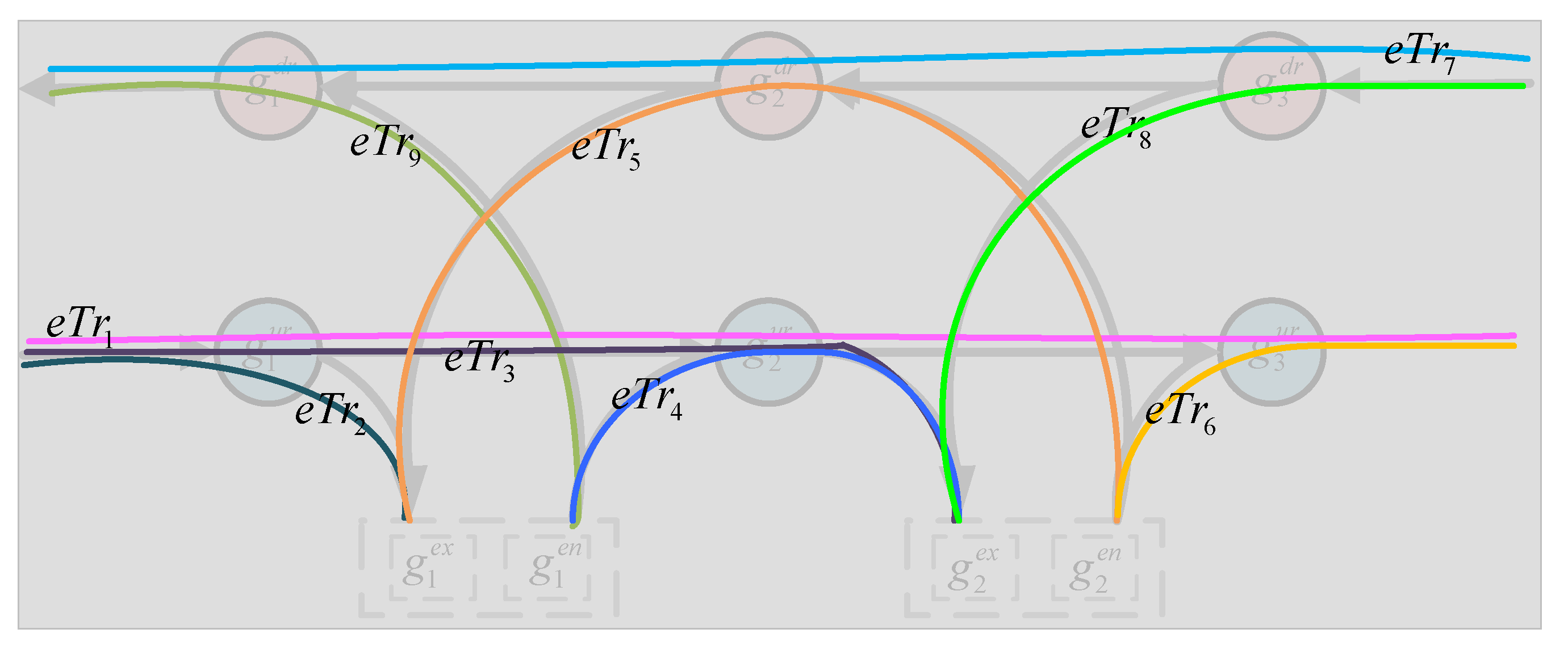
The trajectory of a vehicle passing through ETC gantries in a continuous time period on the expressway network is referred to as the ETC trajectory, denoted as follows:
e T r i d = g 1 , g 2 , , g n
here, g 1 and   g n are the starting and ending points of the trajectory, respectively, and id represents the unique travel number. The gantry position g i . p o s = l n g , l a t and the gantry type g i . t y p e 0 , 1 , 2 , 3 , 4 represent the toll station entrance gantry, provincial border entrance gantry, roadside gantry, toll station exit gantry, and provincial border exit gantry, respectively. Specifically, both the toll station entrance gantry and the provincial border entrance gantry are entrance gantries, which are the starting gantry of the ETC trajectory. Both the toll station exit gantry and the provincial border exit gantry are entrance gantries, which are the ending gantry of the ETC trajectory. The roadside gantry is installed at the expressway roadside, which is the middle gantry of the ETC trajectory. Other information, such as the gantry transaction timestamp g i . t g i + 1 . t g i . t , is also included, where n represents the length of the trajectory.
As shown in Figure 3, ETC travel trajectory data contain rich potential road network topology. Therefore, this work will delve into the characteristics of ETC travel trajectories and reconstruct the expressway network structure through spatiotemporal trajectory mining, as detailed in Section 4.

3.2. Automatic Generation of Expressway Network Topology

3.2.1. Topology Set Generation and Analysis

Given the ETC driving trajectory set e T R A J = e T r 1 , e T r 2 , , e T r m , the set of candidate topologies formed by adjacent trajectory points of all driving trajectories is called the candidate topology set c E = c e 1 , c e 2 , , c e n , c e i j = < g i , g j >     cE ,   g i G , g j G .
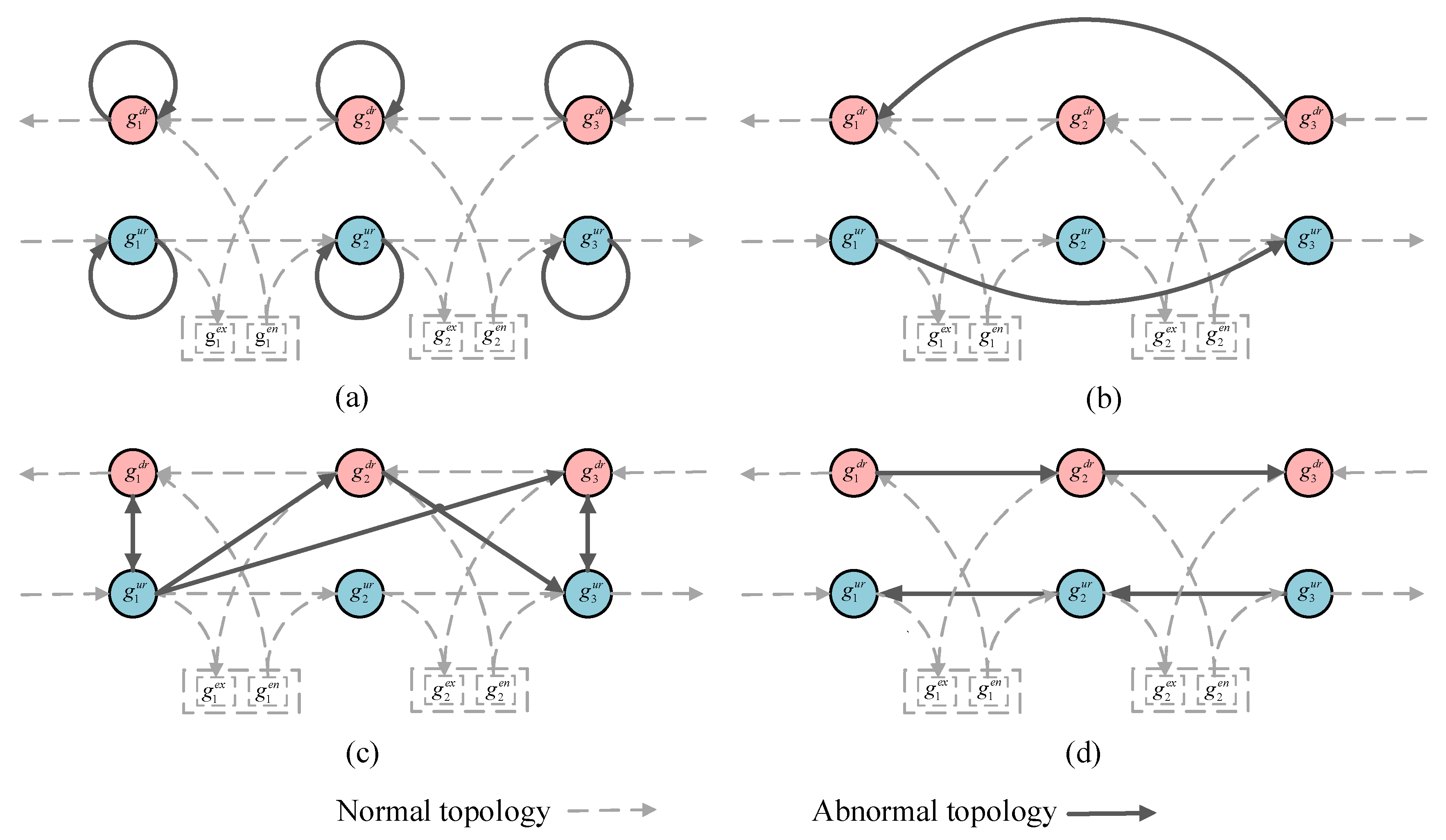
However, there is a large amount of “dirty” data in the ETC data, which causes many incorrect topologies in the candidate edge set cE and severely interferes with the reconstruction of the expressway network. There are mainly four aspects:
(1)
Generally, data is repeatedly uploaded during transmission or copied repeatedly during storage, which easily leads to an increase in data size and causes serious interference to the automatic generation of ETC topology. In addition, when traffic congestion, breakdowns, and other issues occur within the ETC gantry antenna coverage area, the vehicle-mounted OBU will continue to communicate with the ETC antenna, resulting in duplicate data collection. As shown in Figure 4a, abnormal topology forms a loop, referred to as a loop topology.
(2)
Due to equipment failures, severe weather conditions, etc., the vehicle-mounted device and the ETC antenna may not communicate or fail to communicate successfully, resulting in data loss. At the same time, packet loss may occur during data transmission, causing data loss. When n ≥ 3, there may be consecutive data loss, referred to as a missing topology, as shown in Figure 4b.
(3)
Due to wireless interference, the vehicle-mounted OBU driving on the road upline (downline) successfully communicates with the ETC antenna deployed on the road downline (upline), and the resulting topology is referred to as opposite topology record data that do not conform to the rules of expressway driving, as shown in Figure 4c.
(4)
Special vehicles such as police cars and emergency vehicles inevitably perform reverse driving when executing emergency or special tasks, resulting in and referred to as a reverse topology, as shown in Figure 4d.

3.2.2. Candidate Topology Set Optimization

We must clean up the abnormal topology mentioned in Section 4.1. Therefore, we need to conduct a detailed analysis of different types of abnormalities and design corresponding optimization rules.
(a)
Loop Topology Optimization
As shown in Figure 4a, data redundancy causes the formation of self-loops in the gantry nodes. However, according to actual expressway traffic rules, this type of candidate topology edge cannot exist. To solve this type of anomaly, it is obvious that we only need to directly delete the topologies with the same nodes from the topology candidate edge set cE to complete the cleaning. The following constraint conditions can be designed:
c E = { c e i j = g i , g j | g i ! = g j c e i j c E }
(b)
Reverse Topology Optimization
According to the different types of gantries on the expressway, there are three types of reverse topologies:
(1)
g i , g j , g i G r , g j G e n : From the gantry nodes on the road section to the gantry entrance nodes or province entrance gantry;
(2)
g i , g j , g i G e x ,   g j G r : From the exit gantry nodes or province exit gantry nodes to the normal gantry nodes on the road section;
(3)
g i , g j , g i ,   g j G r : From normal gantry nodes on the road section to normal gantry nodes on the road section.
According to Definition 2, the indegree of the gantry or nodes at the entrance of the province or gantry station is π i n g i = 0 , g i G e n . Of course, there is no topology from the normal gantry node to the entrance gantry node or provincial entrance gantry node. Similarly, the outdegree of exit gantry nodes at the province border exit gantry is π o u t g j = 0 , g j G e x , and there is also no exit gantry or provincial border exit gantry node to normal gantry node topology. Therefore, the following constraint condition can be designed:
c E = { c e i j = g i , g j | g i . t y p e 3 , 4 g j . t y p e 0 , 1 c e i j c E }
For the optimization method from normal gantry to normal gantry, please refer to part d.
(c)
Missing Topology Optimization
To address the issue of missing data, Figure 4b shows that in the distance-weighted graph 𝓖 D = < G ,   cE ,   D   > of the expressway network, except for the candidate edge c e i = g i , g j itself, if there exists a path p a t h = g k , g k + 1 , , g n , g k = g i , g n = g j , where g k = g i and g n = g j and the total accumulated distance of this path d p a t h = k = 1 n 1 d c e k k 1 is equal to the total distance of the candidate edge d c e i j , then the candidate edge c e i j is a redundant edge and can be directly deleted.
However, there may be multiple paths available between two gantry nodes in the expressway network, which we refer to as ambiguous paths. If we want to find all ambiguous paths between each pair of gantry nodes, the time and space complexity of the path search method will grow exponentially with the increase of gantry nodes, which is clearly impractical. As defined in Definition 3, the candidate edge distance d c e i j is the shortest mileage between two gantry nodes obtained through the Gaode map path planning API. Therefore, we only need to obtain the shortest one from all the ambiguous paths in the constructed distance-weighted graph 𝓖 D = < G ,   cE ,   D   > . Of course, this is a typical shortest-path problem.
Dijkstra’s method is a shortest-path method proposed by Dutch computer scientist Dijkstra in 1959 [60]. It solves the shortest path problem from one vertex to all other vertices and is exactly the problem we need to solve in a non-negative weighted graph. Therefore, this section will use Dijkstra’s method to obtain the shortest path between two gantry nodes from the distance-weighted graph 𝓖 D = < G ,   cE ,   D   > . The main feature of Dijkstra’s method is to start from the starting point and use the greedy strategy to traverse the adjacent nodes of the vertex closest to the starting point and not visit until the endpoint is reached. The specific steps are as follows:
  • Step 1: Calculate the distances D = d c e i j , i = 1 , 2 , 3 , , n }    for all candidate edge sets cE, and construct an expressway network distance-weighted graph 𝓖 D = < G ,   cE ,   D   > ;
  • Step 2: Set the starting point o and the ending point d, mark the starting point, and set all other nodes as unmarked. Let k = o, l o o = 0 , l o j = + , and p = [] be the predecessor array;
  • Step 3: Search for the node j directly connected to node k in the set of all unmarked nodes and calculate and update as follows:
    l o j = min l o j , l o k + d k j
If l o j is updated, set the predecessor of node j to k and update the predecessor array p;
  • Step 4: Obtain the node j * in the set J of all unmarked nodes that is closest to the starting point o:
    j * = arg min j J l o j
  • Step 5: Mark j * . If all nodes have been marked, the method exits; otherwise, update k = j * and go to Step 3.
Finally, obtain the p a t h = g k , g k + 1 , , g n , g k = g i , g n = g j ; the total accumulated distance of this route is d p a t h = k = 1 n 1 d c e k k + 1 . Therefore, in the case of missing transactions, the following constraint can be designed:
c E = { c e i j | d p a t h c e i j ! = d c e i j c e i j c E }
(d)
Opposite Topology Optimization
According to different opposite gantry configurations, erroneous transactions can be classified into three types:
(1)
g i , g i or g i , g i : erroneous transactions with the bidirectional gantry itself;
(2)
g i , g i + 1 or g i , g i + 1 : erroneous transactions with the bidirectional gantry of the next gantry g i + 1 , directly connected in the same direction as g i ;
(3)
g i , g i + n or g i , g i + n : erroneous transactions with the opposite gantry g i of the nth (n ≥ 2) gantry g i + n in the same direction as the gantry g i .
Except for the first case, the second and third cases involve not only erroneous but also missing transactions, which is called the erroneous and missing phenomenon. For example, in g 1 , g n , the erroneous transaction gantry is g n , and the missing transaction gantries are g 2 , , g n + 1 .
Of course, the first case involves mutually exclusive gantry node pairs ( g i u r g i d r ) , and the topology candidate edges formed by these gantry node pairs can be directly removed from the topology candidate edge set cE. The following constraint conditions can be designed:
c E = { c e i = g i , g j | g i g j c e i j c E }
where g i g j indicates that g i and g j are non-road up-down mutually exclusive gantry node pairs.
Specifically, in the initial stage of gantry planning and design, it is simple to mark the gantry numbers of mutually exclusive gantry node pairs with special labels, such as 349 E 61 359 E 61 , where the only difference in the gantry number is in the second character. Therefore, this type of constraint is relatively easy to handle.
Regarding the second and third types of erroneous trades (e.g., g 1 , g n or g 1 , g n ), they not only have the characteristic of erroneous trade but also of missed trade; thus, we need to use their characteristic of missed trade. A simple trick is to convert one of the gantries into its corresponding opposite gantry:
g 1 , g n =   transformer g 1 , g n
In this way, it can be transformed into a missing topology and then optimized using the Dijkstra method.
Specifically, according to Definition 2, π i n g i = 0 , g i G e n , π o u t g j = 0 , g j G e x , π i n g k 1 , π o u t g k 1 , g k G r , we can construct the following:
gce = { [ c e ij 1 , c e ij 2 , c e ij 3 , c e ij 4 , c e ij 5 , c e ij 6 , c e ij 7 , c e ij 8 ] , g i . t y p e = g j . t y p e = 2 [ c e ij 1 , c e ij 3 , c e ij 6 , c e ij 8 ] ,        g i . t y p e = 0 / 3 , g j . t y p e = 2 [ c e ij 1 , c e ij 4 , c e ij 5 , c e ij 8 ] ,        g i . t y p e = 2 , g j . t y p e = 1 / 4 [ c e ij 1 , c e ij 8 ] ,            g i . t y p e = 0 / 3 , g j . t y p e = 1 / 4
where c e i j 1 = g i , g j , c e i j 2 = g j , g i , c e i j 3 = g i , g j , c e i j 4 = g j , g i , c e i j 5 = g i , g j , c e i j 6 = g j , g i , c e i j 7 = g i , g j , c e i j 8 = g j , g i .
As can be observed from the above, by taking the shortest distance topology in gce , the missing topology can be obtained. We define this as follows:
c e ij * = arg min c e ij gce d c e ij
We can design the constraint conditions as follows:
c E = { c e i j * | d p a t h c e i j * ! = d c e i j * c e i j * c E }

4. Experiment and Results Analysis

The experimental platform utilized an Intel (R) Core (TM) i9-10900K CPU with 10 cores and a base clock of 3.70 GHz, along with 64 GB RAM. The experiments were performed on the CentOS Linux release 7 September 2009 (Core) operating system. Python 3.8.8 was the programming language used for development, while Jupyter Notebook, an open-source interactive computing environment, was employed for conducting and presenting the experiments. For more information about Jupyter Notebook, please refer to its official website (https://jupyter.org/), accessed on 1 October 2022.

4.1. Data Description

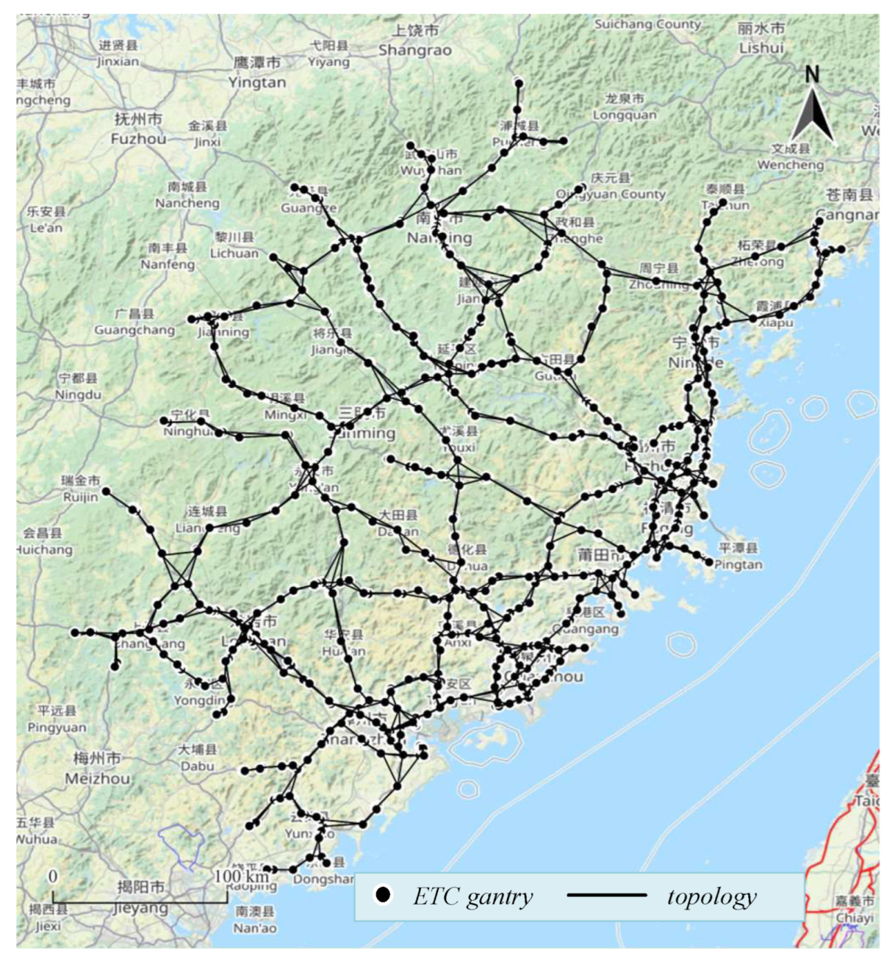
This article presents experimental data collected from the ETC system on a highway in a province in China from 1–5 June 2021. The province’s highway network has a total length of 6000 km and ranks third in China in terms of road density. There are more than 1000 ETC gantries and more than 2900 gantry topologies, as shown in Figure 5. The ETC transaction dataset comprises over 35 million records, including vehicle identifiers (after desensitized), transaction time, gantry number, and trip number, as shown in Table 1. The vehicles include four types of passenger cars, six types of freight vehicles, and six types of special-purpose vehicles, with a total of approximately 1.33 million vehicles.

4.2. Road Network Topology Coverage

Based on five days of ETC transaction data, we conducted sampling on different data volumes and counted the number of candidate topologies and topology coverage. Specifically, candidate topology refers to the total number of topologies formed by ETC driving trajectories after de-duplication, while topology coverage refers to the proportion of candidate topologies in the real road network topology. The formula for calculating topology coverage is as follows:
c o v e r a g e = C E g e n e C E o r i C E o r i
where C E g e n e is the set of candidate topologies and C E o r i is the set of original topologies; |*| indicates the total number of elements in a set.
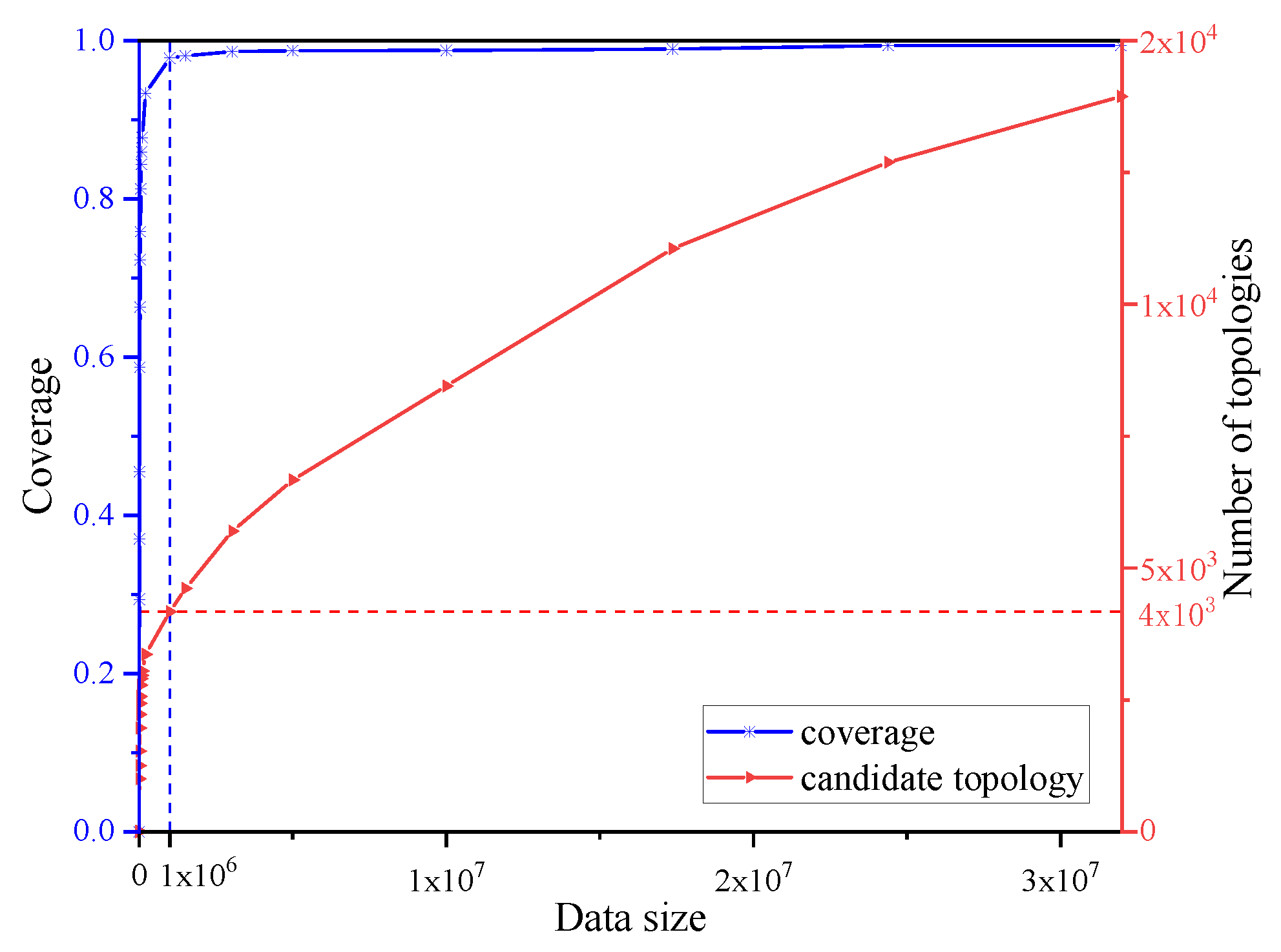
As shown in Figure 6, the fitted topology coverage curve shows a rapid upward trend as the data volume increases and then stabilizes after reaching 1 million, with the entire road network topology coverage exceeding 99%. In contrast, the trend of the total number of candidate topologies shows a continuous upward trend throughout the curve and still generates a large number of candidate topologies after the data volume reaches 1 million. Through a comparative analysis of the two curves, it is known that a data volume of 1 million is a watershed, and the vast majority of the candidate topologies generated after the data volume reaches 1 million are incorrect, which causes unnecessary interference to the subsequent road network reconstruction and seriously affects the efficiency of topology generation.

4.3. Evaluation of Road Network Topology Reconstruction

To evaluate the effectiveness of the proposed method, we compared the automatically generated road network topology with the actual topology of the expressway network and used precision and recall to quantify the evaluation. Specifically, the precision of the method is determined by the excess topology generated in the reconstructed topology, with fewer excess unmatched topologies indicating higher precision, as shown in the following formula:
p r e c i s i o n = 1 # F P # T P + # F P
where # T P and # F P indicate the number of correct topologies identified as correct topologies and the number of incorrect topologies identified as correct topologies in the generated topology set, respectively.
Likewise, the recall is determined by the number of unmatched topologies in the actual topology of the expressway network, with fewer unmatched topologies indicating higher recall, as shown in the following formula:
r e c a l l = 1 # F N # T P + # F N
where # F N indicates the number of unmatched topologies in the actual topology of the expressway network.
Precision and recall are conflicting measures. F1 is a comprehensive indicator calculated from precision and recall:
F 1 = 2 · r e c a l l · p r e c i s i o n r e c a l l + p r e c i s i o n
The F1 value ranges from 0 to 1, with a higher value indicating better performance in generating gantry topologies. When F1 is equal to 1, that is, when both recall and precision are equal to 1, this indicates that the topology of the expressway network has been fully reconstructed.
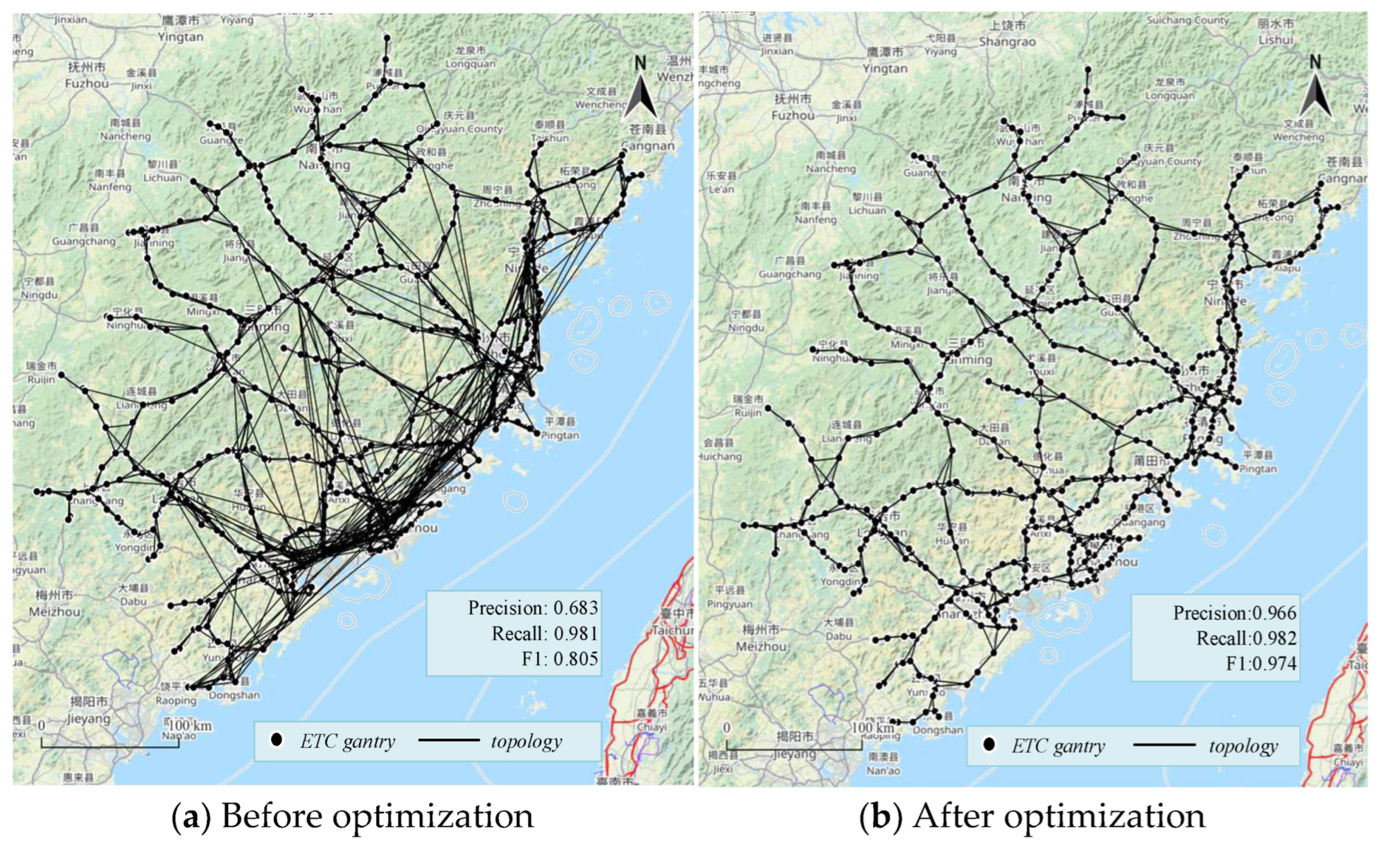
In this section, we generated a candidate topology set using a dataset of 1 million records and evaluated the optimization results using quantitative metrics and visualization techniques. As shown in Figure 7a, although the recall rate was 0.981 before optimization, the precision and F1 scores were only 0.683 and 0.805, respectively. When projected onto a map, the resulting road network displayed disorderly and irregular patterns, with numerous anomalous topologies. However, after optimization, Figure 7b shows that the anomalous topologies were effectively removed and all evaluation indicators were superior to those before optimization. Specifically, the precision reached 0.966 and the F1 value reached 0.974.
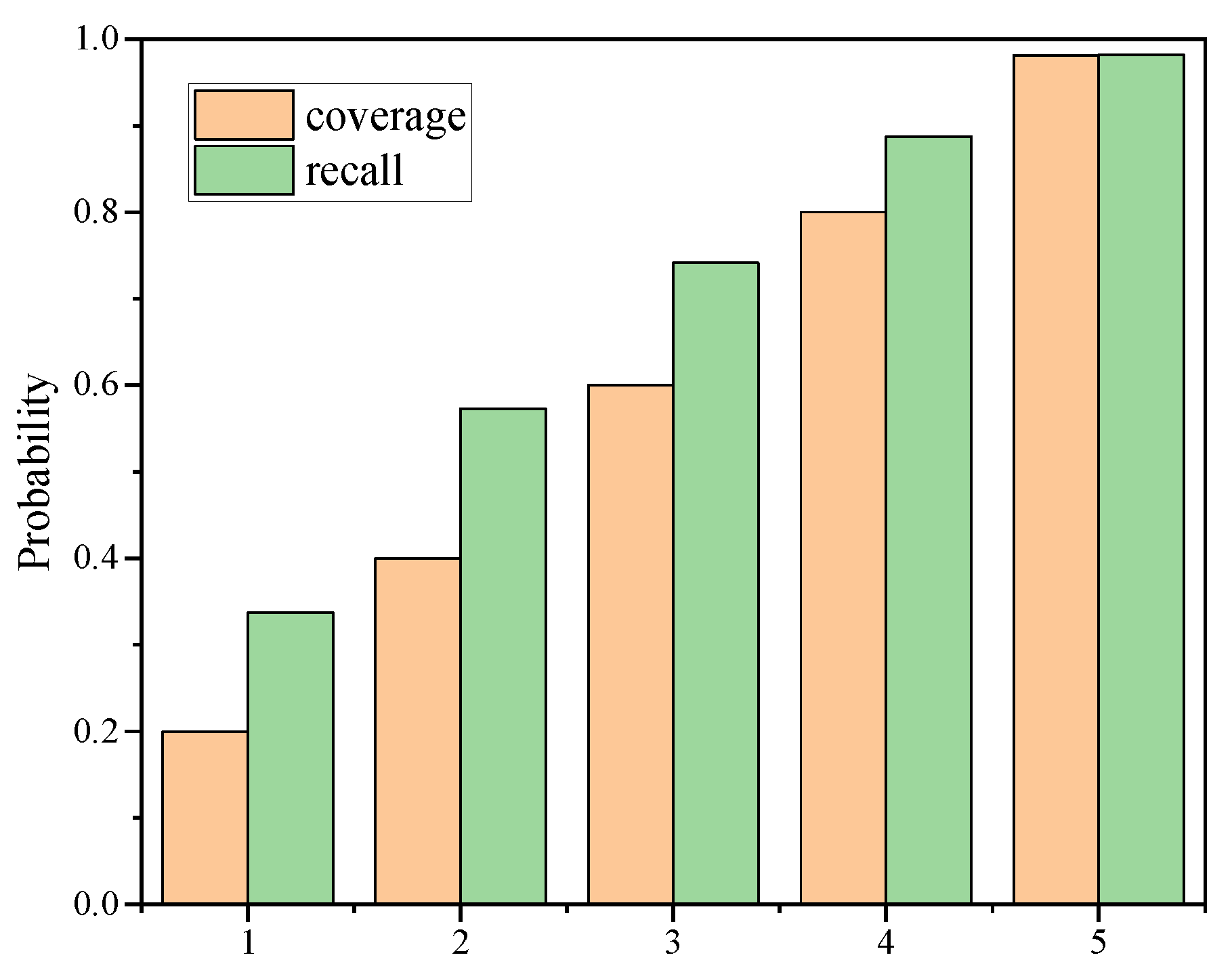
We further delved into the evaluation of topological coverage and recall rates. Figure 8 illustrates that under various levels of topological coverage, the topological recall rate is always greater than or equal to the topological coverage rate. Specifically, the corresponding recall rates were 0.34, 0.57, 0.74, 0.89, and 0.98 when the topological coverage was 0.2, 0.4, 0.6, 0.8, and 0.98, respectively. In other words, the recall was improved by 0.14, 0.17, 0.14, 0.08, and 0 for a topological coverage of 0.2, 0.4, 0.6, 0.8, and 0.98, respectively. This demonstrates that the proposed method not only identifies topologies that appear in the trajectory but also generates topologies that do not appear. Notably, when the topological coverage is low, the proposed method’s recall rate is more significant.

4.4. Efficiency

To evaluate the efficiency of the proposed method, we conducted experiments with datasets of varying sizes, which were respectively 1000, 10,000, 100,000, 1000,000 (1 M), and 10,000,000 (10 M). We repeated the experiment 10 times on each order of magnitude and calculated the mean of the running time.
As shown in Figure 9, the runtime increased slowly with the increase in data volume, showing a nearly linear relationship that tended to be smooth. Taking 1 M data volume as an example, 2950 topologies were generated, and the runtime was only 5.76 s. In other words, the average time required to generate one topology was less than 2 ms. At the same time, the running time was fitted linearly and the linear fitting equation was given. These experimental results demonstrate that our proposed method has a low time complexity, which meets the efficient demand for the automatic generation of topology in an expressway network.

5. Conclusions

A good and reasonable road network topology has important research significance and application value for traffic management and mining analysis. Therefore, in this work, we proposed an arch-bridge topology-based expressway network structure and automatic generation method for the first time. First, we propose a novel arch-bridge topology structure base on the ETC gantry system that redefines the topology of the expressway network, enabling the minimization and structuring of the complex and intertwined topology of the road network into its smallest unit. Second, by utilizing real ETC data with a user penetration rate of over 80%, our approach not only addresses the issue of insufficient data but also allows for the efficient and cost-effective extraction and improvement of the expressway road network. Third, through the deep mining and analysis of ETC data features, optimization rules are designed for loop, reverse, missing, and opposite topologies, which achieves rapid generation of the entire domain of the expressway road network topology. In addition, the expressway road network topology based on the ETC system enables the real-time monitoring of all vehicle information, making refined management of the expressway system a possibility.
We believe that automatic incremental recognition and the fast dynamic update of road network topology are worthy of further study and, on this basis, we will conduct further application research, such as abnormal trajectory detection and recognition, travel path planning, and vehicle group travel behavior mining and analysis.

Author Contributions

Conceptualization, F.Z. and D.Y.; methodology, Q.C.; software, Q.C., G.L. and W.W.; validation, D.Y., Q.C. and F.Z.; formal analysis, Q.C. and F.Z.; investigation, Q.C.; resources, F.Z.; data curation, Q.C. and D.Y.; writing—original draft preparation, Q.C. and W.W.; writing—review and editing, F.Z., Q.C., D.Y. and G.L.; visualization, Q.C., W.W. and G.L.; supervision, F.Z. and D.Y.; project administration, F.Z., X.C. and Q.C.; funding acquisition, F.Z. and X.C. All authors have read and agreed to the published version of the manuscript.

Funding

This work was funded by the National Natural Science Foundation of China (Funding number:41971340), the 2020 Fujian Province “Belt and Road” Technology Innovation Platform (Funding number:2020D002), the Provincial Candidates for the Hundred, Thousand and Ten Thousand Talent of Fujian (Funding number:GY-Z19113), the Municipal Science and Technology project (Funding number:GY-Z22006, GY-Z220230), the Open Fund project (Funding number:KF-X1902, KF-19-22001), the Patent Grant project (Funding number:GY-Z20074), and the Crosswise project (Funding number:GY-H-21021, GY-H-20077).

Institutional Review Board Statement

Not applicable.

Informed Consent Statement

Not applicable.

Data Availability Statement

Restrictions apply to the availability of these data. Data were obtained from Fujian Expressway Information Technology Co., Ltd. (Fuzhou, China) and are available from the authors with the permission of Fujian Expressway Information Technology Co., Ltd.

Conflicts of Interest

The authors declare no conflict of interest.

References

  1. Ministry of Transport of the Peoples’s Republic of China. 2021 Statistical Bulletin on the Development of the Transportation Industry; Ministry of Transport of the People’s Republic of China: Beijing, China, 2021.
  2. Qian, C.; Li, S.-y.; Wang, Y.-f. Rationalized Lanes Configuration for Expressway Gantry Plaza. J. Transp. Syst. Eng. Inf. Technol. 2021, 21, 231–237. [Google Scholar]
  3. Chiou, J.M.; Lion, H.T.; Chen, W.H. Modeling Time-Varying Variability and Reliability of Freeway Travel Time Using Functional Principal Component Analysis. IEEE Trans. Intell. Transp. Syst. 2021, 99, 1–10. [Google Scholar] [CrossRef]
  4. Chen, L.W.; Chen, D.E. Exploring Spatiotemporal Mobilities of Expressway Traffic Flows for Precise Travel Time Estimation and Prediction Based on Electronic Gantry Collection Data. Veh. Commun. 2021, 30, 100356. [Google Scholar]
  5. Luo, S.; Zou, F.; Zhang, C.; Tian, J.; Guo, F.; Liao, L. Multi-View Travel Time Prediction Based on Electronic Gantry Collection Data. Entropy 2022, 24, 1050. [Google Scholar] [CrossRef] [PubMed]
  6. Yao, E.; Wang, X.; Yang, Y.; Pan, L.; Song, Y. Traffic Flow Estimation Based on Gantry Ticket Data Considering Multitype Vehicle Impact. J. Transp. Eng. Part Syst. 2021, 147, 04020158. [Google Scholar] [CrossRef]
  7. Cai, Q.; Yi, D.; Zou, F.; Zhou, Z.; Li, N.; Guo, F. Recognition of Vehicles Entering Expressway Service Areas and Estimation of Dwell Time Using ETC Data. Entropy 2022, 24, 1208. [Google Scholar] [CrossRef]
  8. Zou, F.; Ren, Q.; Tian, J.; Guo, F.; Huang, S.; Liao, L.; Wu, J. Expressway speed prediction based on electronic toll collection data. Electronics 2022, 11, 1613. [Google Scholar] [CrossRef]
  9. Wang, H.; Zou, F.; Tian, J.; Guo, F.; Cai, Q. Analysis on Lane Capacity for Expressway Toll Station Using Toll Data. J. Adv. Transp. 2022, 2022, 9277000. [Google Scholar] [CrossRef]
  10. Tsung, C.K.; Yang, C.T.; Yang, S.W. Visualizing Potential Transportation Demand from ETC Log Analysis Using ELK Stack. IEEE Internet Things J. 2020, 7, 6623–6633. [Google Scholar] [CrossRef]
  11. Zou, F.; Guo, F.; Tian, J.; Luo, S.; Yu, X.; Gu, Q.; Liao, L. The Method of Dynamic Identify the Maximum Speed Limit of Expressway Based on Electronic Gantry Collection Data. Sci. Program. 2021, 2021, 4702669. [Google Scholar]
  12. Guo, F.; Zou, F.; Luo, S.; Chen, H.; Yu, X.; Zhang, C.; Liao, L. Positioning method of expressway ETC gantry by multi-source traffic data. IET Intell. Transp. Syst. 2022, 1–15. [Google Scholar] [CrossRef]
  13. Guo, F.; Zou, F.; Luo, S.; Liao, L.; Wu, J.; Yu, X.; Zhang, C. The Fast Detection of Abnormal ETC Data Based on an Improved DTW Algorithm. Electronics 2022, 11, 1981. [Google Scholar] [CrossRef]
  14. Zhu, L.; Wen, H. Automatic incremental identification and technology update of traffic road network data. Traffic Inf. Saf. 2009, 27, 22–24+55. [Google Scholar]
  15. Zhang, S.; Guan, G.; Zou, F.; Zhu, D. Automatic detection of additional roads by combining floating vehicle and spatial grid. Sci. Technol. Eng. 2012, 12, 5496–5501. [Google Scholar]
  16. Lian, R.; Wang, W.; Mustafa, N.; Huang, L. Road extraction methods in high-resolution remote sensing images: A comprehensive review. IEEE J. Sel. Top. Appl. Earth Obs. Remote Sens. 2020, 13, 5489–5507. [Google Scholar] [CrossRef]
  17. Kass, M.; Witkin, A.; Terzopoulos, D. Snakes: Active contour models. Int. J. Comput. Vis. 1988, 1, 321–331. [Google Scholar] [CrossRef]
  18. Péteri, R.; Ranchin, T. Multiresolution Snakes for Urban Road Extraction from Ikonos and Quickbird Images; Remote Sensing in Transition: Ghent, Belgium, 2003; pp. 141–147. [Google Scholar]
  19. Laptev, I.; Mayer, H.; Lindeberg, T.; Eckstein, W.; Steger, C. Automatic extraction of roads from aerial images based on scale space and snakes. Mach. Vis. Appl. 2000, 12, 23–31. [Google Scholar] [CrossRef]
  20. Trinder, J.C.; Wang, Y. Automatic road extraction from aerial images. Digit. Signal Process. 1998, 8, 215–224. [Google Scholar] [CrossRef]
  21. Dal Poz, A.P.; Gyftakis, S.; Agouris, P. Semiautomatic road extraction: Comparison of methodologies and experiments. In Proceedings of the 2000 ASPRS Annual Conference, Washington, DC, USA, 21–26 May 2000. [Google Scholar]
  22. Gruen, A.; Li, H. Road extraction from aerial and satellite images by dynamic programming. ISPRS J. Photogramm. Remote Sens. 1995, 50, 11–20. [Google Scholar] [CrossRef]
  23. Dal Poz, A.P.; Do Vale, G.M. Dynamic programming approach for semi-automated road extraction from medium-and high-resolution images. ISPrS Arch. 2003, 34, W8. [Google Scholar]
  24. Wegner, J.D.; Montoya-Zegarra, J.A.; Schindler, K. Road networks as collections of minimum cost paths. ISPRS J. Photogramm. Remote Sens. 2015, 108, 128–137. [Google Scholar] [CrossRef]
  25. Mokhtarzade, M.; Zoej, M.J.V. Road detection from high-resolution satellite images using artificial neural networks. Int. J. Appl. Earth Obs. Geoinf. 2007, 9, 32–40. [Google Scholar] [CrossRef]
  26. Kirthika, A.; Mookambiga, A. Automated road network extraction using artificial neural network. In Proceedings of the 2011 International Conference on Recent Trends in Information Technology (ICRTIT), Chennai, India, 3–5 June 2011; pp. 1061–1065. [Google Scholar]
  27. Mountrakis, G.; Im, J.; Ogole, C. Support vector machines in remote sensing: A review. ISPRS J. Photogramm. Remote Sens. 2011, 66, 247–259. [Google Scholar] [CrossRef]
  28. Yager, N.; Sowmya, A. Support vector machines for road extraction from remotely sensed images. In Proceedings of the International Conference on Computer Analysis of Images and Patterns, Groningen, The Netherlands, 25–27 August 2003; Springer: Berlin/Heidelberg, Germany, 2003; pp. 285–292. [Google Scholar]
  29. Mirnalinee, T.T.; Das, S.; Varghese, K. An integrated multistage framework for automatic road extraction from high resolution satellite imagery. J. Indian Soc. Remote Sens. 2011, 39, 1–25. [Google Scholar] [CrossRef]
  30. Mnih, V.; Hinton, G.E. Learning to detect roads in high-resolution aerial images. In Proceedings of the European Conference on Computer Vision, Crete, Greece, 5–11 September 2010; Springer: Berlin/Heidelberg, Germany, 2010; pp. 210–223. [Google Scholar]
  31. Saito, S.; Yamashita, T.; Aoki, Y. Multiple object extraction from aerial imagery with convolutional neural networks. Electron. Imaging 2016, 2016, 1–9. [Google Scholar] [CrossRef]
  32. Ronneberger, O.; Fischer, P.; Brox, T. U-net: Convolutional networks for biomedical image segmentation. In Proceedings of the International Conference on Medical Image Computing and Computer-Assisted Intervention, Munich, Germany, 5–9 October 2015; Springer: Cham, Switzerland, 2015; pp. 234–241. [Google Scholar]
  33. Du, G.; Cao, X.; Liang, J.; Chen, X.; Zhan, Y. Medical image segmentation based on u-net: A review. J. Imaging Sci. Technol. 2020, 64, 1–12. [Google Scholar] [CrossRef]
  34. Diakogiannis, F.I.; Waldner, F.; Caccetta, P.; Wu, C. ResUNet-a: A deep learning framework for semantic segmentation of remotely sensed data. ISPRS J. Photogramm. Remote Sens. 2020, 162, 94–114. [Google Scholar] [CrossRef]
  35. Sultonov, F.; Park, J.H.; Yun, S.; Lim, D.W.; Kang, J.M. Mixer U-Net: An Improved Automatic Road Extraction from UAV Imagery. Appl. Sci. 2022, 12, 1953. [Google Scholar] [CrossRef]
  36. Wagstaff, K.; Cardie, C.; Rogers, S.; Schrödl, S. Constrained k-means clustering with background knowledge. In Proceedings of the Eighteenth International Conference on Machine Learning, Virtual, 18–24 August 2001; Volume 1, pp. 577–584. [Google Scholar]
  37. Schroedl, S.; Wagstaff, K.; Rogers, S.; Langley, P.; Wilson, C. Mining GPS traces for map refinement. Data Min. Knowl. Discov. 2004, 9, 59–87. [Google Scholar] [CrossRef]
  38. Edelkamp, S.; Schrödl, S. Route planning and map inference with global positioning traces. In Computer Science in Perspective; Springer: Berlin/Heidelberg, Germany, 2003; pp. 128–151. [Google Scholar]
  39. Worrall, S.; Nebot, E. Automated process for generating digitised maps through GPS data compression. In Proceedings of the Australasian Conference on Robotics and Automation, Brisbane, Australia, 10–12 December 2007; ACRA: Brisbane, Australia, 2007; Volume 6. [Google Scholar]
  40. Chen, C.; Lu, C.; Huang, Q.; Yang, Q.; Gunopulos, D.; Guibas, L. City-scale map creation and updating using GPS collections. In Proceedings of the 22nd ACM SIGKDD International Conference on Knowledge Discovery and Data Mining, San Francisco, CA, USA, 13–17 August 2016; pp. 1465–1474. [Google Scholar]
  41. Sasaki, Y.; Yu, J.; Ishikawa, Y. Road segment interpolation for incomplete road data. In Proceedings of the 2019 IEEE International Conference on Big Data and Smart Computing (BigComp), Kyoto, Japan, 27 February–2 March 2017; pp. 1–8. [Google Scholar]
  42. Huang, J.; Zhang, Y.; Deng, M.; He, Z. Mining crowdsourced trajectory and geo-tagged data for spatial-semantic road map construction. Trans. GIS 2022, 26, 735–754. [Google Scholar] [CrossRef]
  43. Silverman, B.W. Density Estimation for Statistics and Data Analysis; Routledge: Oxfordshire, UK, 2018. [Google Scholar]
  44. Uduwaragoda, E.; Perera, A.S.; Dias, S.A.D. Generating lane level road data from vehicle trajectories using kernel density estimation. In Proceedings of the 16th International IEEE Conference on Intelligent Transportation Systems (ITSC 2013), The Hague, The Netherlands, 6–9 October 2013; pp. 384–391. [Google Scholar]
  45. Kuntzsch, C.; Sester, M.; Brenner, C. Generative models for road network reconstruction. Int. J. Geogr. Inf. Sci. 2016, 30, 1012–1039. [Google Scholar] [CrossRef]
  46. Neuhold, R.; Haberl, M.; Fellendorf, M.; Pucher, G.; Dolancic, M.; Rudigier, M.; Pfister, J. Generating a lane-specific transportation network based on floating-car data. In Advances in Human Aspects of Transportation; Springer: Cham, Switzerland, 2017; pp. 1025–1037. [Google Scholar]
  47. Fu, Z.; Fan, L.; Sun, Y.; Tian, Z. Density adaptive approach for generating road network from GPS trajectories. IEEE Access 2020, 8, 51388–51399. [Google Scholar] [CrossRef]
  48. Fathi, A.; Krumm, J. Detecting road intersections from GPS traces. In Proceedings of the International Conference on Geographic Information Science, Zurich, Switzerland, 14–17 September 2010; Springer: Berlin/Heidelberg, Germany, 2010; pp. 56–69. [Google Scholar]
  49. Karagiorgou, S.; Pfoser, D. On vehicle tracking data-based road network generation. In Proceedings of the 20th International Conference on Advances in Geographic Information Systems, Redondo Beach, CA, USA, 6–9 November 2012; pp. 89–98. [Google Scholar]
  50. Xingzhe, X.; Liao, W.; Aghajan, H.; Veelaert, P.; Philips, W. Detecting road intersections from GPS traces using longest common subsequence algorithm. ISPRS Int. J. Geo Inf. 2016, 6, 1. [Google Scholar]
  51. Xie, X.; Philips, W. Road intersection detection through finding common sub-tracks between pairwise GNSS traces. ISPRS Int. J. Geo Inf. 2017, 6, 311. [Google Scholar] [CrossRef]
  52. Wu, J.; Zhu, Y.; Ku, T.; Wang, L. Detecting Road Intersections from Coarse-gained GPS Traces Based on Clustering. J. Comput. 2013, 8, 2959–2965. [Google Scholar] [CrossRef]
  53. Huang, Y.; Xiao, Z.; Yu, X.; Wang, D.; Havyarimana, V.; Bai, J. Road network construction with complex intersections based on sparsely sampled private car trajectory data. ACM Trans. Knowl. Discov. Data 2019, 13, 1–28. [Google Scholar] [CrossRef]
  54. Deng, M.; Huang, J.; Zhang, Y.; Liu, H.; Tang, L.; Tang, J.; Yang, X. Generating urban road intersection models from low-frequency GPS trajectory data. Int. J. Geogr. Inf. Sci. 2018, 32, 2337–2361. [Google Scholar] [CrossRef]
  55. Pu, M.; Mao, J.; Du, Y.; Shen, Y.; Jin, C. Road intersection detection based on direction ratio statistics analysis. In Proceedings of the 2019 20th IEEE International Conference on Mobile Data Management (MDM), Hong Kong, China, 10–13 June 2019; pp. 288–297. [Google Scholar]
  56. Zhao, L.; Mao, J.; Pu, M.; Liu, G.; Jin, C.; Qian, W.; Zhou, A.; Wen, X.; Hu, R.; Chai, H. Automatic calibration of road intersection topology using trajectories. In Proceedings of the 2020 IEEE 36th International Conference on Data Engineering (ICDE), Dallas, TX, USA, 20–24 April 2020; pp. 1633–1644. [Google Scholar]
  57. Qing, R.; Liu, Y.; Zhao, Y.; Liao, Z.; Liu, Y. Using Feature Interaction among GPS Data for Road Intersection Detection. In Proceedings of the 2nd International Workshop on Human-centric Multimedia Analysis, Virtual, 20–24 October 2021; pp. 31–37. [Google Scholar]
  58. Liu, Y.; Qing, R.; Zhao, Y.; Liao, Z. Road Intersection Recognition via Combining Classification Model and Clustering Algorithm Based on GPS Data. ISPRS Int. J. Geo Inf. 2022, 11, 487. [Google Scholar] [CrossRef]
  59. Ministry of Transport of the Peoples’s Republic of China. ETC Gantry System Technical Requirements for Expressways; Ministry of Transport of the People’s Republic of China: Beijing, China, 2019.
  60. Dijkstra, E.W. A note on two problems in connexion with graphs. Numer. Math. 1959, 1, 269–271. [Google Scholar] [CrossRef]
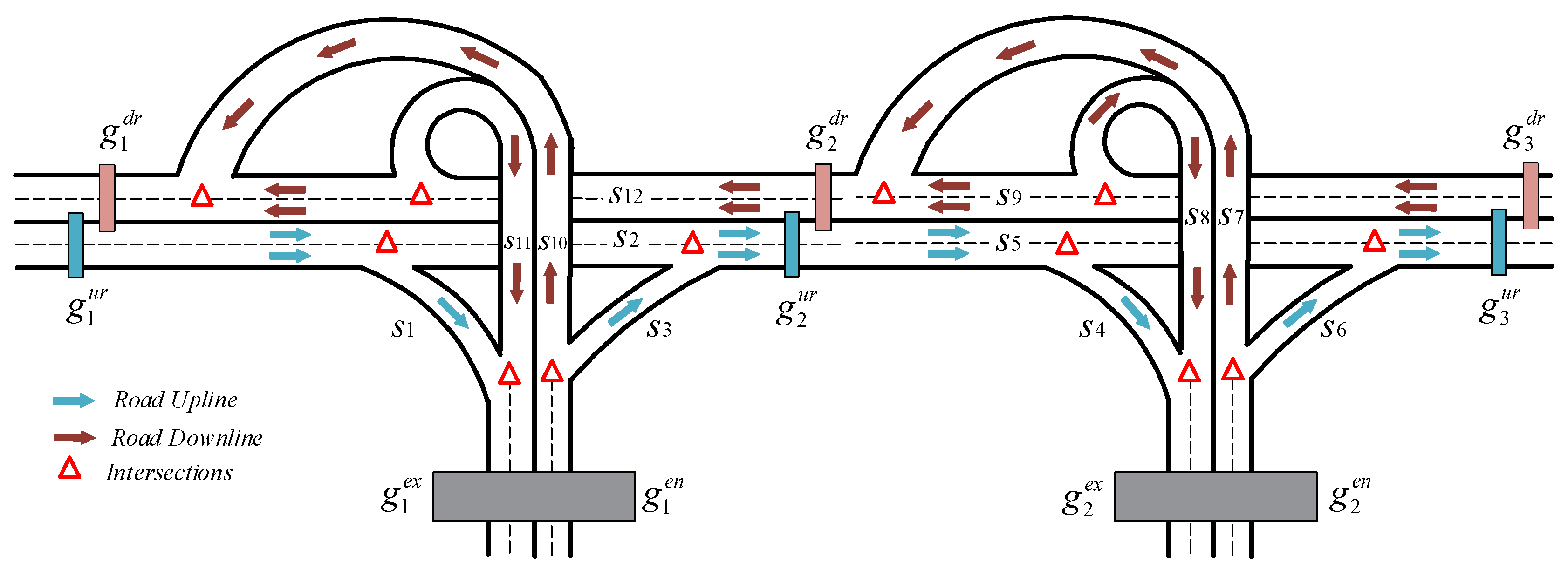
Figure 1. A simple road network.
Applsci 13 05031 g001
Figure 2. Arch-bridge topology.
Applsci 13 05031 g002
Figure 3. An example of road trajectory.
Applsci 13 05031 g003
Figure 4. Schematic diagram of the abnormal topology. (a) loop topology; (b) missing topology; (c) opposite topology; (d) reverse topology.
Applsci 13 05031 g004
Figure 5. Visualization of ETC gantry deployment in a province.
Applsci 13 05031 g005
Figure 6. The relationship between data size and topology coverage.
Applsci 13 05031 g006
Figure 7. Visualization of road network topology.
Applsci 13 05031 g007
Figure 8. The relationship between recall and coverage.
Applsci 13 05031 g008
Figure 9. Efficiency assessment at different data volumes.
Applsci 13 05031 g009
Table 1. Description of Partial Attributes in ETC Transaction Data.
IndexField NameField PropertiesExample
1GantryIDgantry id number349E61
2GantryTypegantry type2
3TradeTimegantry trade time01/06/2021 08:00:00
4OBUidvehicle identification1775853281
5PassIDitinerary number0123…….741
Disclaimer/Publisher’s Note: The statements, opinions and data contained in all publications are solely those of the individual author(s) and contributor(s) and not of MDPI and/or the editor(s). MDPI and/or the editor(s) disclaim responsibility for any injury to people or property resulting from any ideas, methods, instructions or products referred to in the content.