Abstract
The direct-ink-writing (DIW) has been widely used to print various functional devices using different self-leveling inks. Due to the complicated rheological behavior and multiple processing parameters, how to rapidly determine the crucial parameter for high-precision printing is still challenging. Here we adapt a widely used commercial silver paste and identify the critical parameter for dominating the flatness through observation of the microstructure evolution for the line-to-layer forming process. An analytical model for flatness with printing parameters was established. Using the proposed model, the printing process parameters for achieving high flatness can be directly determined, avoiding the high cost of extensive experimental exploration.
1. Introduction
Direct-ink-writing (DIW) is an additive manufacturing technology that is widely employed in diverse fields, ranging from sensors [1,2,3,4,5], soft robotics [6,7,8], wearable electronics [9,10], tissue engineering [11,12,13], stretchable electronics [14,15,16], to microfluidics [17,18]. This technology offers the possibility of rapid printing of complex 3D structures using various inks, including conductive pastes [14,16], elastomers [8,19,20,21], and hydrogels [22,23,24,25,26]. In the realm of rheological materials, inks that possess self-leveling properties, such as conductive inks, hydrogels, and PDMS, are highly printable and versatile, which demonstrate immense potential for a wide range of electronic applications [15,16].
Compared to traditional manufacturing methods, DIW is constrained by the shaping process from lines to layer. Additionally, the printing process involves a complex array of parameters, making it difficult to rapidly optimize these parameters to achieve controlled layer thickness, high flatness, and precision printing. Regarding this particular issue, Yuk and Zhao [27] built a phase diagram of printing parameters, which can guide the printing of viscoelastic ink fibers of different shapes, and break through the limitation of line resolution to print fibers finer than the diameter of the nozzle. Their main contribution inspired this paper on how to construct a geometric model describing the layer surface and control key parameters to achieve high-precision printing of ink layers.
At present, there are few studies on the flatness of the DIW printing surface. Felden et al. [28] used different nozzle diameters to print ceramic materials and found that large nozzle diameters lead to a lower dimensional accuracy. Buj-Corral et al. [29] studied the effect of printing parameters on the dimensional error and the surface roughness of the ceramic part. In our previous study [3], we provided an optimized set of process parameters for achieving high surface smoothness in self-leveling ink printing based on the observed effects of changes in needle inner diameter and line spacing. However, experimental observations and measurements typically only yield descriptive and phenomenological laws, whose applicability is usually limited to the same type of material.
In addition, there are many studies on optimizing surface flatness for fused deposition modeling (FDM) [30,31,32]. Although the line-to-plane forming process of DIW is similar to FDM, the surface morphology of DIW is significantly different from that of FDM, especially the self-leveling inks is used for DIW. For the FDM materials, the section of the printed line almost keeps a circle shape after welding. The roughness of the FDM printed surface is mainly determined by the rising height (related to line width) [30]. For the DIW-printed self-leveling inks studied in this work, the extrusion-formed surface before curing tends to reach high flatness but finally forms a rippling morphology induced by the evaporation speed gradient. The different mechanisms of material forming behaviors between the FDM and DIW lead to different mathematical models. Therefore, the generality of the proposed model is not expected to be compatible with the FDM surface flatness optimization.
To investigate the influence mechanism of crucial parameters on the flatness of printing layers, we carefully observed the microstructure evolution process from line to plane of the self-leveling printing ink and identified the critical parameters that effect the flatness. A quantitative parameter for flatness characterization was proposedly based on the microstructure geometric features. On this basis, a mathematical model for flatness with printing parameters was established. Using the proposed model, the printing process parameters for achieving high flatness can be directly determined, avoiding the high cost of extensive experimental exploration.
2. Materials and Methods
Printing of ink surface: A three-axis robot (SHOT, mini 200SX, MUSASHI) was used to control the nozzle to move in an S-shaped path, with the path programmed using the software (MUCADV). A dispensing machine (ML-5000XII, MUSASHI) was used to control the extrusion of ink from the nozzle. During the printing process, only nozzles with an inner diameter of 410 μm (RUIWING) were used, and the nozzle height hn was kept greater than or equal to the nozzle inner diameter dn to avoid the nozzle scraping the ink. Glass slides were used as substrates. After printing, the ink was cured for 24 h in the atmosphere. The air pressure of the dispensing machine could not be too low to ensure continuous extrusion of ink from the nozzle in a cylindrical shape (as shown in Figure 1). It was found through experimentation that the silver paste could be extruded in a cylindrical shape from the nozzle with an inner diameter of 410 μm when the air pressure of the dispensing machine was 400 KPa.
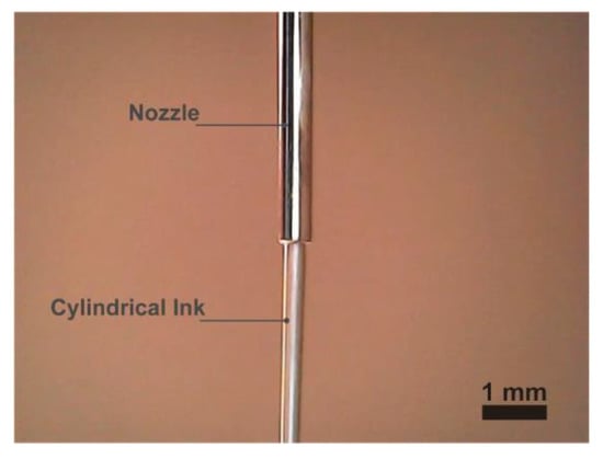
Figure 1.
Schematic diagram of cylindrical ink extrusion from a nozzle.
Measurement of ink surface flatness: A white light interferometer (FMD-D) was used to obtain surface information of the ink layers. The surface profile data of the ink surface were obtained and processed using software (gwyddion).
Rheological properties of the silver paste: Figure 2a shows that the silver paste used has a low zero-shear rate viscosity and shear-thinning characteristics. Figure 2b,c show that the silver paste has no significant yield stress and tends to remain in a liquid state. When measuring viscosity and shear stress, the parameters are set as follows: Mod is CR, distribution is line, type is stepwise, Duration is 120 s and Temperature is 25°. When measuring storage modulus G′ and loss modulus G″, the parameters are set as follows: Mode is CS, Shear stress τ0 is 1.00 Pa, Distribution is Log, Freq/Decade is 6 based on ω and Temperature is 25°. For the measurement of rheological properties of carbon paste (CH-8, JELCON), please see Supplementary Materials.

Figure 2.
(a) Apparent steady-state viscosity η as a function of shear strain rate. (b) Shear stress as a function of shear strain rate. (c) Storage modulus G′ and loss modulus G″ as a function of angular frequency ω.
Measurement of the contact angle: The contact angle between the ink and the substrate is a parameter related to the surface tension. The width of the single printed ink line is affected by the contact angle. When printing the ink layer, the contact angle affects the slope of the border between stacked ink lines. The measuring instrument (XG-CAM, XYCXIE) is used to measure the contact angle at different contact diameters. Figure 3 shows the measured contact angle data. For the detailed process of measuring contact angle, please see Supplementary Materials.

Figure 3.
Contact angle θ as a function of contact diameter dc. The dotted line is the average value of the measured contact angles.
3. Results
3.1. Analytical Modelling
Figure 4 illustrates the typical steps and parameters of printing a layer using self-leveling ink through DIW technology. During the printing process, the nozzle moves laterally at a speed of vn at a height hn from the substrate, while the ink is extruded from the nozzle by air pressure to print an ink line with a width l on the substrate. Surface tension causes a contact angle θ to form between the ink line and the substrate. Multiple ink lines with a spacing of ls (ls < l) can be printed side by side to create an ink layer. The crucial parameter controlling the layer thickness is the line width l, which depends mainly on process parameters such as the nozzle inner diameter dn, nozzle moving speed vn, and ink extrusion speed ve. Previous work has shown that printing thinner layers is critical for improving the interface strength of multi-layer sensor composite structures [3]. Among the related printing parameters, the line spacing ls is the crucial parameter controlling the flatness of the ink layers. When the line spacing is too small, the overlap between adjacent ink lines increases the overall layer thickness (higher than the height of a single line), making it difficult to obtain the desired thin layer. Increasing the line spacing leads to the formation of ripples on the surface of the layer during the process of forming lines into a surface due to surface tension, which affects the flatness of the layer. In addition, if the spacing between adjacent ink lines exceeds the maximum gap that can be covered by self-leveling fusion, it is unable to print a complete flat surface. To achieve controllable printing of layer thickness and surface ripple, a large number of expensive process optimization experiments are necessary, and usually only empirical rules can be summarized, making it difficult to obtain a universal theoretical model.

Figure 4.
Schematic diagram of the process for printing an ink layer using DIW technology. During the printing process, the nozzle moves laterally at a velocity of vn at a height hn from the substrate, while the ink is extruded from the nozzle to print multiple ink lines in parallel with a spacing of ls. These ink lines merge through self-leveling, forming a flat surface. When printing a single ink line, a line with a width of l and a contact angle of θ is formed due to the self-leveling properties.
To address the aforementioned issues, we first observed and summarized the microstructural evolution of the ink during the forming process of lines-to-layer using DIW printing, and then identified the key governing parameters. Subsequently, a processing model was established to control the surface morphology with high precision. Based on this model, high-precision printing of layers with controllable thickness and high flatness can be achieved. The work presented in this paper offers a low-cost and rational solution for achieving high-precision, controllable direct writing printing.
A widely used silver ink (CD-03, Conduction) is used to print multiple ink lines, with the spacing between lines controlled to be less than the line width, so that multiple lines can merge to form a plane. However, the uncured layer with planar surface (Figure 5a–c) becomes rippled after curing (Figure 5d–f). Figure 5a shows the optical image of the ink surface before solidification, where the color at the intersection of the ink lines is darker than at other locations. Figure 5b shows the white light interference image of the ink surface before curing, indicating high flatness. Figure 5c shows the cross-sectional profile corresponding to Figure 5b. Figure 5d,e show the optical and white light interference images of the ink surface after curing, respectively, revealing that the wave-like ripples on the layer surface are formed. Figure 5f shows the cross-sectional profile corresponding to Figure 5e. It is indicated that this is caused by differences in density at the intersection of the ink lines compared to other locations, which will be discussed later. Figure 6a shows the general process of lines to layer. The extruded ink lines merge to form a layer with relatively high flatness due to the self-leveling of the ink. The contact angle affects the slope of the border between stacked ink lines (Figure 6a), which may affect the flatness of the ink layer before leveling to a plane. However, the printed ink layer only keeps ripple morphology as a processing intermediated state and will tend to flat-plane induced by the leveling. The final flatness after curing is mainly dominated by the evaporation gradient from the interfaces among the adjacent lines into the inner of the lines. In order to reduce the ripples to improve the flatness, we established a model to quantify the relationship for the ripple height with the crucial parameter of line spacing. Using this model, the optimization processing parameters for high flatness printing can be directly determined. In order to simplify the model, some assumptions are put forward according to the observation based on tests: (i) the ink layer is fully leveled before curing; (ii) the lateral dimension of the ink layer will not change after curing; (iii) the angle α between the circular arc and the vertical line passing through the highest point of the stripe is a constant value; (iv) the solid loading of the ink is not taken into account.
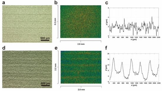
Figure 5.
(a) Optical image of the layer surface before curing. (b) White light interference image of the layer surface before curing. (c) the corresponding cross-sectional profiles of (b). (d) Optical image of the layer surface after curing. (e) White light interference image of the layer surface after curing. (f) the corresponding cross-sectional profiles of (e).

Figure 6.
(a) Curing process of layer surface after printing. After printing the layer surface, the ink will flatten into a relatively smooth surface. Upon curing, the layer surface will exhibit aligned ripples. (b) Schematic diagram of the layer surface geometry model when ls is less than ls0. (c) Schematic diagram of the layer surface geometry model when ls is greater than ls0.
Experimental results have shown that the geometric shape of the stripes formed after ink curing varies slightly with the spacing ls between ink lines on the printing plane. As shown in Figure 6b, when ls is less than or equal to a certain value ls0, the vertical cross-sectional profile of the ink-cured surface can be approximated by multiple circular arcs. Assuming that the angle α between the circular arc and the vertical line passing through the highest point of the stripe is a constant value, we can establish a model to describe the profile of the ink-cured surface:
where (x, y) are the cartesian coordinate points, representing the cross-sectional profile of the ink layer. The symbol k represents the number for kth strip; rc = ls/2cosα is the radius of the arc. As shown in Figure 6c, when the distance between ink lines on the printing surface ls is greater than a certain value ls0, the height of the striped protrusions no longer changes, and the radius of the arc rc also remains unchanged. There is a relatively flat contour between the striped protrusions. Therefore, we can represent the contour model as:
where, rc0 = ls0/2cosα is the constant radius of the arc when the line spacing ls is greater than ls0. For detailed derivation of the geometric model, please see Supplementary Materials.
If the maximum height difference ΔH of the cross-sectional profile is used to describe the flatness of the ink surface, theoretical calculations can be performed to obtain:
3.2. Model Verification
For the silver paste, α of 81° and a nominal line spacing ls0 of 409 μm are determined by testing. Figure 7 shows the white light interference images of the ink surface obtained at different line spacings, as well as a comparison of the experimental and theoretical cross-sectional profiles. Figure 8 shows a comparison between the maximum height difference of the ink surface obtained experimentally and that predicted by the theoretical model for different line spacings. The average value of height measured for each peak of the ripple are calculated as the ΔH. It is shown that the experimental results agree well with the theoretical model. Furthermore, it is suggested from the model that the smaller the line spacing ls, the smaller the height difference ΔH. However, in practical experiments, there is a lower limit for the line spacing lsm, below which the flatness of the ink surface cannot be further improved. In this case, the surface roughness is dominated by the inclusion particle sizes, which are greater than the height of ripples. Moreover, the critical line spacing lsm for the silver paste is experimentally calibrated around 204 μm.

Figure 7.
White light interference images and corresponding cross-sectional profiles and maximum height differences ΔH under different ls. The solid line is the cross-sectional profile measured by the experiment, and the dashed line is the cross-sectional profile predicted by the model.

Figure 8.
Relationship between the maximum height difference ΔH of the layer surface and the line spacing ls. The solid line represents the theoretical prediction, and the solid circles represent the experimental values.
The layer thickness can be adjusted by controlling the extrusion volume per unit length. As shown in Figure 6a, based on the volume conservation for the printing ink, the layer thickness is determined by:
where Sp is the cross-sectional area of a single printed ink line. As shown in Figure 4, if Sp is calculated using the ink line width l, then Sp = bl2/4, where b is a fixed value determined by the contact angle θ and is given by b = θ/sin2θ − cosθ/sinθ. The symbol hl is the overall thickness of the cured ink surface, and a is the solid content. If the layer thickness is estimated based on the width of a single ink line, then:
For detailed derivation of the equation for calculating layer thickness, please see Supplementary Materials.
4. Discussion
One of the novelties revealed in this work is the transition status with a highly flat surface before the curing. How the ripples emerge from a flat uncured layer is curious. For the silver paste with high viscosity, the boundary of the extruded line cannot be completely eliminated after the adjacent lines merge. Therefore, in the optical image in Figure 5a, there are visually dark stripes even if the layer surface is quite flat (Figure 5b,c). After curing, the ripples form at the periodic dark-stripe locations, affecting the flatness. The residual boundary between the overlapped lines accelerates the curing process. The adjacent ink is driven by surface tension to gather at the boundary location. Consequently, the gathered ink forms the ripple after curing is completed. This phenomenon may be similar to the coffee ring effect. The ink at the boundary evaporates and solidifies faster, so that the ink at other positions flows to this place, resulting in more solidified ink at the boundary than other positions. A carbon paste similar to the silver paste is used to print the ink layer (see Figure S5 in the Supplementary Materials). Ripples were also observed on the surface of the carbon paste layer. The in-depth mechanism for this phenomenon will be explored in the future studies.
When the spacing is small (204–307 μm), as shown in Figure 7, the proposed theoretical model predicts ΔH is slightly higher than the experimental value. It is concluded that the α becomes slightly larger than the constant value for small ls (204–307 μm). α slightly decreases with ls and tends to a stable value until ls > ls0. It is believed that α can be generally treated as material constant. The slight increment of α for ls around 204–307 μm may be attributed to the enhanced interaction between excessively overlapped lines.
5. Conclusions
In this study, we systematically analyzed the microscope morphology evolution during the forming process from lines to layer, in order to precisely control the thickness and flatness for DIW printing. We identified the key parameters and developed a mechanical model for optimizing the processing parameters of self-leveling. The proposed model provides new insights into the analytical-model-based processing parameter optimization for extrusion-type DIW 3D printing technology.
Supplementary Materials
The following supporting information can be downloaded at: https://www.mdpi.com/article/10.3390/app13084950/s1, Figure S1: Rheological characteristics of the carbon paste; Figure S2. (a) Image of the ink droplet adhered to the substrate taken for the calculation of the contact angle. (b) schematic diagram for calculating the contact angle; Figure S3. (a) Schematic diagram of the kth arc profile when ls ≤ ls0. (b) Schematic diagram of the surface profile of the kth cured ink line when ls > ls0; Figure S4. (a) Schematic diagram of the cross-section of a single ink line. (b) Schematic diagram of the cross-section of the ink line after leveling. (c) Schematic diagram of the cross-section of ink lines after curing; Figure S5: Optical images at lower magnification of ink layers printed with silver paste and carbon paste (CH-8, JELCON).
Author Contributions
Conceptualization, P.Y.; methodology, P.Y.; validation, Y.T. and P.Y.; formal analysis, M.L.; investigation, M.L.; resources, P.Y.; writing—original draft preparation, M.L.; writing—review and editing, P.Y. and Y.T.; visualization, M.L.; supervision, P.Y.; project administration, P.Y. All authors have read and agreed to the published version of the manuscript.
Funding
We gratefully acknowledge the financial support from the State Key Laboratory of Mechanics and Control of Mechanical Structures (Nanjing University of Aeronautics and Astronautics, Grant No. MCMS-E-0422G04), the Open Fund of Key Laboratory for Intelligent Nano Materials and Devices of the Ministry of Education NJ2020003 (INMD-2021M05), the Postdoctoral Science Foundation of China (Grant No. 2018M630513), the 111 project (Grant No. B18027).
Data Availability Statement
The data that support the findings of this study are available from the corresponding author upon reasonable request.
Conflicts of Interest
The authors declare no conflict of interest.
References
- Wang, Z.; Guan, X.; Huang, H.; Wang, H.; Lin, W.; Peng, Z. Full 3D Printing of Stretchable Piezoresistive Sensor with Hierarchical Porosity and Multimodulus Architecture. Adv. Funct. Mater. 2019, 29, 1807569. [Google Scholar] [CrossRef]
- Guo, Z.; Xu, J.; Chen, Y.; Guo, Z.; Yu, P.; Liu, Y.; Zhao, J. High-sensitive and stretchable resistive strain gauges: Parametric design and DIW fabrication. Compos. Struct. 2019, 223, 110955. [Google Scholar] [CrossRef]
- Guo, Z.; Yu, P.; Liu, Y.; Zhao, J. High-precision resistance strain sensors of multilayer composite structure via direct ink writing: Optimized layer flatness and interfacial strength. Compos. Sci. Technol. 2021, 201, 108530. [Google Scholar] [CrossRef]
- Guo, Z.; Yu, P.; Liu, Y.; Zhao, J. Pre-fatigue enhancing both long-term stability and sensitivity of direct-ink-writing printed sensors. Int. J. Fatigue 2023, 166, 107237. [Google Scholar] [CrossRef]
- Yu, P.; Qi, L.; Guo, Z.; Lin, S.; Liu, Y.; Zhao, J. Arbitrary-shape-adaptable strain sensor array with optimized circuit layout via direct-ink-writing: Scalable design and hierarchical printing. Mater. Des. 2022, 214, 110388. [Google Scholar] [CrossRef]
- Zhang, Y.-F.; Zhang, N.; Hingorani, H.; Ding, N.; Wang, D.; Yuan, C.; Zhang, B.; Gu, G.; Ge, Q. Fast-Response, Stiffness-Tunable Soft Actuator by Hybrid Multimaterial 3D Printing. Adv. Funct. Mater. 2019, 29, 1806698. [Google Scholar] [CrossRef]
- Rus, D.; Tolley, M.T. Design, fabrication and control of soft robots. Nature 2015, 521, 467–475. [Google Scholar] [CrossRef]
- Wehner, M.; Truby, R.L.; Fitzgerald, D.J.; Mosadegh, B.; Whitesides, G.M.; Lewis, J.A.; Wood, R.J. An integrated design and fabrication strategy for entirely soft, autonomous robots. Nature 2016, 536, 451–455. [Google Scholar] [CrossRef]
- Chen, K.; Zhang, L.; Kuang, X.; Li, V.; Lei, M.; Kang, G.; Wang, Z.L.; Qi, H.J. Dynamic Photomask-Assisted Direct Ink Writing Multimaterial for Multilevel Triboelectric Nanogenerator. Adv. Funct. Mater. 2019, 29, 1903568. [Google Scholar] [CrossRef]
- Chen, S.; Huang, T.; Zuo, H.; Qian, S.; Guo, Y.; Sun, L.; Lei, D.; Wu, Q.; Zhu, B.; He, C.; et al. A Single Integrated 3D-Printing Process Customizes Elastic and Sustainable Triboelectric Nanogenerators for Wearable Electronics. Adv. Funct. Mater. 2018, 28, 1805108. [Google Scholar] [CrossRef]
- Huan, S.; Mattos, B.D.; Ajdary, R.; Xiang, W.; Bai, L.; Rojas, O.J. Two-Phase Emulgels for Direct Ink Writing of Skin-Bearing Architectures. Adv. Funct. Mater. 2019, 29, 1902990. [Google Scholar] [CrossRef]
- Kang, H.-W.; Lee, S.J.; Ko, I.K.; Kengla, C.; Yoo, J.J.; Atala, A. A 3D bioprinting system to produce human-scale tissue constructs with structural integrity. Nat. Biotechnol. 2016, 34, 312–319. [Google Scholar] [CrossRef] [PubMed]
- Lind, J.U.; Busbee, T.A.; Valentine, A.D.; Pasqualini, F.S.; Yuan, H.; Yadid, M.; Park, S.-J.; Kotikian, A.; Nesmith, A.P.; Campbell, P.H.; et al. Instrumented cardiac microphysiological devices via multimaterial three-dimensional printing. Nat. Mater. 2017, 16, 303–308. [Google Scholar] [CrossRef]
- Muth, J.T.; Vogt, D.M.; Truby, R.L.; Mengüç, Y.; Kolesky, D.B.; Wood, R.J.; Lewis, J.A. Embedded 3D Printing of Strain Sensors within Highly Stretchable Elastomers. Adv. Mater. 2014, 26, 6307–6312. [Google Scholar] [CrossRef]
- Tian, K.; Bae, J.; Bakarich, S.E.; Yang, C.; Gately, R.D.; Spinks, G.M.; in het Panhuis, M.; Suo, Z.; Vlassak, J.J. 3D Printing of Transparent and Conductive Heterogeneous Hydrogel–Elastomer Systems. Adv. Mater. 2017, 29, 1604827. [Google Scholar] [CrossRef]
- Ahn, B.Y.; Duoss, E.B.; Motala, M.J.; Guo, X.; Park, S.-I.; Xiong, Y.; Yoon, J.; Nuzzo, R.G.; Rogers, J.A.; Lewis, J.A. Omnidirectional Printing of Flexible, Stretchable, and Spanning Silver Microelectrodes. Science 2009, 323, 1590–1593. [Google Scholar] [CrossRef] [PubMed]
- Wu, W.; DeConinck, A.; Lewis, J.A. Omnidirectional Printing of 3D Microvascular Networks. Adv. Mater. 2011, 23, H178–H183. [Google Scholar] [CrossRef]
- Therriault, D.; White, S.R.; Lewis, J.A. Chaotic mixing in three-dimensional microvascular networks fabricated by direct-write assembly. Nat. Mater. 2003, 2, 265–271. [Google Scholar] [CrossRef]
- Duoss, E.B.; Weisgraber, T.H.; Hearon, K.; Zhu, C.; Small IV, W.; Metz, T.R.; Vericella, J.J.; Barth, H.D.; Kuntz, J.D.; Maxwell, R.S.; et al. Three-Dimensional Printing of Elastomeric, Cellular Architectures with Negative Stiffness. Adv. Funct. Mater. 2014, 24, 4905–4913. [Google Scholar] [CrossRef]
- Zhou, L.-y.; Fu, J.-z.; Gao, Q.; Zhao, P.; He, Y. All-Printed Flexible and Stretchable Electronics with Pressing or Freezing Activatable Liquid-Metal–Silicone Inks. Adv. Funct. Mater. 2020, 30, 1906683. [Google Scholar] [CrossRef]
- Jakus, A.E.; Rutz, A.L.; Jordan, S.W.; Kannan, A.; Mitchell, S.M.; Yun, C.; Koube, K.D.; Yoo, S.C.; Whiteley, H.E.; Richter, C.-P.; et al. Hyperelastic “bone”: A highly versatile, growth factor–free, osteoregenerative, scalable, and surgically friendly biomaterial. Sci. Transl. Med. 2016, 8, 358ra127. [Google Scholar] [CrossRef] [PubMed]
- Sun, Z.; Lu, Y.; Zhao, Q.; Wu, J. A new stereolithographic 3D printing strategy for hydrogels with a large mechanical tunability and self-weldability. Addit. Manuf. 2022, 50, 102563. [Google Scholar] [CrossRef]
- McCracken, J.M.; Rauzan, B.M.; Kjellman, J.C.E.; Su, H.; Rogers, S.A.; Nuzzo, R.G. Ionic Hydrogels with Biomimetic 4D-Printed Mechanical Gradients: Models for Soft-Bodied Aquatic Organisms. Adv. Funct. Mater. 2019, 29, 1806723. [Google Scholar] [CrossRef]
- Hong, S.; Sycks, D.; Chan, H.F.; Lin, S.; Lopez, G.P.; Guilak, F.; Leong, K.W.; Zhao, X. 3D Printing of Highly Stretchable and Tough Hydrogels into Complex, Cellularized Structures. Adv. Mater. 2015, 27, 4035–4040. [Google Scholar] [CrossRef] [PubMed]
- Kolesky, D.B.; Truby, R.L.; Gladman, A.S.; Busbee, T.A.; Homan, K.A.; Lewis, J.A. 3D Bioprinting of Vascularized, Heterogeneous Cell-Laden Tissue Constructs. Adv. Mater. 2014, 26, 3124–3130. [Google Scholar] [CrossRef] [PubMed]
- Liu, X.; Yuk, H.; Lin, S.; Parada, G.A.; Tang, T.-C.; Tham, E.; de la Fuente-Nunez, C.; Lu, T.K.; Zhao, X. 3D Printing of Living Responsive Materials and Devices. Adv. Mater. 2018, 30, 1704821. [Google Scholar] [CrossRef]
- Yuk, H.; Zhao, X. A New 3D Printing Strategy by Harnessing Deformation, Instability, and Fracture of Viscoelastic Inks. Adv. Mater. 2018, 30, 1704028. [Google Scholar] [CrossRef]
- Feilden, E.; Blanca, E.G.-T.; Giuliani, F.; Saiz, E.; Vandeperre, L. Robocasting of structural ceramic parts with hydrogel inks. J. Eur. Ceram. Soc. 2016, 36, 2525–2533. [Google Scholar] [CrossRef]
- Buj-Corral, I.; Domínguez-Fernández, A.; Gómez-Gejo, A. Effect of Printing Parameters on Dimensional Error and Surface Roughness Obtained in Direct Ink Writing (DIW) Processes. Materials 2020, 13, 2157. [Google Scholar] [CrossRef]
- Taufik, M.; Jain, P.K. A Study of Build Edge Profile for Prediction of Surface Roughness in Fused Deposition Modeling. J. Manuf. Sci. Eng. 2016, 138, 061002. [Google Scholar] [CrossRef]
- Rahman, H.; John, T.D.; Sivadasan, M.; Singh, N.K. Investigation on the Scale Factor applicable to ABS based FDM Additive Manufacturing. Mater. Today Proc. 2018, 5, 1640–1648. [Google Scholar] [CrossRef]
- Boschetto, A.; Bottini, L. Design for manufacturing of surfaces to improve accuracy in Fused Deposition Modeling. Robot. Cim-Int. Manuf. 2016, 37, 103–114. [Google Scholar] [CrossRef]


Disclaimer/Publisher’s Note: The statements, opinions and data contained in all publications are solely those of the individual author(s) and contributor(s) and not of MDPI and/or the editor(s). MDPI and/or the editor(s) disclaim responsibility for any injury to people or property resulting from any ideas, methods, instructions or products referred to in the content. |
© 2023 by the authors. Licensee MDPI, Basel, Switzerland. This article is an open access article distributed under the terms and conditions of the Creative Commons Attribution (CC BY) license (https://creativecommons.org/licenses/by/4.0/).