Abstract
The optimization of the pile driver frame is very important to the overall performance of the pile driver. This paper examines the large body structure of a model of a hydraulic static pile driver as the research object. ANSYS APDL finite element software is used to perform static analysis and sensitivity analysis on the large body structure of the pile driver. On the premise of meeting the design requirements, according to the most dangerous working conditions of the pile driver, the size optimization of the frame structure of the pile driver is carried out based on sensitivity analysis. The mathematical model is established with the plate thickness as the design variable, the strength and stiffness of the body structure as the constraints, and the minimum mass of the body structure as the objective function. The optimization results show that the optimization design model based on sensitivity analysis not only meets the strength and stiffness conditions of the large structure, but also reduces the structural mass by 22.1% and greatly reduces the production cost.
1. Introduction
In civil engineering infrastructure, the most common form of foundation is the pile foundation. With the development of the mechanical engineering industry, the quality of pile pressing machinery has also developed for the better. In China’s economic construction, pile pressing machinery plays an increasingly critical role. There are various types of pile pressing equipment. The most common ones are as follows: barrel type diesel pile hammer, hydraulic pile hammer, hydraulic static pile hammer, hydraulic vibratory hammer, etc. [1,2,3,4,5]. Compared with other types of pile presses, hydraulic static pile presses have numerous advantages. First, the hydraulic static pile driver does not greatly affect the surrounding buildings or environment while working, so it does not cause damage to the land structure [6]. Secondly, when working, the top of the pile is not easily damaged and the whole pile body is not subject to bending. During the whole construction process, the noise and the vibrational impact on the ground can be ignored. Since the hydraulic pile driver is hydraulically driven, linear motion is easily achieved and the power utilization rate of the entire device is extremely high [7]. Finally, since the hydraulic apparatus has been kept in a relatively steady state during the operation, it is not difficult to achieve a stepless velocity regulation during the motion or over a wide range. As the manufacturing industry has developed, hydraulic components have also become more standardized, it has also become a more versatile part.. Hydraulic static pile drivers gradually became used in civil engineering, as they were more convenient for automated operation and protection against overload [8]. The hydrostatic pile driver is a piling machine that uses static pressure to press piles into various substrates, thus realizing the foundation for building implementation, as shown in Figure 1.
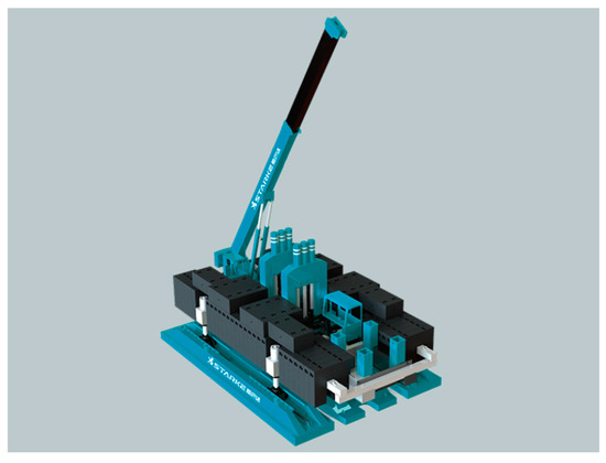
Figure 1.
YZY400 hydraulic static pile driver.
In recent years, with the development of piling technology, hydraulic static pile presses have taken a pivotal role in the construction of pile foundations. However, with the modern demands of green development, energy saving and emission reduction, lightweight vehicles have become a new trend in the development of the manufacturing industry. Product “weight loss” has become the top priority for product design and development in this industry. The lightweight design not only enables efficient product quality and material saving development concepts, but also guarantees product performance. It is also beneficial to enhance the company’s key competitive advantages and major development policies. In order to occupy a favorable position in the international trend of industrial change, China has proposed the “Made in China 2025” strategy in the new international environment. “Made in China 2025” is dedicated to breaking the situation of China’s manufacturing industry being big but not strong, and vigorously carrying out independent research and development. Domestic scholars are working hard to achieve and catch up with the advanced level of the international machinery industry as soon as possible. The pile driver is an integral part of China’s manufacturing [9]. With the improvement of computer technologies, many researchers have gradually mastered some of the advanced software programs such as ANSYS, ABAQUS, MATLAB, and so on. All of these programs can be used for the optimization design of mechanical equipment. The level of mechanical optimization in China has started to improve. By using specific optimization methods, it is possible to optimize multiple objectives with complex linkages at the same time. In this context, the design of pile driving machines is no longer just about achieving the required strength and stiffness of the structure. The aim is also to design mechanical equipment that combines safety and economy. Optimal design methods based on sensitivity analysis have found applications in numerous fields [10] such as automotive, aerospace design, and agricultural machinery. Tang Jing et al. used the structural parameters of commercial vehicle cabs, using thickness as design variables, and applied the sensitivity analysis method to filter out the best variables to achieve the lightweight goal [11]. Wang Li proposed and evaluated a multidisciplinary sensitivity analysis for rotorcraft simulation and applied it to the constrained optimization of rotorcraft configuration [12]. Yu Tongtong et al. proposed a parametric sensitivity analysis of the composite prepreg tape winding process and applied it to the establishment of an optimization method for winding process parameters [13]. Liu Qimao proposed to solve the sensitivity by gradient method and applied it to the lightweight design of combined beams [14]. Kiendl, J. et al. proposed a method for the geometry optimization of shell structures by applying sensitivity weighting [15]. From the literature, it can be seen that the application based on the sensitivity analysis method solves the problem of the optimal design of metal structures such as commercial vehicles and rotorcraft. The optimization of the sensitivity calculation method is also proposed to increase the efficiency of model optimization. However, there has been little research for the application of pile machinery, especially the metal structure of pile machinery. Therefore, the use of an optimal design method for the large body structure of the pile press not only reduces materials waste, but is important to accelerate the realization of the “Made in China 2025” strategy in China.
In this paper, the three-dimensional model of the large body structure of the pile press is established by using the finite element analysis method. Sensitivity analysis was used to optimize the design of the large body structure of the pile press, which minimizes the weight of the large body skeleton structure to meet the strength and stiffness constraints, thereby reducing the production cost [16].
2. Body Model Structure and Analysis
The large body skeleton structure is a key component of the hydraulic static pile driver. Specifically, it is the main load-bearing part of the pile driver. Except for the lower support structure of the pile driver and the walking mechanism, the weight of the rest of the machine is supported by the large body of the pile driver. It enables the pile driver and crane to work properly. In this way, it plays a role in the entire structure of the pile driver. With a large body structure, the motion of the walking and traversing mechanisms will drive the upper parts that cannot move together. Therefore, the design of the large-body skeleton structure plays a crucial role in the working performance and operation of the pile driver.
2.1. Finite Element Model (FEM)
The rapid development of computer technologies has made it possible to use simulation techniques to complete the design and analysis of complex product structures. The finite element method is based on the principle of variability, and is essentially a numerical approximation method. It helps to solve complex engineering problems by approximating the structure as a whole, using a finite number of organic combinations of discrete units. Since the finite element method has a very clear physical concept, this method is also highly suitable for more complex structures. At the same time, the calculations of the finite element method can be implemented by computer and are highly efficient. Currently, the finite element method is widely used in the study of static structural dynamics, fluid analysis, thermal analysis, electromagnetic field analysis and other problem areas. The use of parametric finite element modeling techniques for the modeling, analysis, and optimization of product design is one of the commonly used approaches in engineering practice. A high-precision model construction based on the finite element analysis method is able to recover the true model with relative accuracy. The analysis and design of product batches through parameters considerably improves design efficiency and saves design costs. In this paper, the ANSYS parametric design language provided by the ANSYS finite element analysis software is used to perform computer-aided modeling. The finite element model of the large body structure of the YZY400 hydraulic pile driver is used as the object of study, and all the performance parameters of the pile driver are shown in Table 1.

Table 1.
YZY400 pile driver performance table.
The large body structure of this model of the static pile driver is welded by steel plates and is a complex space box system structure. In order to ensure that the finite element analysis is carried out properly and effectively, the original model is simplified appropriately. Members without load-bearing effects were removed, details such as unnecessary holes and rounded corners were simplified, and legs attached to the bulk structure were simplified. In this paper, in order to facilitate the optimization analysis of the bulk structure based on its properties, we parametrically model it using the ANSYS APDL pc-software(Mechanical APDL 2020 R1, ANSYS, USA). Since the bulk structure belongs to a large thin plate structure, with a large difference between the thickness and the rest of the dimensions, the plate and shell units are chosen to simulate actual steel plates when modeling. The specific type is chosen from the shell 63 in APDL [17]. During the finite element analysis, the transmission of forces relies on the nodes between the units. In order to ensure that the finite element analysis is performed correctly, a proper meshing is particularly important. Therefore, in this paper, the model is meshed in the form of free triangles. The meshing of local locations in the model is shown in Figure 2.
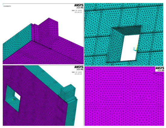
Figure 2.
Large body structure finite element model.
After the establishment of the finite element model of the large body structure, the boundary conditions are applied to the model, and the static analysis is carried out based on the loads that the large body skeleton is subjected to in the actual work.
2.2. Static Analysis
2.2.1. Typical Working Condition Selection
As shown in Figure 3, a hydraulic oil tank and cab, used to power the pile driver for pile extraction and pile pressing, are also mounted on the large body skeleton. The static pile driver works on the pile by means of a pile pressing mechanism. Hydraulic cylinders in the chassis platform provide the power for the pile pressing and pile pulling action.
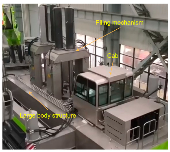
Figure 3.
Hydraulic pile driving mechanism and cab.
The static pile driver operates on the pile through a pile pressing mechanism, powered by hydraulic cylinders in the chassis platform to enable a pile pressing and pile pulling action. The pile pressing mechanism is connected to the large body in the upper part of the massive body skeleton structure. The entire pile driver travels and moves through a travel mechanism and a traverse mechanism in the lower part of the large body platform. The outriggers are bolted to the bulkhead structure, and the outriggers have hydraulic cylinders attached to the long boat by hinges. The ball head of the ball hinge is attached to the slewing mechanism and the short boat. The large body platform structure will link the static pile drivers into a single unit that will directly bear the reaction force when the pile is pressed. The maximum deformation of the bulk structure occurs when the static pile driver implements the pile pressing action. In this paper, we present a hydrostatic analysis of the pile pressing operation and its hydrostatic properties under the most dangerous operating conditions.
2.2.2. Analysis of Stress Results in Typical Working Conditions
The maximum pile-up force of the pile-up driver is 400 t. The combined effect of the maximum pile-up reaction force, and the gravity of the pile-up table itself, has an upward effect on the pile-up driver’s bulk structure. The longitudinal meander mechanism supports the entire structure, and the combined force acts on the connecting surfaces of the cylinder and column in the form of a uniform load q. The calculated load q is 3.061 Mpa, and a diagram of the bulk structure is shown in Figure 4.
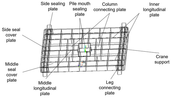
Figure 4.
Large structure component drawing.
In the finite element, the transmission of force is carried out with the help of nodes, so the load can be applied either centrally on the nodes or uniformly on the surface. This calculation applies the load q on the connection surface of the column with the uniform load applied. The large body structure cross-sectional dimension parameters are shown in Figure 5.
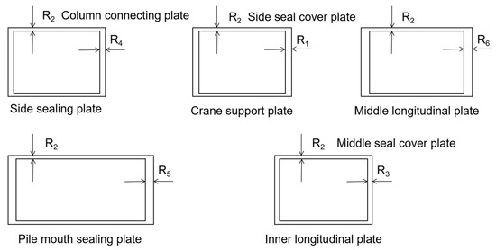
Figure 5.
Section size of large structure.
In the above figure, R1 is the thickness of the crane support plate. R2 is the thickness of the side seal cover plate. R3 is the thickness of the inner longitudinal plate. R4 is the thickness of the side sealing plate. R5 and R6 are the thickness of the pile mouth sealing plate and the middle longitudinal plate, respectively.
In actual operation, the big body structure is lifted on the ground by four cylinders, and the pile is pulled or pressed along the cylinder legs in an up and down direction to complete the working condition. The degrees of freedom of the cylinder legs in other directions are limited, so the big body structure has only one degree of freedom. When the constraints are set for the large body structure model, the degrees of freedom in all directions of the large body structure are restricted, except for the release of the Z-axis degrees of freedom. Therefore, the pile driver is restrained at the connection between the large body structure and the legs. There are 2 degrees of freedom in the translation direction and 3 degrees of freedom in the rotation direction (ROTX, ROTY, ROTZ), as shown in Figure 6.
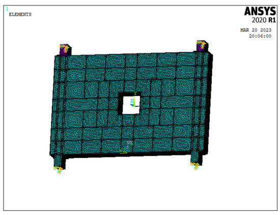
Figure 6.
Large body structure constraint diagram.
The structure was analyzed in ANSYS APDL, and the stress cloud and displacement cloud of the large body skeleton under the compression pile condition were obtained, as shown in Figure 7.
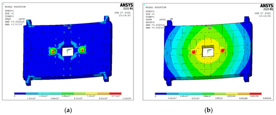
Figure 7.
Large body skeleton stress cloud and skeleton displacement cloud. (a) Large body skeleton stress cloud; (b) large body skeleton displacement cloud.
From Figure 7a, it can be seen that the maximum stress of the big body skeleton is 110 MPa. The maximum stress appears at the connection of the legs of the big body structure, which is consistent with the actual working condition. According to the crane Chinese standard GBT3811-2008, taking 1.34 as the safety factor, the allowable stress of the material is 175 MPa, which meets the design requirements.
As can be seen from Figure 7b, the maximum displacement is 2.01 mm under the pile pressing condition, which meets the requirements. The maximum deformation near the hydraulic cylinder cover plate is also in line with the actual situation.
3. Theoretical Foundations of Sensitivity Analysis
We refer to the gradient of variation of the structural or product performance values with respect to the design variables as sensitivity. The design variables in this paper are the thickness of each plate among the large body structure mentioned above. Changes in the design variables cause changes in the product performance values, such as the mass, strength, and stiffness of the structure. When analyzing the structural stiffness, the gradient of the stiffness variation to the value of the thickness (d) of each plate of the large body is the sensitivity [18]. Mathematically, if F(d) is continuous and derivable, the first-order sensitivity S of this function when Equation (1) exists is:
where: is the performance value of the large body structure, is the design variable of the large body structure.
Finite element analysis theory emphasizes that the general structural static finite element analysis has:
where: denotes the external load vector of the structure, is the displacement vector of the structure. is the total stiffness matrix of the finite element model; n is the degrees of freedom of the structure.
is the partial derivative of with respect to the design variables d. is the partial derivative of with respect to the design variables d. is the derivative matrix of to d, and the derivative of (2) with respect to d is obtained:
If the vector is equal to 0, then there is:
where: is the inverse matrix of the total stiffness matrix of the structural finite element model. The total stiffness matrix of the structural finite element model is obtained after summing the corresponding matrices of each cell, which is:
where: i is the cell number; is the expanded cell stiffness matrix. The derivative of the formula of (6) to d is obtained:
Equation (5) can be replaced by:
where: is the cell stiffness derivative matrix without order expansion, ni is the cell degrees of freedom. is the component of the corresponding unit i in , which is the vector of the individual unit displacements. Then, the formula of (8) is required to calculate the sensitivity of the structural displacement vector to the design variable d. In the optimization analysis of the large body skeleton structure, the large body finite element model is composed of plate and shell units. Therefore, the unit stiffness matrix before the expansion of the plate and shell units is:
where: E is the modulus of elasticity of the material, d is the real constant of the plate and shell unit, which is the thickness of the plate. and are the membrane stiffness and bending stiffness of the plate in the stiffness of the shell unit. While the coordinates of each node in the cell of i are related to and , they are not related to the modulus of elasticity E and the thickness of the plate d, and as we know:
Therefore, the value of can be obtained by performing only one more calculation of the stiffness matrix of each cell.
4. Optimized Design of Structures
4.1. Sensitivity Analysis
The mass of the large body skeleton of a pile driver is related to the mass of each of the thin plates that make up its structure. For thin slabs, the dimensional properties that affect their mass are dominated by the thickness of the slabs. Therefore, the sensitivity analysis of the bulk skeleton structure to the thickness of each slab is the main consideration. The results of the sensitivity calculation are typically derived from the design of experiment analysis [19]. The experimental factors that have a big effect on the performance of the skeleton structure can be obtained by screening from several design variables. The sensitivity calculation method can be used to achieve a reasonable allocation of materials, so as to improve the light weight of the large body structure. The influence of the change of the design parameters of the large body skeleton structure on the performance and extent of the large body structure are quantitatively studied. Then, the parameters that are most sensitive to the response of the large body structure performance in the optimization design process will be screened out. In turn, the optimal range of variables for optimal design is obtained, and the optimal design variables are further extracted. The sensitivity analysis of the large body structure of the pile driver in the most dangerous working conditions involves the large body strength, stiffness and total mass of the large body structure of the pile driver. Considering that the large body structural members are all thin steel plates, the thickness of large body plates is selected as the structural design variable. Sensitivity analysis is performed for the maximum stress at the nodes of the large body structure, the maximum displacement, and the mass of the large body skeleton of the pile driver.
Design of experiment is computed analytically using an iterative approach, and for experiments, the maximum and minimum values of the design variables, that is, the upper and lower limits, must be determined. After consulting with relevant technical experts, R1 is taken as between 0.03 m and 0.05 m, R2 is taken as between 0.02 m and 0.04 m, R3 is taken as between 0.025 m and 0.045 m, R4 is taken as between 0.025 m and 0.045 m, R5 is taken as between 0.04 m and 0.06 m, and R6 is taken as between 0.05 m and 0.07 m. There are numerous commonly used experimental design methods, such as Central Composite [20,21,22], Fractional Factorial, Full Factorial, Latin Hypercube, Orthogonal Array, Sobol Sequence, etc. The Latin square experimental method is a sampling method based on the principle of equal probability or equal distance for multidimensional stratified sampling by constraining the locations of sample points. It allows the sample points to be distributed more evenly throughout the design space. Compared with other experimental methods, the advantage of this sampling method is that it has a sampling memory function, which can avoid repeated sampling. The Latin square experimental method can cover the whole design space with a smaller number of sample points, so as to efficiently obtain more comprehensive spatial information. Moreover, this sampling method does not require too much for the number of sample dimensions and sample points. Therefore, in order to obtain sample points for experimental design more efficiently and comprehensively, this paper adopts the Latin square experimental method to obtain data on the variation of each performance value of the large body structure with independent variables [23]. The sensitivity analysis results of the thickness of the large body structure’s steel plate to the mass, displacement and structural stress were obtained after the arithmetic analysis, as shown in Table 2, Table 3 and Table 4.
Table 2.
Sensitivity analysis of mass to plate thickness.
Table 3.
Sensitivity of displacement to plate thickness.
Table 4.
Sensitivity analysis of stress to plate thickness.
Combined with the results of the sensitivity analysis of the design parameters, the parameters that have a greater impact on weight reduction, but have a minor impact on the stiffness and strength of the large body structure, are selected as design variables. Therefore, R1, R3~R6, a total of five parameters, are selected as design variables [24].
4.2. Constructing Optimal Design Model
- (1)
- Design variables: The large body skeleton of the pile driver is mainly made of thin steel plates welded together, and the steel plate thickness R is chosen as the design variable.
- (2)
- Constraints: The strength and stiffness of the large body skeleton are the constraints.
- (3)
- Objective function: The large body skeleton mass M is minimized as the objective.
An optimization mathematical model is developed as follows:
where: is the thickness of the plate, n is the number of variables, is the maximum stress obtained by calculation, is the maximum deflection obtained by calculation, and M is the mass of the large body structure.
ISIGHT software is a “software robot” that can quickly integrate and couple various software by building blocks. It includes specialized integration components for various CAE software such as Abaqus, CATIA, SolidWorks, ANSYS, MATLAB, etc. ISIGHT can also integrate various software that cannot be used directly through the common integration component SIMCODE for efficient and quick simulation. By integrating ANSYS APDL parametric language design programs, Windows batch files and output files into ISIGHT, calls to ANSYS can be implemented. In this paper, a workflow consisting of an optimization calculation component and a call to the SIMCODE component of the ANSYS APDL software is used to perform the optimization model calculation. As shown in Figure 8, a circular workflow of SIMCODE and optimization is created in ISIGHT.
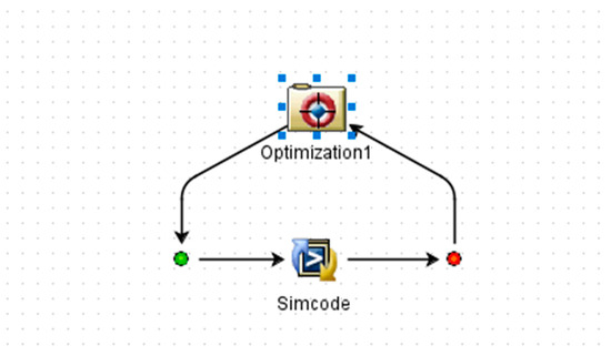
Figure 8.
ISIGHT workflow diagram.
In engineering practice, there are three main types of optimization algorithms: direct search, gradient optimization, and global optimization algorithms. The pointer algorithm is actually a library of algorithms. During the optimization process, the pointer algorithm automatically captures information about the design space, and automatically combines four of the three types of optimization algorithms to form an optimal strategy. During computation, the algorithm can switch between the four algorithms and continue to find a better design solution as long as it is still running. Therefore, in order to find a better optimal solution for the optimization mathematical model and to use the minimum number of optimization computation simulations, this paper adopts the pointer algorithm for solving the optimization mathematical model [25].
5. Results
After calculation, the variable values, maximum stress, maximum displacement and structural mass of the optimization process can be obtained, as shown in Figure 9. The thickness of the design variables before and after optimization and the rounded thickness after optimization are shown in Table 5. The comparison results of mass, maximum stress and maximum displacement of the structure before and after optimization are shown in Table 6.
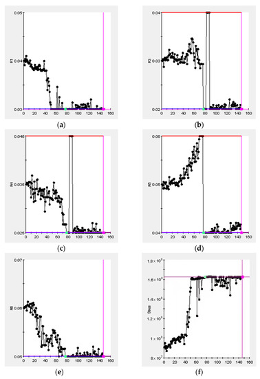
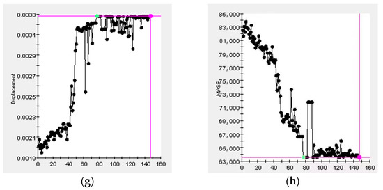
Figure 9.
The value of each variable in the optimization. (a) The value of R1; (b) the value of R3; (c) the value of R4; (d) the value of R5; (e) the value of R6; (f) the value of stress; (g) the value of displacement; (h) the value of mass.
Table 5.
Design variables before and after optimization and rounding thickness after optimization.
Table 6.
Comparison of structural stress and displacement before and after optimization.
In practice, design variables are always subject to artificial influences that lead to uncertainty. Uncertainty often makes the optimal solution beyond the feasible range, and it eventually becomes infeasible. Moreover, the complex structure of the pile driver makes it difficult to directly design the dimensions of each design variable, and judge whether the design requirements are satisfied. As shown in Table 5, the values of each variable are well optimized and satisfy the respective value ranges. Therefore, the method of constructing parametric modeling, building a mathematical model, and finding the optimal solution is to satisfy the expected effect of the design.
As can be seen from Table 6, the maximum stress value of the large body skeleton is 110 MPa under pile compression before optimization and 162 MPa after optimization. With a safety factor of 1.34 and a maximum safe stress value of 175 MPa, the optimized stress value still has a large margin and thus meets the design requirements. The maximum displacement is increased to 3.26 mm before and after optimization, compared to 2.01 mm before optimization. However, there is still a large excess for the stiffness condition for large body structures. It can be seen that the optimized structure satisfies the design requirements. At the same time, the mass of the optimized large body structure was reduced from 82,556.1 kg to 64,282.6 kg before optimization, which is in line with the optimization goal of reducing the structural mass in this paper.
6. Conclusions
In this paper, the typical working conditions of a pile press are used as an example to study how to improve the light weight of the large body structure of a static pile press. This paper first aimed to develop a finite element model of the large body structure of a static pile driver. The strength and stiffness of the large body of the pile driver were verified through finite element analysis to meet the design requirements. On this basis, the structure optimization based on sensitivity analysis was carried out. A mathematical analytical model of the optimization was constructed, and the results of the optimization showed that the strength and stiffness of the optimized large body structure of the hydrostatic pile driver are within reasonable limits. Therefore, the hydrostatic pile driver has great safety and reliability, which can completely ensure the safety of the pile driver during the working process. Compared to the mass of the preoptimized bulk structure, which was 82,556.1 kg, the optimized bulk structure has a mass of 64,282.6 kg, a 22.1% reduction in mass. It reduces the production cost and has some guiding implications for future lightweight designs of piling machinery. The shortcoming of this paper is that the effectiveness of various single optimization algorithms for solving the mathematical model of the large body structure is not verified due to time constraints. In future research work, the construction of some optimization algorithms such as genetic algorithm, particle swarm algorithm, etc. and the comparison of their respective optimal solutions will be added.
Author Contributions
Conceptualization, J.W.; methodology, Y.Y.; software, Y.Y.; validation, Y.Y.; formal analysis, J.W.; investigation, J.H.; resources, J.H.; data curation, J.H.; writing—original draft preparation, Y.Y.; writing—review and editing, Y.Y.; visualization, Y.Y.; supervision, J.W.; project administration, J.W.; funding acquisition, J.W. All authors have read and agreed to the published version of the manuscript.
Funding
This research was supported by key scientific research projects of colleges and universities in Henan Province and funded by School of Mechanical Engineering, North China University of Water Resources and Electric Power. (Grant No. 17A460020).
Institutional Review Board Statement
Not applicable.
Informed Consent Statement
Not applicable.
Data Availability Statement
Not applicable.
Conflicts of Interest
The authors declare no conflict of interest.
References
- Sfiligoj, E. Pile drivers. Croplife 2010, 1736, 86–89. [Google Scholar]
- Liew, S.S.; Ho, S.F. Fallacy of capacity performance & innovation improvement of jack-in piling in Malaysia. Geotech. Eng. 2016, 47, 134–143. [Google Scholar]
- Noor, S.T.; Islam, M.S.; Mumtarin, M.; Chakraborty, N. Dynamic load test of full-scale pile for the construction and rehabilitation of bridges. IOP Conf. Ser. Mater. Sci. Eng. 2019, 513, 12017. [Google Scholar] [CrossRef]
- Ai, Z.; Gu, G.; Li, P. Analysis of interaction between fractional viscoelastic saturated soils and laterally loaded pile groups. Yantu Lixue/Rock Soil Mech. 2022, 43, 2933–2940. [Google Scholar]
- Worku, A.; Lulseged, A. Kinematic pile-soil interaction using a rigorous two-parameter foundation model. Soil Dyn. Earthq. Eng. 2023, 165, 107701. [Google Scholar] [CrossRef]
- Hama, K.; Horii, Y.; Nakanishi, Y.; Watanabe, T. Field trials of large-diameter multi-belled piling method. In Geotechnics for Sustainable Infrastructure Development; Springer: Singapore, 2020; pp. 161–168. [Google Scholar]
- Jiang, Y.; Xu, C.; Shao, S. Analysis on the piling mechanism of the jacked pile in layered soil. Arab. J. Geosci. 2022, 15, 1399. [Google Scholar] [CrossRef]
- Hisao, Y.; Hisashi, H.; Masanori, K. Challenges in the past and for the future of design and installation technologies on steel pipe piles in Japan. Doboku Gakkai Ronbunshuu F 2010, 663, 34–36. [Google Scholar]
- ZuoJian, D. Research on Lightweight Technology of YZY800D Pile Driver Frame Structure; Southwest Jiaotong University: Chengdu, China, 2015; Available online: https://kns.cnki.net/ (accessed on 30 August 2022).
- Lim, G.T. Applications of press-in piling in south-east asia countries. Spec. Present. 4th IPA Int. Workshop 2012, 12, 6–7. [Google Scholar]
- Tang, J.; Song, C.; Liu, F.Y.; Xu, Y.E. Research on lightweight method of commercial vehicle cab based on structural parameter sensitivity analysis. Mech. Des. 2021, 38, 97–101. [Google Scholar]
- Wang, L.; Diskin, B.; Biedron, R.T.; Nielsen, E.J.; Bauchau, O.A. High-Fidelity Multidisciplinary Sensitivity Analysis and Design Optimization for Rotorcraft Applications. AIAA J. 2019, 57, 3117–3131. [Google Scholar] [CrossRef]
- Yu, T.; Shi, Y.; He, X.; Kang, C.; Deng, B.; Song, S. Optimization of Parameter Ranges for Composite Tape Winding Process Based on Sensitivity Analysis. Appl. Compos. Mater. 2017, 24, 821–836. [Google Scholar] [CrossRef]
- Liu, Q.M. Exact sensitivity analysis of stresses and lightweight design of Timoshenko composite beams. Compos. Struct. 2016, 143, 272–286. [Google Scholar] [CrossRef]
- Kiendl, J.; Schmidt, R.; Wüchner, R.; Bletzinger, K.U. Isogeometric shape optimization of shells using semi-analytical sensitivity analysis and sensitivity weighting. Comput. Methods Appl. Mech. Eng. 2014, 274, 148–167. [Google Scholar] [CrossRef]
- Liu, S.H.; Du, Y.B.; Lin, M. Study on lightweight structural optimization design system for gantry machine tool. Concurr. Eng. Res. Appl. 2019, 27, 170–185. [Google Scholar] [CrossRef]
- Jun, P.; Hu, H.; Dong, Z.; Li, K.J. Stress Research and Finite Element Analysis of Pile Clamping Mechanism of Hydraulic Static Pile Driver. Adv. Mater. Res. 2014, 3103, 908. [Google Scholar]
- Xiong, F.; Wang, D.; Ma, Z.; Chen, S.; Lv, T.; Lu, F. Structure-material integrated multi-objective lightweight design of the front end structure of automobile body. Struct. Multidiscip. Optim. 2018, 57, 829–847. [Google Scholar] [CrossRef]
- Zhang, C.; Li, Q.; Zhang, X.; Wang, X.; Chen, J.; Shen, X. Lightweight Design of Special Axle Hub Based on ANSYS Consider Different Working Conditions for Low Carbon. Math. Probl. Eng. 2022, 2022, 3738996. [Google Scholar] [CrossRef]
- Wu, M. Design Research of Crawler Type Multifunctional Static Pile Driver; Northeast Petroleum University: Daqing, China, 2017; Available online: https://kns.cnki.net/ (accessed on 30 August 2022).
- Ning, H.E.; Delong, Z.; Qinghua, Z. Reliability Sensitivity Analysis for Drum Brake on Modal Stress. Int. J. Plant Eng. Manag. 2021, 26, 193–214. [Google Scholar]
- Zuo, W.; Yu, J.; Saitou, K. Stress sensitivity analysis and optimization of automobile body frame consisting of rectangular tubes. Int. J. Automot. Technol. 2016, 17, 843–851. [Google Scholar] [CrossRef]
- Jin, W.; Mao, Z.; Zhou, S.; Zhang, T.; Hu, Y.; Wu, Z. Research on Multi-Optimal Project of Outlet Guide Vanes of Nuclear Grade Axial Flow Fan Based on Sensitivity Analysis. Appl. Sci. 2022, 12, 3029. [Google Scholar] [CrossRef]
- Sha, L.; Lin, A.; Zhao, X.; Kuang, S. A topology optimization method of robot lightweight design based on the finite element model of assembly and its applications. Sci. Prog. 2020, 103, 36850420936482. [Google Scholar] [CrossRef] [PubMed]
- Zhu, H. Study on the Strength and Fatigue Life of ZYB800M Pile Press Clamp Pile Box; Central South University: Changsha, China, 2014; Available online: https://kns.cnki.net/ (accessed on 30 August 2022).
Disclaimer/Publisher’s Note: The statements, opinions and data contained in all publications are solely those of the individual author(s) and contributor(s) and not of MDPI and/or the editor(s). MDPI and/or the editor(s) disclaim responsibility for any injury to people or property resulting from any ideas, methods, instructions or products referred to in the content. |
© 2023 by the authors. Licensee MDPI, Basel, Switzerland. This article is an open access article distributed under the terms and conditions of the Creative Commons Attribution (CC BY) license (https://creativecommons.org/licenses/by/4.0/).