Article

Shock Wave Formation and Cloaking in Hyperelastic Rods

by
Sergey V. Kuznetsov
Institute for Problems in Mechanics RAS, Moscow 129337, Russia
Appl. Sci. 2023, 13(8), 4740; https://doi.org/10.3390/app13084740
Submission received: 17 March 2023 / Revised: 31 March 2023 / Accepted: 4 April 2023 / Published: 10 April 2023
(This article belongs to the Section Acoustics and Vibrations)

Abstract

:
The analysis of propagating an initially harmonic acoustic pulse in a semi-infinite hyperelastic rod obeying the Yeoh strain energy potential reveals attenuation with distance of the wave amplitudes caused by the elastic energy dissipation due to forming and propagation of the shock wave fronts and heat production. The observed attenuation of harmonic waves results in a broadband cloaking of fairly remote regions. The analysis is based on solving a nonlinear equation of motion by an explicit Lax–Wendroff time-difference scheme combined with the finite element discretization in the spatial domain. The revealing phenomena are applicable to studies of acoustic wave propagation in various elastomeric rubberlike materials modeled by the Yeoh hyperelastic potentials.

1. Introduction

1.1. An Overview

(A) Shock waves in fluid and gaseous media. The first works on the formation of acoustic shock wave fronts in gaseous media descend to Rankine [1] and Vieille [2]. It was found that at a moving surface of a weak discontinuity, known also as the weak shock wave front, the thermodynamic equations should be taken into consideration to account for the heat production. Later, a complete theory for the formation and propagation of shock wave fronts in gaseous and liquid media was developed [3,4,5,6,7,8,9,10,11,12,13,14,15,16].
Several numerical methods for analyzing the propagation of shock wave fronts were developed: (i) the shock-fitting method [17], and (ii) the non-linearization techniques [18,19]. Both methods, along with (iii) the finite difference methods [20,21,22,23], (iv) the finite element methods [24,25,26], and (v) various types of the discrete element approaches [27,28,29], are widely used in the study of acceleration waves. Note also that according to [30], the shock waves in gaseous and liquid media propagate with faster velocities than the local sound velocity.
(B) Shock waves in solids. The first theoretical works on the formation and propagation of shock waves in elastic–plastic solids are mainly due to von Karman, who gave an explicit representation for the displacement of the initial part of the propagating pulse in a semi-infinite rod [31]:
u ( x , t ) = c 0 t + x / c shock
where c shock is the unknown shock wave velocity; t is the time; and x is the distance from the rod edge.
u ( x , t ) x = 0 = c 0 t
The last equation defines c 0 as the velocity of the impact applied at the rod edge. It was found that (i) the c shock  velocity depends upon c0; (ii) it depends upon actual strain; and (iii) the shock wave velocity in an elastic–plastic target slab may be larger than the impact velocity [32,33]:
c shock c 0
It should be mentioned that in physical experiments [32,33], inequality Equation (1c) was obtained by indirect measurement of the particle velocities at the rear face of the slab. In this respect, see previous studies [34,35,36,37,38,39,40]. Most of these works are concerned with elastic–plastic solids of the Prandtl–Reuss type. However, despite a significant achievement in finding the shock wave velocity, the problem of mechanical energy dissipation and heat production remained unresolved; meanwhile, physical experiments revealed a substantial temperature rise [33].
Hill [41] proposed, for the first time, a comprehensive theory of shock waves in hypoelastic solids satisfying the following equation of state:
τ ˙ = C ( ε ) ε ˙
where τ ˙ is the Kirchhoff stress rate; C is the fourth-order elasticity tensor, assumed to be positive definite; and ε ˙ is the infinitesimal strain rate. For such a hypoelastic material, the shock wave front velocity could be explicitly constructed [34,35,42].
c shock = v n ε n n
where v is a jump in the velocity field; and ε is a jump in the corresponding strain field. Note that for shock waves in a 1D rod, Equation (1e) reduces to:
c shock = v / ε
According to Equation (1e), the shock wave velocity depends upon the jump in velocity and strain and the inclination of the jump with respect to the unit normal, ensuring c shock 0 ;   [43].
A large number of works [44,45,46,47,48,49,50,51] are concerned with the analyses of the formation and propagation of shock waves in bi-modular elastic materials with the following dependence of the elastic modulus on infinitesimal strain:
E ( ε ) = E 0 ( 1 α ε )
where E 0 is the median modulus; and 0 < α < 1 is a dimensionless parameter specifying the jump in E at transition from negative to positive strain. Harmonic excitation applied to the left end of a semi-infinite rod revealed a substantial decrease in wave amplitudes with distance from the edge due to the formation of multiple shock wave fronts, and hence the loss of mechanical energy, which ensures cloaking of objects that are sufficiently distant from the applied excitation load [51]. Another remark concerns the possible formulation of cloaking effects for nonlinear waves in viscoelastic media in terms of fraction derivatives [52,53].

1.2. Problem Statement

The current research is concerned with studying the propagation of an initially harmonic wave in a semi-infinite hyperelastic rod with a continuous dependence of elastic properties on strain, defined by the Yeoh potential; see Figure 1. The Yeoh potential is known for its almost perfect fit of experimental stress–strain data for a large number of elastomers [54]. It is widely used for modeling the stress–strain behavior of various cross-linked polymers, especially those used in vibration absorbers [55,56], seismic isolation devices [57], and biological tissues [58].
In the course of the analytical and numerical studies, it was observed, apparently for the first time, that (i) multiple shock wave fronts are formed and propagate; (ii) wave amplitudes decrease with distance from the edge of the rod; (iii) the specific strain energy decreases with distance with a simultaneous increase in thermal energy; (iv) the speed of propagating shock wave pulses satisfies Equation (1f); and (v) attenuation and, hence, heat generation is heavily dependent on the time–frequency and amplitude of the loading. The observed phenomena may result in a better understanding of the acoustic wave attenuation in various polymer materials, which is caused by the formation and propagation of shock wave fronts. In summary, the observed attenuation of harmonic waves results in a broadband cloaking of fairly remote regions.
The performed analysis is based on a combination of Cauchy formalism for constructing a secular equation for travelling waves [59,60,61,62] and the Lax–Wendroff explicit numerical scheme for numerical solution of the secular equation [63,64].

2. Yeoh Equation of State

2.1. Basic Relations

Considering the left Cauchy–Green deformation tensor:
B = F F t
where F is the strain gradient. The three principal invariants of tensor B are as follows:
I B = tr ( B ) ;   I I B = 1 2 tr ( B ) 2 tr ( B 2 ) ;   I I I B = det ( B )
Denoting principal stretches of the strain gradient, F , as λ k ,   k = 1 , 2 , 3 , gives:
I B = λ 1 2 + λ 2 2 + λ 3 2 ;   I I B = λ 1 2 λ 2 2 + λ 2 2 λ 3 2 + λ 1 2 λ 3 2 ;   I I I B = λ 1 λ 2 λ 3
In the considered case of uniaxial extension and incompressibility, the principal stretches become:
λ 1 = λ ;   λ 2 = λ 3 = λ 1 / 2
Finally, combining Equations (2c) and (2d) yields:
I B = λ 3 + 2 λ ;   I I B = 2 λ 3 + 1 λ 2 ;   I I I B = 1
The left Cauchy–Green deformation tensor admits the following representation in terms of its principal stretches and eigenvectors e k ,   k = 1 , 2 , 3 :
B = λ 2 e 1 e 1 + 1 λ e 2 e 2 + e 3 e 3

2.2. Hyperelastic Potential

The Yeoh hyperelastic potential has the following form [65]:
W = k = 1 n A k I B 3 k
where n is the order with respect to I B ; and A k ,   k = 1 , 2 , , n are unknown coefficients obtained by fitting the experimental data. Note that the original Yeoh [54] work suggested using the third-order polynomials with respect to I B . At n = 1 , the Yeoh potential turns into the neo-Hookean potential [66]. Substituting Equation (2e) into potential Equation (2g) gives for the uniaxial extension a polynomial form with respect to λ for the Yeoh potential:
W ( λ ) = k = 1 n A k λ 3 3 λ + 2 λ k
The last expression shows that W ( λ ) is a polynomial of order 3 n .
Let ε be principal strain along the e 1 -direction, thus ε = λ 1 . In terms of ε , the Yeoh potential becomes:
W ( ε ) = k = 1 n A k ε 2 ε + 3 ε + 1 k
The last two expressions for W will be used in the subsequent analysis.

2.3. Stress–Strain Relation

For the considered case, the Cauchy stress component, τ 11 , with the omitted indices is given by the following expression:
t ( λ ) λ λ W ( λ )
which in view of Equation (2h), yields:
τ ( λ ) = k = 1 n A k 2 k ( λ 2 + λ + 1 ) ( λ 3 3 λ + 2 ) k ( λ 2 + λ 2 ) λ k
or in terms of principal strain:
τ ( ε ) = k = 1 n A k 2 k ( ε 2 + 3 ε + 3 ) ( ε + 3 ) k ε 2 k 1 ( ε + 3 ) ( ε + 1 ) k
Note, that τ ( ε ) is defined up to the applied pressure.

2.4. Tangent Elastic Modulus

The tangent modulus is defined as:
E ( ε ) = ε τ ( ε )
from where with account of Equation (2l), it follows:
E ( ε ) = ( ε 2 + 3 ε + 3 ) ( ε 2 + 2 ε + 2 ) ( ε + 1 ) 2 A 1 + 2 A 2 ε 2 ( ε + 3 ) ( ε + 1 ) + 3 A 3 ε 4 ( ε + 3 ) 2 ( ε + 1 ) 2 +

2.5. Rod Velocity

It is known that the speed of a pulse propagating in a 1D rod is given by the following relationship [67,68,69]:
c ( ε ) ρ 1 E ( ε ) = ( ε 2 + 3 ε + 3 ) ( ε 2 + 2 ε + 2 ) ρ ( ε + 1 ) 2 A 1 + 2 A 2 ε 2 ( ε + 3 ) ( ε + 1 ) + 3 A 3 ε 4 ( ε + 3 ) 2 ( ε + 1 ) 2 +
Note that the rod velocity coincides with the low-frequency limiting velocity of Pochhammer–Chree waves propagating in a rod of finite radius [67,68].

3. Secular Equations

3.1. Equation of Motion

The equation of motion for a 1D rod may be written in the form:
t t 2 u ( x , t ) = ρ 1 x τ ( ε )
where u ( x , t ) is the displacement field and ρ is the material density. The field u ( x , t ) is assumed to be of class C 1 with respect to x and t variables, and having piecewise continuous second-order derivatives with respect to x and t . In Equation (3a), the displacement field relates to the principal strain by the Cauchy equation:
ε ( x , t ) = x u ( x , t ) 1 + 1 2 x u ( x , t )
t t 2 u ( x , t ) = ρ 1 ( ε 2 + 3 ε + 3 ) ( ε 2 + 2 ε + 2 ) ( ε + 1 ) 2 ×   A 1 + 2 A 2 ε 2 ( ε + 3 ) ( ε + 1 ) + 3 A 3 ε 4 ( ε + 3 ) 2 ( ε + 1 ) 2 + x 2 u ( x , t ) 1 + x u ( x , t )

3.2. Boundary and Initial Conditions

The harmonic force loading boundary condition applied at the left edge of the rod is as follows:
τ ( x , t ) x = 0 = p 0 exp ( i ω t )
where p 0 is the force amplitude, and ω is circular amplitude. At the right end at x , the Sommerfeld attenuation condition [69] is imposed:
u ( x , t ) x = 0 ;   x u ( x , t ) x = 0
Homogeneous initial conditions are imposed on the rod:
u ( x , t ) t = 0 = 0 ;     t u ( x , t ) t = 0 = 0   x

3.3. Energy Balance

Equation of state Equation (2i), along with equation of motion Equation (3c) and boundary and initial conditions Equations (3d)–(3f), should be accomplished by the equation of energy balance [70,71,72]:
0 t P ( τ ) d τ = E k + E s + 0 0 t Q ( x , τ ) d τ d x
where P ( τ ) is the power of force loading defined as:
P ( τ ) = p ( τ ) u ˙ ( 0 , τ )
E k and E s are kinetic and strain energies, respectively:
E k = 1 2 0 t 0 ρ u ˙ ( x , τ ) 2 d x d τ ;   E s = 1 2 0 t 0 W ε ( x , τ ) d x d τ
and Q ( x , τ ) is the specific heat generated at the shock wave propagation. Note that the sign of Q ( x , τ ) in Equation (3g) differs from that introduced previously [70].

3.4. FE Formulation

The governing equations are solved by the 1D FE method for spatial discretization and the FD method in the time–domain coupled with an explicit Lax–Wendroff energy conservation numerical scheme. To achieve a conditionally stable numerical algorithm, the Courant–Friedrichs–Lewi condition was imposed on the time increment Δ t :
Δ t < Δ x max c ( ε )
where Δ x is the spatial increment (mesh size); and c ( ε ) is the rod velocity, defined by Equation (2o). For example, considering a particular case of Yoeh potential that relates to a Neo-Hookean material at n = 1 in Equation (2o), and a fairly large strain interval 0.5 < ε < 0.5 , gives:
max c ( ε ) 2.958 ρ 1 A 1
At n > 1 expression for max c ( ε ) will depend upon ratios A k / A 1 ,   k = 1 , , n , provided A 1 0 .
For spatial discretization, 2-node linear truss elements with no flexural or torsional stiffness were used. The total number N of elements varied in the range 8 K N 24.8 K . The mesh convergence analysis revealed almost identical displacement fields for the mesh with N 10.2 K . Thus, N = 10.2 K was adopted for performing computations in the next section. Another remark regards the use of a median filter to reduce non-physical oscillations:
f * ( t i ) = 1 2 m + 1 k = 1 m f ( t i ± k )
Herein, 2 m + 1 is the filter order; f is the unfiltered function; f * the filtered function. In the next section, median filters of orders 7 ÷ 15 are used.
Finally, the adopted physical nonlinearity prevents the use of a non-reflecting boundary condition at the right end of a rod of finite length; Figure 1. Thus, to eliminate waves reflected from the right end and arriving to a point of observation located at a distance l from the left end, the rod length L should satisfy the following condition:
l min c ( ε ) < 2 L l max c ( ε )
ensuring that the slowest pulse reaches the point of observation without interfering with the fastest pulse reflected from the right end.

4. Numerical Analyses

4.1. The Model

Following [27,73], consider the Yeoh potential Equation (2g) with n = 3 and the following coefficients:
A 1 = 0.27337 ;   A 2 = 0.06226 ;   A 3 = 0.01874
These values for A k ,   k = 1 , 2 , 3 are given in MPa. The material Equation (4a) is used for elastomeric bearings [55]. The material density is taken as ρ = 1520   kg / m 3 .
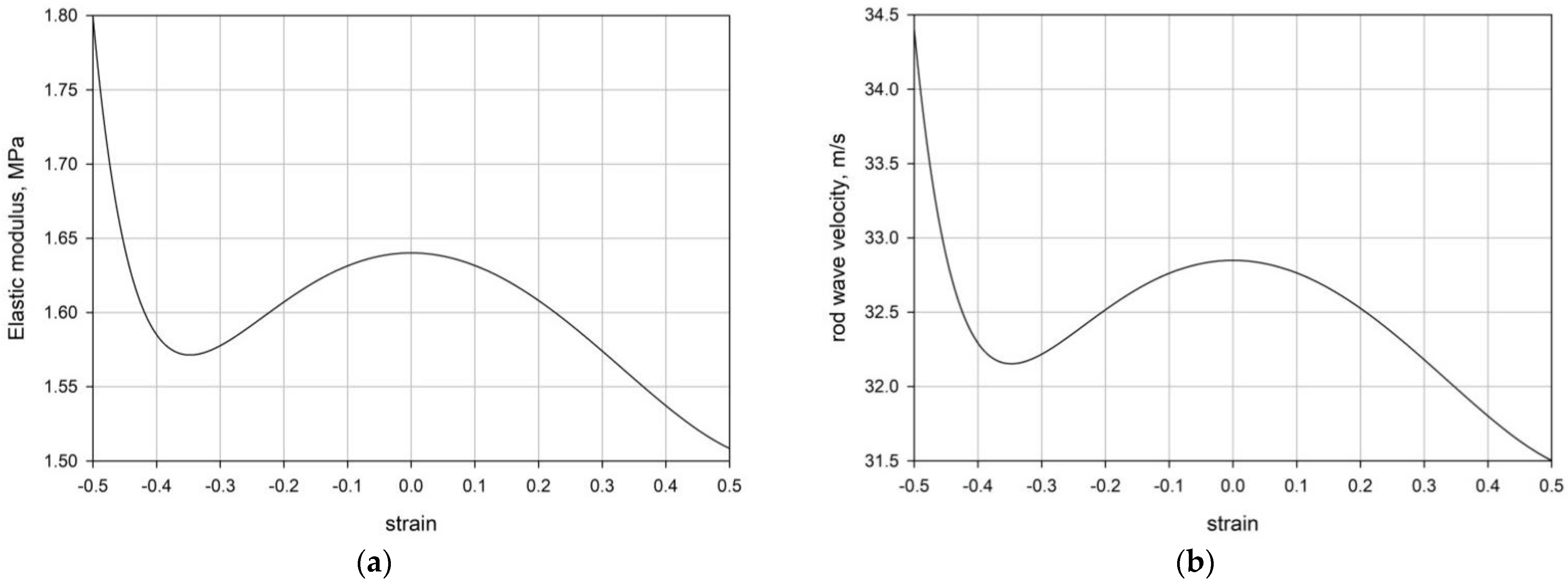
With these parameters, the plots for the tangent elastic modulus vs. strain, defined by Equation (2n), and the rod velocity vs. strain, defined by Equation (2o), are shown in Figure 2.
The plots in Figure 2 show the non-monotonic behavior of both the tangent elastic modulus and the rod velocity in the studied interval 0.5 < ε < 0.5 . Even more important are local maxima at ε = 0 , which ensure the degradation of wave pulses due to the higher propagation velocity at smaller |ε|. Another observation of plot in Figure 2b reveals:
min c ( ε ) ε = 0.5 = 31.5 ;   max c ( ε ) ε = 0.5 34.5
Herein, a rod of finite length L is analyzed with points of observation marked as x 0 , , x 3 ; see Figure 3. The foremost from the left end point x 3 is located at a distant l 3 satisfying relation Equation (3m), ensuring absence of the interactions with the reflected waves from the right end.

4.2. Harmonic Excitations

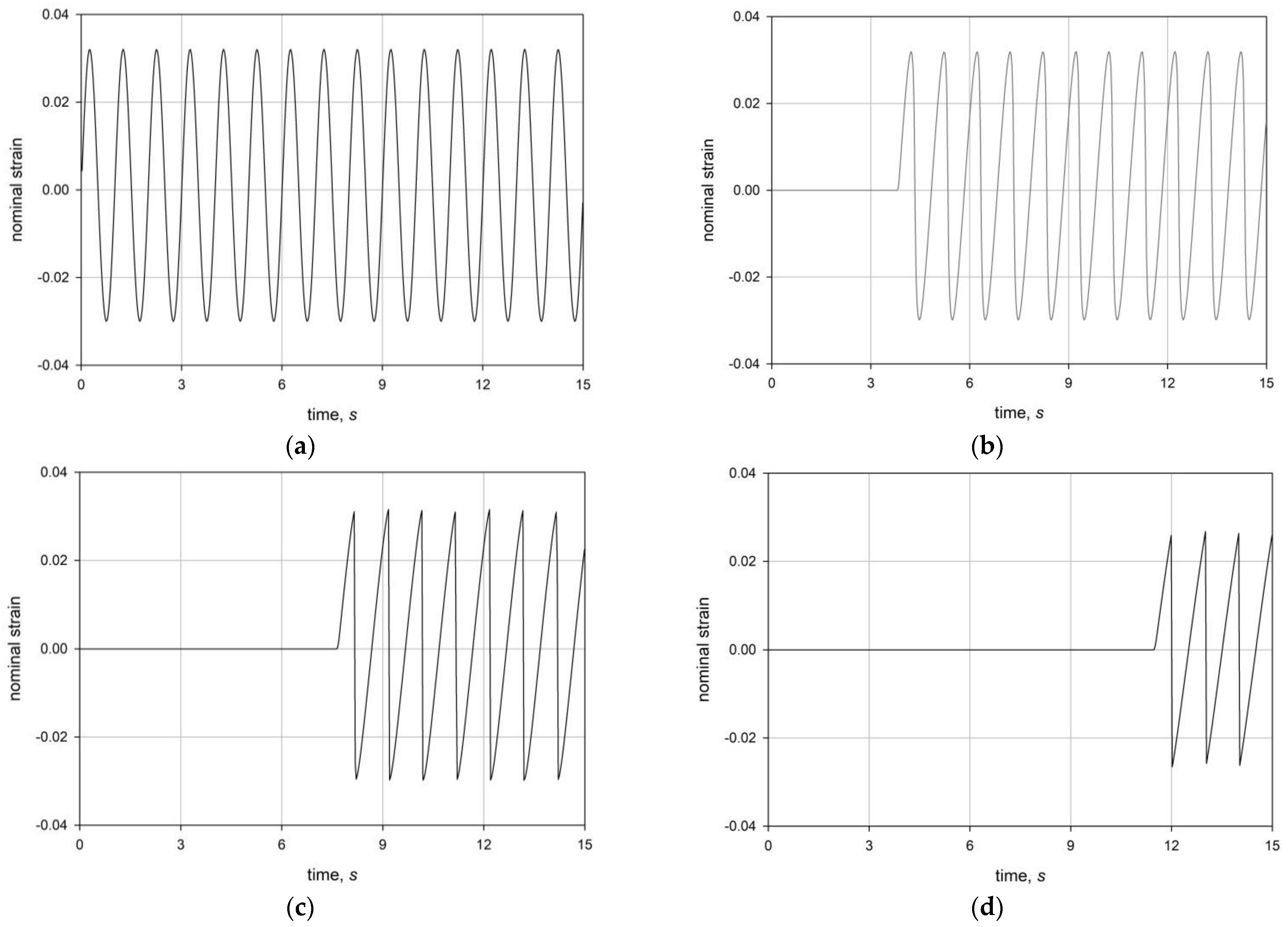
To achieve harmonic force excitation and large strain in a range of frequencies 10 1 f 10 2   Hz and with force loading amplitudes varying in a range 50 p 0   400   KN . The typical plots for strain varied with time are shown in Figure 4 for p 0 = 50   KN .
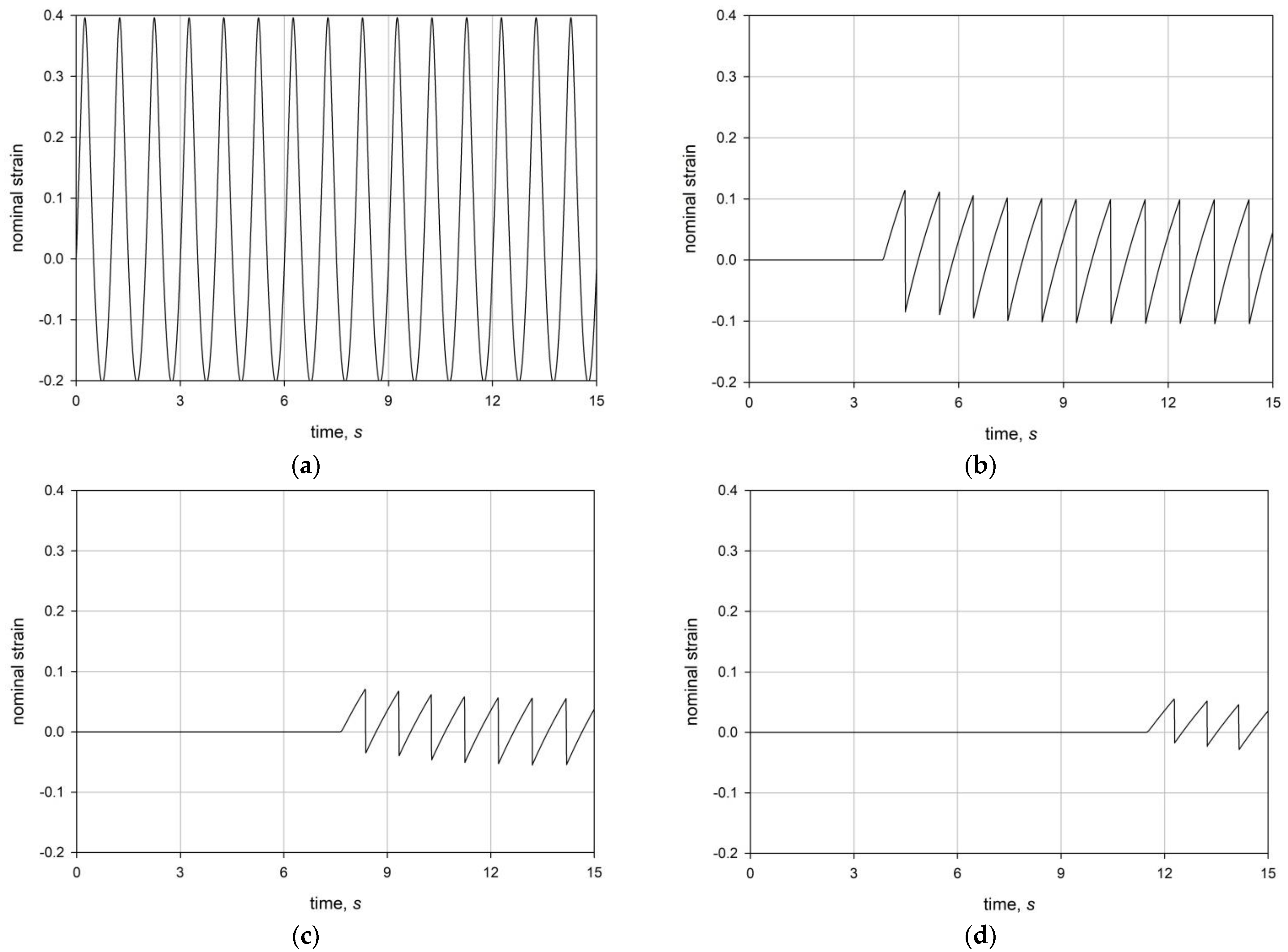
The analogous plots are shown in Figure 5 for p 0 = 400   KN ; this loading amplitude produces an oscillating strain with much larger amplitude, see Figure 5a.
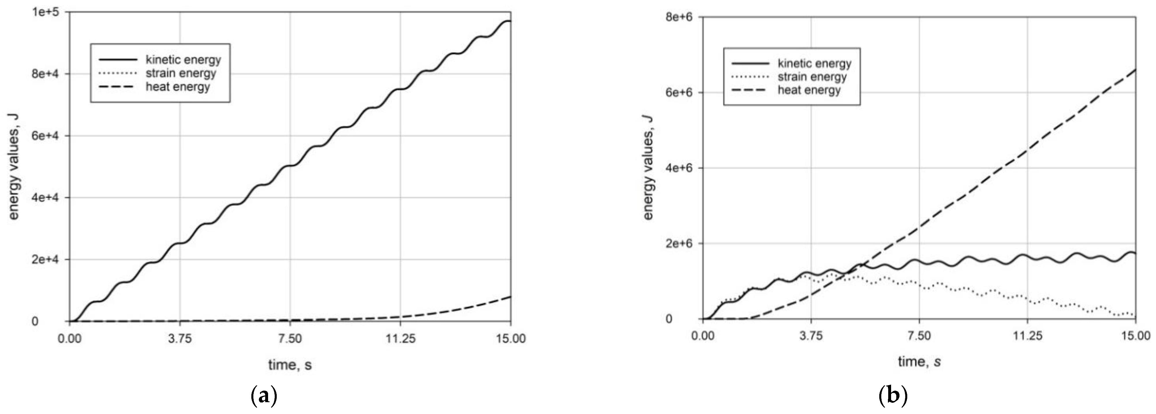
The plots for energy variations with time are shown in Figure 6. In these plots, the corresponding energy values are defined according to Equations (3g) and (3i).
Comparing these results reveals the following:
(A) Appearance of the substantial asymmetry in positive and negative strain pulses at the left end at large p 0 (Figure 5a) and almost symmetric pulses at small p 0 (Figure 4a); the explanation follows from the dependence of E on ε (Figure 2a) revealing that at small strain the function E ( ε ) is almost symmetric, while at large ε the corresponding tangent elastic modulus values become E ( 0.5 ) 1.8   MPa and E ( + 0.5 ) 1.51   MPa .
(B) When the distance from the left end increases, the strain magnitudes in both cases begins to decrease with forming shock wave fronts. In Figure 4b–d and Figure 5b–d, these shock wave fronts represent straight vertical lines between pulses of opposite signs. Another observation concerns the existence of multiple shock wave fronts; these fronts actually fill the whole region from the left end to the farthest point. A detailed analysis of the appearing shock wave fronts can be traced in Figure 7, where, according to Figure 2b, the faster moving parts associated with ε < 0.1 start to overtake the slower moving parts related to a large negative 0.2 < ε < 0.1 .
(C) In both cases p 0 = 50   KN and p 0 = 400   KN , strain energy starts to decrease in expense of an increase of thermal energy. At the same time, kinetic energy stabilizes, as plot 6b shows. Finally, the plots in Figure 6b reveal a substantial discrepancy between strain and kinetic energy, which appears when shock wave fronts begin to propagate and, hence, thermal energy is generated. Such a discrepancy is also observed at propagation of the dispersive surface acoustic waves, and acoustic waves in dissipative media.
The dimensionless distance ( l * ) from the left end of the rod that appeared in Figure 7, is defined as l * = l / L .

5. Concluding Remarks

The current analysis of propagating of the initially harmonic acoustic pulse of different amplitudes in a semi-infinite hyperelastic rod obeying Yeoh strain energy potential revealed a number of phenomena that have either not been observed previously, or have been attributed to a discontinuity in bi-modular media. The analysis is based on solving a nonlinear equation of motion by an explicit Lax–Wendroff time-difference scheme combined with the finite element discretization in the space domain.
The revealing phenomena include: (I) an observation of a decrease in the strain magnitudes with distance from the left end of the rod; such a decrease occurs for both large and small force excitation magnitudes, see Figure 4 and Figure 5. The considered phenomenon is caused by the formation and propagation of shock wave fronts. (II) It was also found that faster moving wave pulses, when overtaking slower moving pulses, lead to formation of shock wave fronts, see Figure 7. (III) The decrease in amplitude is associated with a simultaneous decrease in strain energy, and, as a consequence, an increase in thermal energy, see Figure 6. (IV) All the observed phenomena also occur at other frequencies in the studied range 10 1 f 10 2   Hz . The energy release at the shock wave formation and propagation is discussed in [74,75,76,77].
The observed results can have different applications, where rubber and other elastomeric rubberlike materials are used for manufacturing various bearing devices, especially for vibration and seismic protection. The current research discloses the nature of heat production observable even at small amplitudes of harmonic loads, which is due to the formation and propagation of shock wave fronts. Another application relates to the cloaking of distant regions from the initially harmonic pulses occurring at a broad frequency range.

Funding

This research was funded by the Ministry of Science and Higher Education RF, grant number FSWG-2023-0004.

Institutional Review Board Statement

Not applicable.

Informed Consent Statement

Not applicable.

Data Availability Statement

No data was used for the current research.

Conflicts of Interest

The author declares no conflict of interest.

References

  1. Rankine, W.J.M. On the thermodynamic theory of waves of finite longitudinal disturbances. Phil. Trans. Roy. Soc. London 1870, 160, 277–286. [Google Scholar]
  2. Vieille, P. Etude sur le role des discontinuites dans les phenomenes de propagation. Meml. Poudres Salpetres 1900, 10, 177–260. [Google Scholar] [CrossRef]
  3. Anile, A.M. Propagation of weak shock waves. Wave Motion 1984, 6, 571–578. [Google Scholar] [CrossRef]
  4. Courant, R.; Friedrichs, K.O. Supersonic Flow and Shock Waves; Interscience Inc.: New York, NY, USA, 1948. [Google Scholar]
  5. Landau, L.D. Shock waves at large distances from their place of formation. Sov. Phys. J. 1945, 9, 496–500. [Google Scholar]
  6. Lighthill, M.J. The diffraction of blast. I. Proc. Roy. Soc. Ser. A 1949, 198, 454–470. [Google Scholar]
  7. Maslov, V.P. Propagation of shock waves in an isentropic non-viscous gas. J. Math. Sci. 1980, 13, 119–163. [Google Scholar] [CrossRef]
  8. Maslov, V.P.; Mosolov, P.P. General theory of the solutions of the equations of motion of an elastic medium of different moduli. J. Appl. Math. Mech. 1985, 49, 322–336. [Google Scholar] [CrossRef]
  9. McCarthy, M.F. Singular surfaces and waves. In Continuum Physics; Eringen, A.C., Ed.; Academic Press: London, UK, 1975; Volume 2, pp. 449–521. [Google Scholar]
  10. Resler, E.L.; Lin, S.C.; Kantrowitz, A. The production of high temperatures in shock tubes. J. App. Phys. 1952, 23, 1390–1399. [Google Scholar] [CrossRef]
  11. Thomas, T.Y. The fundamental hydrodynamical equations and shock conditions for gases. Math. Mag. 1949, 22, 169–189. [Google Scholar] [CrossRef]
  12. Thomas, T.Y. The growth and decay of sonic discontinuities in ideal gases. J. Math. Mech. 1957, 6, 455–469. [Google Scholar] [CrossRef]
  13. Thomas, T.Y. Extended compatibility conditions for the study of surface discontinuity in continuum mechanics. J. Math. Mech. 1957, 6, 311–322. [Google Scholar]
  14. Whitham, G.B. On the propagation of shock waves through regions of non-uniform area or flow. J. Fluid Mech. 1958, 4, 337–360. [Google Scholar] [CrossRef]
  15. Whitham, G.B. A new approach to problems of shock dynamics. Part II. Three-dimensional problems. J. Fluid Mech. 1959, 5, 369–386. [Google Scholar] [CrossRef]
  16. Whitham, G.B. Linear and Nonlinear Waves; Wiley & Sons: New York, NY, USA, 1974. [Google Scholar]
  17. Toro, E.F. Riemann Solvers and Numerical Methods for Fluid Dynamics, 2nd ed.; Springer-Verlag: Berlin, Germany, 1999. [Google Scholar]
  18. Mortell, M.P.; Seymour, B.R. Nonlinearization and waves in bounded media: Old wine in a new bottle. J. Phys. Conf. Ser. 2017, 811, 012006. [Google Scholar] [CrossRef]
  19. Neumann, J.V.; Richtmyer, R. A method for the numerical calculation of hydrodynamic shocks. J. Appl. Phys. 1950, 21, 232–237. [Google Scholar] [CrossRef]
  20. Jordan, P.M.; Christov, C.I. A simple finite difference scheme for modeling the finite-time blow-up of acoustic acceleration waves. J. Sound Vibr. 2005, 281, 1207–1216. [Google Scholar] [CrossRef]
  21. Woodward, P.; Colella, P. The numerical simulation of two-dimensional fluid flow with strong shocks. J. Comp. Phys. 1984, 54, 115–173. [Google Scholar] [CrossRef]
  22. Yassein, S.M.; Ashwad, A.A. Efficient iterative method for solving Korteweg-de-Vries equations. Iraqi J. Sci. 2019, 60, 1575–1583. [Google Scholar] [CrossRef]
  23. Hartmann, R.; Houston, P. Adaptive discontinuous Galerkin finite element methods for the compressible Euler equations. J. Comp. Phys. 2002, 183, 508–532. [Google Scholar] [CrossRef]
  24. Menina, R.; Saurel, R. Modelling gas dynamics in 1D ducts with abrupt area change. Shock. Waves 2011, 21, 451–466. [Google Scholar] [CrossRef]
  25. Jin, H.; Wang, H.; Wu, Z.; Ge, Z.; Chen, Y. Numerical investigation of the effect of surface roughness on flow and heat transfer characteristics of single sphere particle in supercritical water. Comput. Math. Appl. 2019, 81, 562–572. [Google Scholar] [CrossRef]
  26. Lu, L.; Xu, J.; Ge, W.; Yue, Y. EMMS-based discrete particle method (EMMS–DPM) for simulation of gas–solid flows. Chem. Eng. Sci. 2014, 120, 67–87. [Google Scholar] [CrossRef]
  27. Zhou, L.; Lv, W.; Bai, L.; Han, Y.; Wang, J.; Shi, W.; Huang, G. CFD–DEM study of gas–solid flow characteristics in a fluidized bed with different diameter of coarse particles. Energy Rep. 2022, 8, 2376–2388. [Google Scholar] [CrossRef]
  28. Zel’dovich, Y.B.; Raizer, Y.P. Physics of Shock Waves and High-Temperature Hydrodynamic Phenomena; Dover Publications: New York, NY, USA, 2003. [Google Scholar]
  29. Karman, T.; Duwez, P. The propagation of plastic deformation in solids. J. Appl. Phys. 1950, 21, 987–994. [Google Scholar] [CrossRef] [Green Version]
  30. Howell, P.; Ockendon, H.; Ockendon, J.R. Mathematical modelling of elastoplasticity at high stress. Proc. R. Soc. A 2012, 468, 3842–3868. [Google Scholar] [CrossRef]
  31. Johnson, J.N.; Barker, L.M. Dislocation dynamics and steady plastic wave profiles in 6061 T6 aluminum. J. Appl. Phys. 1969, 40, 4321–4334. [Google Scholar] [CrossRef]
  32. Davison, L.; Graham, R. Shock compression of solids. Phys. Rep. 1979, 55, 255–379. [Google Scholar] [CrossRef]
  33. Cohen, T.; Durban, D. Longitudinal shock waves in solids: The piston shock analogue. Proc. R. Soc. A 2014, 470, 2164. [Google Scholar] [CrossRef] [Green Version]
  34. Grady, D.E. Shock-wave compression of brittle solids. Mech. Mater. 1998, 29, 181–203. [Google Scholar] [CrossRef]
  35. Graziani, F.; Moldabekov, Z.; Olson, B.; Bonitz, M. Shock physics in warm dense matter: A quantum hydrodynamics perspective. Contrib. Plasma Phys. 2021, 62, e202100170. [Google Scholar] [CrossRef]
  36. Molinari, A.; Ravichandran, G. Fundamental structure of steady plastic shock waves in metals. J. Appl. Phys. 2004, 95, 1718–1732. [Google Scholar] [CrossRef] [Green Version]
  37. Pack, D.C.; Evans, W.M.; James, H.J. The propagation of shock waves in steel and lead. Proc. Phys. Soc. 1948, 60, 1–8. [Google Scholar] [CrossRef]
  38. Taylor, G.I. The testing of materials at high rates of loading. J. Inst. Civ. Eng. 1946, 26, 486–519. [Google Scholar] [CrossRef]
  39. Hill, R. Acceleration waves in solids. J. Mech. Phys. Solids 1962, 10, 1–16. [Google Scholar] [CrossRef]
  40. Bland, D.R. On shock structure in a solid. J. Inst. Math. Appl. 1965, 1, 56–75. [Google Scholar] [CrossRef]
  41. Truesdell, C. General and exact theory of waves in finite elastic strain. Arch. Rat. Mech. Anal. 1961, 8, 263–296. [Google Scholar] [CrossRef]
  42. Truesdell, C.; Noll, W. The Non-Linear Field Theories of Mechanics; Springer: Berlin/Heidelberg, Germany, 2004. [Google Scholar]
  43. Dequiedt, J.L.; Stolz, C. Propagation of a shock discontinuity in an elasto-plastic material: Constitutive relations. Arch. Mech. 2004, 56, 391–410. [Google Scholar]
  44. Gavrilov, S.N.; Herman, G.C. Wave propagation in a semi-infinite heteromodular elastic bar subjected to a harmonic loading. J. Sound Vib. 2012, 331, 4464–4480. [Google Scholar] [CrossRef]
  45. Kuznetsova, M.; Khudyakov, M.; Sadovskii, V. Wave propagation in continuous bimodular media. Mech. Adv. Mater. Struct. 2021, 29, 3147–3162. [Google Scholar] [CrossRef]
  46. Lax, P.D.; Wendroff, B. Difference schemes for hyperbolic equations with high order of accuracy. Commun. Pure Appl. Math. 1964, 17, 381–398. [Google Scholar] [CrossRef]
  47. Lucchesi, M.; Pagni, A. Longitudinal oscillations of bimodular rods. Int. J. Struct. Stab. Dynam. 2005, 5, 37–54. [Google Scholar] [CrossRef]
  48. Ostrovsky, L.A. Wave processes in media with strong acoustic nonlinearity. J. Acoust. Soc. Am. 1991, 90, 3332–3337. [Google Scholar] [CrossRef]
  49. Radostin, A.; Nazarov, V.; Kiyashko, S. Propagation of nonlinear acoustic waves in bimodular media with linear dissipation. Wave Motion 2013, 50, 191–196. [Google Scholar] [CrossRef]
  50. Dudchenko, A.V.; Dias, D.; Kuznetsov, S.V. Vertical wave barriers for vibration reduction. Arch. Appl. Mech. 2021, 91, 257–276. [Google Scholar] [CrossRef]
  51. Zigoneanu, L.; Popa, B.I.; Cummer, S. Three-dimensional broadband omnidirectional acoustic ground cloak. Nat. Mater. 2014, 13, 352–355. [Google Scholar] [CrossRef] [Green Version]
  52. Rossikhin, Y.A.; Shitikova, M.V. A new method for solving dynamic problems of fractional derivative viscoelasticity. Int. J. Eng. Sci. 2001, 39, 149–176. [Google Scholar] [CrossRef]
  53. Shitikova, M.V.; Kandu, V.V.; Krusser, A.I. On nonlinear vibrations of an elastic plate on a fractional viscoelastic foundation in a viscoelastic medium in the presence of the one-to-one internal resonance. J. Sound Vibr. 2023, 549, 117564. [Google Scholar] [CrossRef]
  54. Yeoh, O.H. Some forms of the strain energy function for rubber. Rubber Chem. Tech. 1993, 66, 754–771. [Google Scholar] [CrossRef]
  55. Gajewski, M.; Szczerba, R.; Jemioło, S. Modelling of elastomeric bearings with application of Yeoh hyperelastic material model. Procedia Eng. 2015, 111, 220–227. [Google Scholar] [CrossRef] [Green Version]
  56. Knowles, J. Impact-induced tensile waves in a rubberlike material. J. Appl. Math. 2002, 62, 1153–1175. [Google Scholar] [CrossRef] [Green Version]
  57. Cardone, D.; Gesualdi, G. Experimental evaluation of the mechanical behaviour of elastomeric materials for seismic applications at different air temperatures. Int. J. Mech. Sci. 2012, 64, 127–143. [Google Scholar] [CrossRef]
  58. Reuter, T.; Ponomarev, I. Biomechanical parameter determination of scaffold-free cartilage constructs (SFCCs) with the hyperelastic material models Yeoh, Ogden and Demiray. Curr. Direc. Biomed. Eng. 2015, 1, 442–445. [Google Scholar] [CrossRef]
  59. Goldstein, R.V.; Dudchenko, A.V.; Kuznetsov, S.V. The modified Cam-Clay (MCC) model: Cyclic kinematic deviatoric loading. Arch. Appl. Mech. 2016, 86, 2021–2031. [Google Scholar] [CrossRef]
  60. Kuznetsov, S. Fundamental and singular solutions of Lame equations for media with arbitrary elastic anisotropy. Q. Appl. Math. 2005, 63, 455–467. [Google Scholar] [CrossRef] [Green Version]
  61. Kuznetsov, S. Lamb waves in stratified and functionally graded plates: Discrepancy, similarity, and convergence. Waves Random Complex Media 2019, 31, 1540–1549. [Google Scholar] [CrossRef]
  62. Kuznetsov, S. Abnormal dispersion of flexural Lamb waves in functionally graded plates. Z. Angew. Math. Phys. 2019, 70, 89. [Google Scholar] [CrossRef]
  63. Scovazzi, G.; Song, T.; Zeng, X. A velocity/stress mixed stabilized nodal finite element for elastodynamics: Analysis and computations with strongly and weakly enforced boundary conditions. Comp. Meth. Appl. Mech. Eng. 2017, 325, 532–576. [Google Scholar] [CrossRef]
  64. Winnicki, I.; Jasinski, J.; Pietrek, S. New approach to the Lax-Wendroff modified differential equation for linear and nonlinear advection. Numer. Meth. Part. Dif. Eq. 2019, 35, 2275–2304. [Google Scholar] [CrossRef] [Green Version]
  65. Simon Portillo, F.J.; Cuadrado Sempere, Ó.; Marques, E.A.; Sánchez Lozano, M.; Da Silva, L.F. Mechanical characterisation and comparison of hyperelastic adhesives: Modelling and experimental validation. J. Appl. Comput. Mech. 2022, 8, 359–369. [Google Scholar]
  66. Pence, T.J.; Gou, K. On compressible versions of the incompressible neo-Hookean material. Math. Mech. Solids 2015, 20, 157–182. [Google Scholar] [CrossRef]
  67. Ilyashenko, A.V.; Kuznetsov, S. Theoretical aspects of applying Lamb waves in nondestructive testing of anisotropic media. Russ. J. Nondestruct. Test. 2017, 53, 243–259. [Google Scholar] [CrossRef]
  68. Ilyashenko, A.V.; Kuznetsov, S.V. Pochhammer–Chree waves: Polarization of the axially symmetric modes. Arch. Appl. Mech. 2018, 88, 1385–1394. [Google Scholar] [CrossRef]
  69. Zemanek, J. An experimental and theoretical investigation of elastic wave propagation in a cylinder. J. Acoust. Soc. Am. 1972, 51, 265–283. [Google Scholar] [CrossRef]
  70. Gurtin, M.E.; Williams, W.O. On the first law of thermodynamics. Arch. Ration. Mech. Anal. 1971, 42, 77–92. [Google Scholar] [CrossRef] [Green Version]
  71. Zohuri, B.; McDaniel, P. First law of thermodynamics. In Thermodynamics In Nuclear Power Plant Systems; Springer: Berlin, Germany, 2015. [Google Scholar]
  72. Djeran-Maigre, I.; Kuznetsov, S.V. Velocities, dispersion, and energy of SH-waves in anisotropic laminated plates. Acoust. Phys. 2014, 60, 200–207. [Google Scholar] [CrossRef]
  73. Burtscher, S.L.; Dorfmann, A. Compression and shear tests of anisotropic high damping rubber bearings. Eng. Struct. 2004, 26, 1979–1991. [Google Scholar] [CrossRef]
  74. Davison, L. Fundamentals of Shock Wave Propagation in Solids; Springer: Berlin, Germany, 2008. [Google Scholar]
  75. Goldstein, R.V.; Kuznetsov, S.V. Long-wave asymptotics of Lamb waves. Mech. Solids 2017, 52, 700–707. [Google Scholar] [CrossRef]
  76. Li, S.; Brun, M.; Djeran-Maigre, I.; Kuznetsov, S. Hybrid asynchronous absorbing layers based on Kosloff damping for seismic wave propagation in unbounded domains. Comp. Geotech. 2019, 109, 69–81. [Google Scholar] [CrossRef]
  77. Zubeldia, M. Energy concentration and explicit Sommerfeld radiation condition for the electromagnetic Helmholtz equation. J. Func. Anal. 2012, 263, 2832–2862. [Google Scholar] [CrossRef] [Green Version]
Figure 1. (a) Semi-infinite rod. (b) Harmonic load, applied at the left end.
Applsci 13 04740 g001
Figure 2. (a) Tangent elastic modulus variation vs. strain. (b) Rod velocity variation vs. strain.
Applsci 13 04740 g002
Figure 3. 1D rod of length L with points of observation marked as x0, …, x3.
Applsci 13 04740 g003
Figure 4. Nominal strain variation vs. time at points of observation: (a) x0; (b) x1; (c) x2; (d) x3; at p0 = 50 KN and f = 1 Hz.
Applsci 13 04740 g004
Figure 5. Nominal strain at points of observation: (a) x0; (b) x1; (c) x2; (d) x3; at p0 = 400 KN and f = 1 Hz.
Applsci 13 04740 g005
Figure 6. Energy variation vs. time, frequency f = 1 Hz; (a) p0 = 50 KN; (b) p0 = 400 KN.
Applsci 13 04740 g006
Figure 7. Formation of shock wave fronts at points of observation near the left end of the rod for p0 = 400 KN and f = 1 Hz.
Applsci 13 04740 g007
Disclaimer/Publisher’s Note: The statements, opinions and data contained in all publications are solely those of the individual author(s) and contributor(s) and not of MDPI and/or the editor(s). MDPI and/or the editor(s) disclaim responsibility for any injury to people or property resulting from any ideas, methods, instructions or products referred to in the content.