Abstract
To address the issue of tension fluctuations and deviations among the strands during cable-twisting production, it is necessary to establish a relationship model between the centrifugal force, frictional force, and tension experienced by each strand in a single span range under the state of traveling and rotating. Considering the differences of strand alignment at the distribution reel, the effects of centrifugal force and friction on strand tension under different twisting-deflection paths and cylinder-traveling paths should be analyzed. In our study, different stress states of each strand were applied to simulate and verify the tension fluctuations and deviations of every strand under various traveling and deflection paths. The experimental results show that the increasing travel path of the strand cylinder will cause an increase in the average strand tension. Different deflection paths in the distribution reel will affect the range of the strand tension fluctuation. A sliding mode controller based on a discrete system was designed in MATLAB to control the tension fluctuation and deviation among the strands. The results indicated that this control method can effectively reduce the tension deviation between strands, and the average tension fluctuation range of each strand was reduced by 79.5%.
1. Introduction
The equilibrium of tension between strands in cable twisting is of great significance to the improvement of the mechanical properties of cables [1,2]. The cable-twisting production scheme is shown in Figure 1. The model of the cable-twisting equipment was established in the solidworks. During the stranding process, the tension of each strand may deviate due to different twisting conditions, and the strands may be squeezed out during twisting, resulting in broken or disordered strands. This may further lead to quality issues in the product and may result in more severe safety incidents, such as a cable-bearing fracture [3,4].
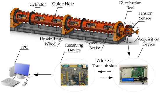
Figure 1.
Strand-twisting production schematic diagram.
The early research work on cable-system mechanics mainly focused on the vibration mechanics analysis of the cable system and the mechanical performance analysis of the geometric structure [5,6]. Wu et al. [7] established a multidirectional coupling vibration model of the cable strand. They used the Galerkin truncation method to solve the model parameters and verified the strand dynamics model based on the experimental system. Ding et al. [8] established a dynamic model of the single-rope winding lifting system based on the Hamilton principle to obtain the relationship between the tension deviation between two cables and the longitudinal vibration. Qian et al. [9] introduced a displacement interpolation function based on the absolute node co-ordinate method to establish the structural deformation model of the strand under the axial load. Tang et al. [10] established a spiral line equation with the periodic boundary condition based on the spatial analytical geometry method to obtain the relationship between the bending, torsion force, and tension of the strand. Domestic and foreign researchers have also performed relevant work on the tension deviation between strands or cables. Zang et al. [11] combined the traditional and coupled disturbance observer through estimating the Coulomb friction and compensating for the coupled disturbance; they used a nonlinear inverse step control scheme to reduce the tension deviation of two cables in the lifting system. Ding et al. [12] established a distributed dynamic model and designed a parameter-adaptive strand-tension-balance robust boundary controller to achieve cable-tension-balance control and longitudinal vibration suppression of the lifting container. Chen et al. [13] analyzed the redundancy characteristics of each actuator to reduce the tension deviation of each strand under the impact, and proposed a hybrid control scheme based on iterative learning control and a radial basis function neural network to improve the performance of the controller. Li et al. [14] combined a low-gain state observer and a nonlinear robust adaptive controller to address the cable tension imbalance problem in the double-rope winding lifting system, and verified that the algorithm has a superior performance in strand tension equilibrium control.
However, there has been limited research on the analysis of the forces on each strand and the control of the tension deviation under the twisting working condition of the cable. We explored the causes of the tension deviation of strands under different twisting working conditions, and analyzed the forces of strands at the guide hole of the cylinder and the twisting deflection of the distribution reel. The tension data of strands under different traveling paths and twisting-deflection paths were obtained through simulation experiments in the laboratory. A discrete sliding mode control method was used to respond in real time to dynamic changes in the strand tension, and reduced the influence of the above interference factors on the strand tension. Tension equilibrium and fluctuation reduction were ultimately achieved between the strands by adjusting the control parameters.
2. Analysis of Forces Acting on Strands during Traveling
During the working process of the cable-twisting equipment, the strands move along the guide holes between the cylinders at a constant speed while the cylinder is moving at a constant speed in a circular motion. The strands must pass through several spans of continuous traction from the unwinding end to the closing end. In order to clearly analyze the tension of the strand during its movement, it is necessary to carry out a force analysis of the strand at the guide hole and under different deflection paths on the distribution reel during the entire twisting process.
2.1. Analysis of Forces on Guide Holes
The movement of the strand between the cylinder bodies is a complex and multi-span composite motion, making it difficult to model and analyze the strand over the entire span range. At the same time, different strands follow different paths during the twisting process, and they pass through a different number of guide holes. Therefore, it is a prerequisite and basic for the strand in the overall feeding process to analyze the force between the strand and guide hole under a single span. The arrow of w stands for center axis rotation, as shown in Figure 2. The figure was drawn in the visio.
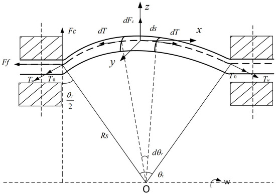
Figure 2.
Analysis of the force on strands and guide holes under single span.
When the strand rotates radially along the cylinder, it is subject to an outward movement tendency and is compressed against the inner wall of the guide hole under the action of centrifugal force . By dividing the wire strand into small elements, the force analysis can be carried out as follows:
where is the radius of rotation, is the length of the strand element, is the tension of the strand element, and is the centrifugal force. The magnitude of satisfies the following relationship:
where is the linear density of the strand element, and is the rotational angular velocity. Combining (1) and (2) together:
Expanding using the Taylor series and omitting higher-order terms yields:
Combining Equations (3) and (4), dT can be integrated and simplified within the single-span range:
The strand travels through multiple guide holes and spans, and the motion of the strand in each span is assumed to be superimposed on the next one [15]. The initial tension of the strand at the Jth span can be obtained:
where is the pre-tensioning force applied to the strand by the hysteresis brake at the unwinding end. Under the action of centrifugal force, the strand element in a single span presents a certain curvature, but its degree of bending can be neglected compared to the rotation radius , approximately as a straight line. The centrifugal force is uniformly distributed within a single span. The friction force between the strand and the guide hole can be calculated according to the following formula:
where is the sliding friction factor between the strand and the guide hole, and m is the strand mass within the full span.
2.2. Analysis of Force under Different Strand Paths on the Distribution Reel
In the twisting process, the strands are twisted from the cylinder to the distribution reel, and each strand changes from a triangular distribution to a circumferentially uniform distribution. Each strand shows a different twisting-deviation path at the distribution reel, as shown in Figure 3. represents the angle of rotation corresponding to different deflection paths of strands with different numbers at the distribution reel, . The angle is the angle between each strand and surface .
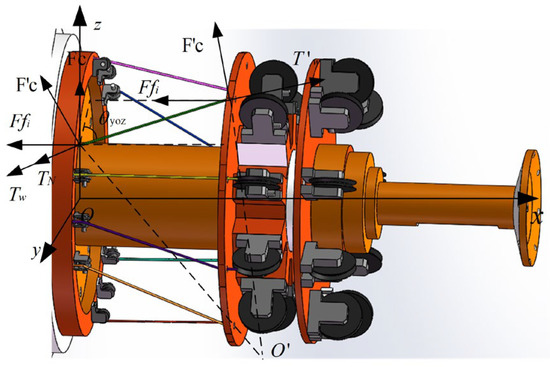
Figure 3.
Force analysis of different twisting-deflection angles on the distribution reel.
The vector radius of any point A on the strand can be expressed as (8):
where dx, dy, and dz are the three co-ordinates of any point A on the strand, and i, j, and k are the base vectors of the co-ordinate axis. The cosines of the three directions of the tangent vector with respect to the space co-ordinate axis system are ,,. The length from the strand to the point A where it is led out of the cylinder is denoted as S. The deviation angle at any point A can be expressed as:
Due to the different paths of each strand on the distribution reel, the length of strand S varies. When different strands undergo a rotational motion along the central axis, the equivalent torsion radius is related to the twisting-deflection angle as follows:
where i represents the corresponding number of the twisted strand, and and correspond to the twisting-deflection angle and the length of the twisted strand with different numbers, respectively.
We then combine Equations (10) with (5). This can be integrated and simplified within the range of the span to obtain:
Under the condition of the rotating twisting and traveling, the inner wall of the guide hole will exert a certain hindering force on the strand, which can be expressed as:
3. Analysis of Tension Influencing Factors during Strand Movement
3.1. Analysis of Travelling Path Deviation at the Cylinder
The model of the twisting machine’s cylinder was established to analyze the influence of different guide-hole spans on the tension of each strand. The number of guide holes passed by each strand under different strand numbers was recorded as Ni. From Equation (5), it can be seen that the tension of the strand has a certain mathematical relationship with the rotation speed within a single span. Therefore, the tension of each strand within a single span under different speeds is calculated.
Figure 4 shows the tension deviation of each strand with different rotational speeds. There is a positive correlation coupling relationship between the tension deviation of the strand with the rotational speed and the number of guide holes. The more guide holes the strand goes through, the greater the deviation between the initial tension and the output tension at the end of the cylinder. The tension deviation of a strand is small with a low speed. As the rotational speed increases, the influence of the rotational speed on the tension deviation of each strand increases significantly. With a lower number of guide holes the strand passes through, the rotational speed has a smaller impact on the tension of the strand.
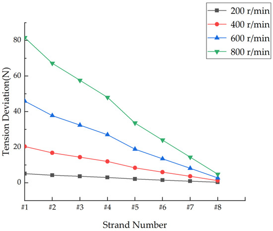
Figure 4.
Tension deviation of each strand at different rotational speeds.
3.2. Analysis of Different Twisting Paths of Strands at the Distribution Reel
The differences in twisting-deviation paths are due to the asymmetric distribution of the guide holes at the exit of the cylinder and at the distribution reel. They lead to significant differences in the twisting angle between the strands, as shown in Figure 5. In order to simulate the actual deflection path of each strand in the twisting process, the projected lengths of each strand on the x, y, and z axes at the distribution reel are measured and denoted as , , and , respectively. represents the actual length of the strand. The angles between each strand and the co-ordinate plane for the x, y, and z axis are calculated, and recorded as , , and . The measured data can be found in Table 1.
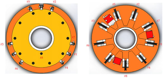
Figure 5.
Position relation of each strand in y–z direction of the distribution reel.

Table 1.
The spatial relative position of each strand and the length in the co-ordinate system.
Different deviation paths result in different levels of interference force on each strand at the bending point on the distribution reel. Numerical calculation and analysis are performed to investigate the force distribution of each strand at the exit point of the cylinder. Through Equations (10), (11), and (14), the equivalent torsional radius and friction force for different strands are calculated, and the tension value of each strand is recorded in Table 2, where the tension is composed of the tension deviation under the corresponding travelling path of each strand, the tension produced by different deflection angles of the distribution reel, and the initial braking tension .

Table 2.
Values of radius of gyration, tension, and frictional force for each strand at different speeds.
Table 2 records the effects on the tension of each strand with different twisting-deviation paths , cylinder-travelling paths , and speeds . It can be seen that for the #2, #4, and #5 strands, the influence of the guide-hole friction is relatively small. This is because these three strands are parallel to each other relative to the rotation center axis when they are drawn out from the cylinder. There is no obvious squeezing phenomenon between the strands and guide holes. The frictional force that the strands are subjected to is due to the centrifugal force caused by the rotation of the cylinder. The rotation of the cylinder makes the strands come into contact with the guide holes. The mass of the strands is small, so the frictional force generated by the centrifugal force is also small.
4. Experimental Analysis
Each strand goes through different paths of the cylinder to the distribution reel. There are different tension, friction, and centrifugal forces of each strand with different twisting paths. A theoretical analysis and calculation were conducted to determine the tension of each strand over the full span range. The relationship between the tension of each strand and the factors including twisting paths, friction, and centrifugal forces were experimentally obtained according to the theoretical values.
4.1. Experimental Setup Construction
The experimental setup mainly consists of the unwinding wheel, winding wheel, braking system, guide rail sliding block mechanism, sliding friction platform, PLC, tension sensor, and upper computer as shown in Figure 6. The braking system is used to provide the strand tension at the end of the cylinder, and the sliding friction platform applies friction force to the strand. The guide rail sliding block is used to change the direction of the centrifugal force on the strand during the twisting process. The tension sensor senses the change of the strand tension in real time through the PLC, and the PLC-Recorder converts and stores the strand tension data in real time.
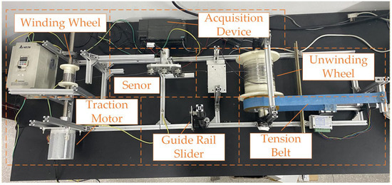
Figure 6.
Simulation and experimental apparatus for strand movement.
To simulate different twisting paths of each strand at the distribution reel, the relative position between the winding wheel and the sensor was changed in the experimental setup. As shown in Figure 7, a three-dimensional co-ordinate system was established at tension sensor, and the distance between the wheel and the sensor was changed. Simulated experiments were carried out for each of the eight strands at speeds of 200 r/min and 300 r/min. The initial brake tension was set to 2 N, and the initial test conditions are shown in Table 3.
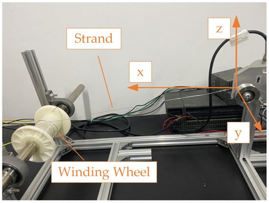
Figure 7.
The relative position relationship between the winding wheel and the sensor.

Table 3.
Analysis of the initial state of each strand under different speeds.
4.2. Data Analysis and Discussion
When the simulated forces were applied to each strand, the strand tensions showed a certain fluctuation, as shown in Figure 8. The colored lines represent strands with different numbers, corresponding to strand number axes in the figure. When the rotational speed was the same and the strand did not have an obvious deflection at the distribution reel (#2, #4, and #5), the tension of the strand closer to the twisting end was small, and the strand farther away from the twisting end was larger. The average strand tension was positively correlated with the span of the guide holes. The more guide holes the strand passed through, the larger the average tension.
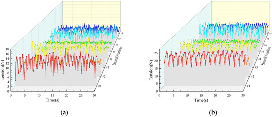
Figure 8.
(a) 200 r/min tension data of each strand; and (b) 300 r/min tension data of each strand.
The range of tension fluctuation of each strand at 200 r/min and 300 r/min is presented in box plots in Figure 9. As the speed increased, the range of the tension fluctuation and the average tension of each strand increased. For the same speed, when the strand had a significant deviation at the distribution reel, the average tension increased, indicating an increase in the overall force on the strand. When the deviation of the strand at the distribution reel was small, the range of the tension fluctuation obviously decreased. It is evident that the change of the strand twisting-deviation path affects the range of the tension fluctuation.
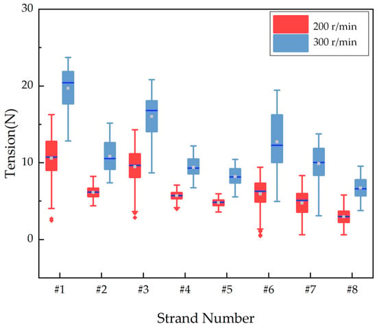
Figure 9.
Box diagram of strand tension at different speeds.
It can be seen that there is a certain deviation in the tension between each strand based on the analysis and experiments of the various influencing factors. According to the input and output data of the system, a strand-tension system model was established based on the systematic identification theory, and the discrete form of the system model can be represented by Equation (13).
For the #1, #3, #6, and #8 strands, the tension fluctuation and deviation between different strands were more obvious. Therefore, the system model for these strands at 300 r/min can be established as shown in Table 4.

Table 4.
Models of tension control systems for each strand.
5. Control Strategy for Strand Tension Equilibrium
In the twisting process, the interference caused by the travelling path of the cylinder and the twisting path of the distribution reel results in differences in wire tension. The balance of strand tension directly affects the quality of cable twisting. Traditional PID control is not suitable for tension control in cable twisting because of its large overshoot, lagging response, and poor anti-interference ability. Therefore, a sliding mode controller based on a discrete-time system is designed to reduce the tension fluctuation and deviation between strands [16,17,18]. Sliding mode control is a control strategy characterized by control discontinuity. The differences between sliding mode control and other controls are that the structures of the system are not fixed and can dynamically change according to the current state of the system. For cable-twisting equipment, each strand is subjected to different cylinder-travelling and twisting-deflection paths, which have an impact on the fluctuation and deviation of strand tension. Sliding mode control can greatly reduce these disturbances, enabling the system to follow the sliding mode surface to achieve the better tracking of a given signal.
5.1. The Design of The Discrete Sliding Mode Controller
The design process of the sliding mode controller is shown in Figure 10 [19,20]. Based on the system models of each numbered strand, the state space equations are constructed, which are represented by Equation (14):
where A, B, C, and D correspond to the state matrix, input matrix, output matrix, and direct action matrix of the system, respectively, with representing the initial state of the state space equation, representing the current output of the system, and representing the system control variable. The design of the discrete sliding mode surface is:

Figure 10.
Design of discrete sliding mode controller.
represents the coefficients of the designed sliding surface. Based on the discrete index convergence rate, the sliding mode controller is designed as in Equation (18):
where T is the system sampling time, , , and . The discrete sliding mode control law based on the exponential convergence rate can be obtained as follows:
where sat (s) is the saturation function.
5.2. Simulation Analysis of Strand Tension Equilibrium
A discrete sliding mode controller is designed for cable-twisting equipment to reduce the tension fluctuation and deviation caused by the different paths of the cylinder travelling and twisting deviation, , T = 0.2 s, , and . Based on the state space equations of each strand, the sliding surface coefficients for #1, #3, #6, and #8 were set to [1, 2, 1], [1.4, 2.5, 1.15], [1.5, 2.5, 1], and [0.4, 1.1, 1.3], respectively. The simulation results of each strand which was processed by discrete sliding mode control were obtained, as shown in Figure 11. The simulation results showed that the tension fluctuation of different numbered strands was significantly reduced, and the mean tension of each strand tended to the target set value (set value = 10 N).
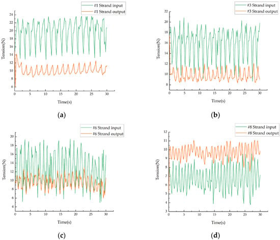
Figure 11.
Comparison of tension of each strand before and after tension control: (a) comparison of #1 strand tension; (b) comparison of #3 strand tension; (c) comparison of #6 strand tension; and (d) comparison of #8 strand tension.
As shown in Figure 12, under the sliding mode control based on the discrete system, the tension fluctuations of the different strands are significantly reduced, by 85.2%, 84.2%, 86.1%, and 62.6%, respectively. The average tension of each strand is reduced by 19.7 N, 16.1 N, 12.7 N, and 6.7 N, to 10.2 N, 9.8 N, 9.6 N, and 9.7 N; thus, the tension deviation between the strands is significantly reduced. In the cable-twisting equipment, the sliding mode controller designed based on the discrete system can reduce the interference of different friction forces and centrifugal forces on the tension of each strand effectively. At the same time, for the problem of the large tension deviation between the strands due to the different traveling paths and twisting-deflection paths, the designed controller can reduce the deviation between the strands effectively. This is of great significance for the equilibrium control of the tension of each strand in the cable-twisting equipment.
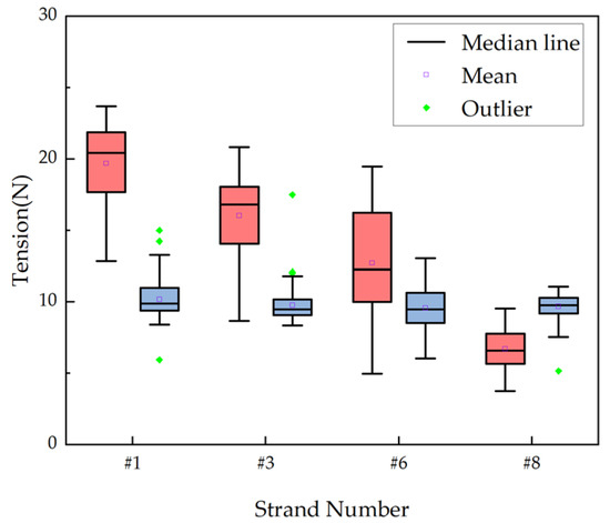
Figure 12.
Box plot comparing tension of each strand before and after control intervention.
6. Conclusions
Multi-strand tension equilibrium is of great significance to improving the quality of the cable. The force of each strand in the twisting process of wire ropes produced by the cable-twisting equipment is analyzed based on the different paths of the cylinder travelling and twisting deflection. A model is established for the relationship between the tension, friction, and centrifugal force of each strand. This paper provided a new modeling idea for the force analysis of strands under twisting conditions, and the influence of different interference factors on the tension fluctuation and deviation of each strand is analyzed and verified through simulation experiments. A reasonable explanation can be given for the phenomenon of fluctuations and deviations in the tension of each strand during the production of cable-twisting equipment. A sliding mode controller based on discrete time systems is designed to reduce the tension fluctuation of each strand in the cable-twisting equipment and achieve a balanced control of the tension equilibrated. By analyzing the factors affecting the strand tension and designing the controller, it is of great significance to the study and application of the causes and controlled methods of strand-tension fluctuation and deviation in existing cable-twisting equipment.
Author Contributions
Writing—original draft, X.C.; Writing—review & editing, W.Y. All authors have read and agreed to the published version of the manuscript.
Funding
This research was funded by the key research and development program in Zhejiang Province of China (Grant No. 2022C01209 and 2023C010632) and the key research and development program in Hangzhou of China (Grant No. 2022AIZD0023).
Institutional Review Board Statement
Not applicable.
Informed Consent Statement
Not applicable.
Data Availability Statement
Not applicable.
Acknowledgments
This research was supported by the Ningbo Kaite Machinery Co., Ltd.
Conflicts of Interest
The authors declare no conflict of interest.
References
- Guo, Y.; Zhang, D.; Zhang, X.; Wang, D.; Wang, S. A New Transmission Theory of “Global Dynamic Wrap Angle” for Friction Hoist Combining Suspended and Wrapped Wire Rope. Appl. Sci. 2020, 10, 1305. [Google Scholar] [CrossRef]
- Debeleac, C.; Nastac, S.; Musca, G.D. Experimental Investigations Regarding the Structural Damage Monitoring of Strands Wire Rope within Mechanical Systems. Materials 2020, 13, 3439. [Google Scholar] [CrossRef] [PubMed]
- Mező, T.B.; Barkóczy, P. Impact of Strain Aging Kinetics on the Failure of Thin Steel Wire Ropes. In Proceedings of the 1st International Electronic Conference on Metallurgy and Metals (IEC2M 2021), Online, 22 Feburary–7 March 2021. [Google Scholar] [CrossRef]
- Chen, X.; Zhu, Z.; Ma, T.; Chang, J.; Chang, X.; Zang, W. An Adaptive Dynamic Surface Technology-Based Electromechanical Actuator Fault-Tolerant Scheme for Blair Mine Hoist Wire Rope Tension Control System. Actuators 2022, 11, 299. [Google Scholar] [CrossRef]
- Wang, L.; Cao, G.; Wang, N.; Yan, L. Modeling and Dynamic Behavior Analysis of Rope-Guided Traction System with Terminal Tension Acting on Compensating Rope. Shock. Vib. 2019, 2019, 6362198. [Google Scholar] [CrossRef]
- Wang, X.-Y.; Meng, X.-B.; Wang, J.-X.; Sun, Y.-H.; Gao, K. Mathematical modeling and geometric analysis for wire rope strands. Appl. Math. Model. 2015, 39, 1019–1032. [Google Scholar] [CrossRef]
- Wu, G.; Xiao, X.; Yao, J.; Song, C. Machine vision–based measurement approach for transverse vibrations of moving hoisting vertical ropes in mine hoists using edge location. Meas. Control 2019, 52, 554–566. [Google Scholar] [CrossRef]
- Ding, X.; Shen, G.; Li, X.; Tang, Y. Delay compensation position tracking control of electro-hydraulic servo systems based on a delay observer. Inst. Mech. Eng. 2020, 234, 622–633. [Google Scholar] [CrossRef]
- Qian, Y.; Wang, H.; Yu, H. Dynamic Model and Characteristics of Steel Cable Structures Based on the Absolute Nodal Coordinate Method. Chin. Mech. Eng. 2018, 29, 1540–1546. [Google Scholar] [CrossRef]
- Tang, Y.; He, X.; Li, Y.; Zhang, R.; Hu, Z. Stress Analysis of Wire Strands by Mesoscale Mechanics. J. Ocean Univ. China 2022, 21, 1118–1132. [Google Scholar] [CrossRef]
- Zang, W.; Chen, X.; Zhao, J. Multi-Disturbance Observers-Based Nonlinear Control Scheme for Wire Rope Tension Control of Hoisting Systems with Backstepping. Actuators 2022, 11, 321. [Google Scholar] [CrossRef]
- Ding, X.; Shen, G.; Tang, Y.; Li, X. Axial vibration suppression of wire-ropes and container in double-rope mining hoists with adaptive robust boundary control. Mechatronics 2022, 85, 102817. [Google Scholar] [CrossRef]
- Chen, X.; Zhu, Z.; Shen, G.; Li, W. Tension coordination control of double-rope winding hoisting system using hybrid learning control scheme. Proc. Inst. Mech. Eng. Part I J. Syst. Control. Eng. 2019, 233, 1265–1281. [Google Scholar] [CrossRef]
- Li, X.; Zhu, Z.; Cheng, D.; Shen, G.; Tang, Y. A Robust Nonlinear Controller With Low-Gain-State-Observer for Wire Rope Tension Active Control of Hoisting Systems. IEEE Access 2020, 8, 111208–111222. [Google Scholar] [CrossRef]
- Sun, Y.; Yu, Y.; Shan, J.; Bao, G.; Yin, X. Multi-strand tension balance with self-adaptive control in twisting equipment. Comput. Integr. Manuf. Syst. 2021, 27, 3559–3568. [Google Scholar] [CrossRef]
- Shao, J.; Bian, Y.; Yang, M.; Liu, G. High Precision Adaptive Fuzzy Control Method for Hydraulic Robot Joint. In Proceedings of the 2022 IEEE 13th International Conference on Mechanical and Intelligent Manufacturing Technologies (ICMIMT), Cape Town, South Africa, 25–27 May 2022; pp. 285–290. [Google Scholar] [CrossRef]
- Ma, F.; Lian, L.; Ji, P.; Yin, Y.; Chen, W. Fault Diagnosis Scheme Based on Microbial Fuel Cell Model. IEEE Access 2020, 8, 224306–224317. [Google Scholar] [CrossRef]
- Zhao, W.; Ren, X.; Gao, X. Synchronization and tracking control for multi-motor driving servo systems with backlash and friction. Int. J. Robust Nonlinear Control. 2016, 26, 2745–2766. [Google Scholar] [CrossRef]
- Song, C.; Fei, S.; Cao, J.; Huang, C. Robust Synchronization of Fractional-Order Uncertain Chaotic Systems Based on Output Feedback Sliding Mode Control. Mathematics 2019, 7, 599. [Google Scholar] [CrossRef]
- Wang, X.; Zhang, Y.; Gao, P. Design and Analysis of Second-Order Sliding Mode Controller for Active Magnetic Bearing. Energies 2020, 13, 5965. [Google Scholar] [CrossRef]
Disclaimer/Publisher’s Note: The statements, opinions and data contained in all publications are solely those of the individual author(s) and contributor(s) and not of MDPI and/or the editor(s). MDPI and/or the editor(s) disclaim responsibility for any injury to people or property resulting from any ideas, methods, instructions or products referred to in the content. |
© 2023 by the authors. Licensee MDPI, Basel, Switzerland. This article is an open access article distributed under the terms and conditions of the Creative Commons Attribution (CC BY) license (https://creativecommons.org/licenses/by/4.0/).