Abstract
Buckling-restrained braces (BRBs) have been widely employed in buildings and bridges due to their excellent ductility and energy dissipation capabilities. However, a considerable frame action will be introduced at the beam–column–brace joint for the traditional weld gusset connection under a severe earthquake. To reduce the negative frame action effect, three alternative bolted gusset connections were developed in this study. A buckling-restrained braced-double-pier RC bridge (BRB-RCB) model was constructed by ABAQUS and calibrated by the existing experimental tests. Parameter analyses were conducted to investigate the effects of various connection types on the seismic performance of the BRB-RCBs. It was found that the proposed bolted gusset connection effectively released the constraints of gusset-to-frame interfaces, resulting in a low stress level at the panel zone. The BRB-RCB with the well-designed bolted connection exhibited excellent seismic performance even when subjected to a lateral drift of 3%.
1. Introduction
A buckling-restrained brace (BRB) is a type of bracing component combining the functions of an ordinary brace and a metal damper [1,2,3,4]. With the lateral constraint provided by the external restrainers, the steel core of BRBs can afford sufficient lateral stiffness to the main structure under a frequent earthquake and dissipate the seismic energy through their elasto-plastic deformation under a medium or severe earthquake. BRBs have been widely used in engineering applications for these advantages.
Numerous studies have shown that BRBs can be used as energy dissipation fuses for the structures, in that BRBs can yield and dissipate the seismic energy prior to the main structure under seismic activity [5,6,7]. El-Bahey et al. [8] adopted BRBs to retrofit non-ductile reinforced concrete (RC) bridge bents. The nonlinear analysis results indicated that BRBs effectively improve the seismic performance of the existing RC bridge bents. Upadhyay et al. [9] also proposed the accurate numerical models for the BRB and SCBRB, which can reproduce hysteretic responses, including cyclic strain hardening and fatigue failure of braces. Xiang et al. [10] compared the relative effectiveness of different dampers by seismically retrofitting an RC double-pier bent under near-fault and far-field ground motions, in which the BRB-retrofitted bent had the higher effectiveness in reducing the bent damage under the far-field ground motions than the latter. To fully utilize the energy dissipation capacity of BRBs by retrofitting the bridge bents, a toggle BRB system, combining the functions of the structural fuse and toggle brace mechanism, was proposed by Shi et al. [11]. Compared with the diagonal BRB system, the toggle BRB system exhibited a higher effectiveness of energy dissipation and a lower displacement demand. Furthermore, Shi et al. [12] proposed the multistage BRBs with different yield strengths to meet the stiffness requirement of the retrofitted bend after the brace yields. The diagonal multistage BRB system had a satisfactory energy dissipation capacity, and the seismic performance of RC bents can be improved with the increasing post-yield stiffness ratio of the steel core. However, some researchers have found that the premature failure of the panel zone can be caused by the opening and closing behavior of the beam–column joint under a severe earthquake [13,14,15,16]. To improve the seismic performance of buckling-restrained braced steel frames (BRBFs), Fahnestock et al. [17] proposed a beam–column–brace connection, in which the pin was introduced at the brace–gusset connection, in addition to the bolted beam splice being employed between the beam stub and beam. Thus, the negative effects of frame action can be successfully prevented. With the aim of reducing the undesired rigid gusset zone effect, two innovative beam–gusset–column connections without bending movement transferred for BRBFs were proposed by Fatemi et al. [18], in which the gusset-to-column connection adopted slidable bolts. The finite element results verified that the BRBFs with the well-designed connections had satisfactory hysteretic responses without suffering low-cycle fatigue.
As for the buckling-restrained braced reinforced concrete structures, the corresponding panel zone has the more complex configuration and working mechanism. Figure 1 demonstrates three traditional gusset-to-frame connection configurations. Obviously, the first two connections cannot reduce the frame action effect due to their rigid connections. In spite of the opening and closing behavior of the gusset connection being diminished using the third method, the additional strong shear interaction at the beam end might induce the premature shear failure of the concrete beam or buckling failure of the BRB. Large-scale self-centering buckling-restrained braced reinforced concrete double-column bridge piers with an anchorage plate connection was experimentally and numerically investigated by Dong et al. [19,20]. The research results demonstrated that the plastic damage concentrated around the top of the column near the built-in gusset tip was the reason for the sudden change in lateral stiffness along the column, due to the existence of the built-in anchorage connection. Bazaez et al. [21] conducted the large scale quasi-static cyclic experiments of BRB-RCBs using an unconstrained gusset connection, and there was no significant cracking and no cracking of the plastic hinge observed during the testuntil the ductility of the retrofitted structure achieving 8. Based on these large-scale hysteretic experiments of RC bridge bents retrofitted with a BRB, Bazaez et al. [22] established the refined finite element models, which can satisfy the precise requirements at the system- and component-level. Zhao et al. [23] proposed two innovative sliding gusset connections to mitigate the unintended frame action effect, which utilized the sliding mechanism at the gusset-to-frame interfaces. Subassemblage tests revealed that the force transfer path at the gusset-to-frame interface can be shifted by adopting the suggested connections, resulting in a lower shear force and energy dissipation demands on the RC frames.
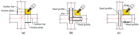
Figure 1.
Traditional gusset connection configurations: (a) Anchorage connection; (b) Embedded steel plate connection; (c) Unconstrained connection.
Scarce research has focused on the effect of the frame action on the hysteretic behavior of double-pier RC bridge bents with the bolted gusset connections, and the existing studies on the slotted gusset plate did not consider the effect of the different dispositions of the slots. To eliminate the negative effect of the frame action on the BRB-RCBs, a bolted gusset connection was proposed in this study, which has the advantages of a relatively simple configuration, convenient construction and suitability for new and as-built structures. Compared with the unconstrained gusset connection, the bolted gusset can delay the shear failure of the concrete beam under great story drift and provide a greater out-of-plane stiffness on the BRB-to-gusset connection. The finite element model was constructed by ABAQUS and validated through the existing experimental tests. The effects of the different dispositions of the slots for the bolted gusset connection on the seismic performance of BRB-RCBs were investigated.
2. Bolted Gusset Connection
2.1. Configuration
As shown in Figure 2, the bolted gusset connection consists of a slotted gusset plate, end plates, square bolts and steel jackets. The slotted gusset plate is connected with the end plates through the square bolts, which can freely slide along the slots. The end plates are penetratingly welded on the steel jackets wrapping around the pier and cap beam.
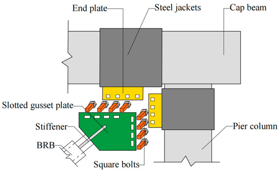
Figure 2.
Configuration of the bolted gusset connection.
2.2. Design of Bolted Gusset Connection
The maximum axial force Pmax of the BRB is used as the force demand for the design of the BRB-RCB, which can be calculated as follows:
where β is the compression strength adjustment factor; Ry, fy and ωy are the material overstrength, nominal yield stress and strain hardening factor of the inner core, respectively; Ac is the cross-sectional area of the core yielding segment.
The generalized uniform force method (GUFM) [24] is adopted to obtain the dimension of the gusset plate in this study, in which there is more freedom in selecting the dimensions of the gusset plate for the designers. For the aim of achieving moment equilibrium, GUFM assumes that the force components on the gusset resulting from Pmax are concentrated on the midpoint of both the gusset-to-beam and gusset-to-column interfaces. The extension lines of force components pass through the ‘beam control point’ and the ‘column control point’ and meet the brace force at the ‘gusset control point’ as shown in Figure 3. According to the force equilibrium requirement for the gusset plate, the gusset-to-column and gusset-to-beam interface forces can be obtained as follows:
where Hub, Vub, Huc and Vuc are the horizontal and vertical forces on the gusset-to-beam and gusset-to-column interfaces, respectively; Lh and Lv are the gusset length and height, respectively; hb and hc are the beam depth and the column depth, respectively; φ is the BRB incline angle.
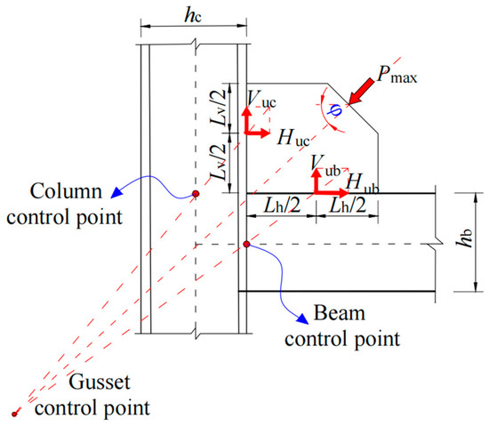
Figure 3.
GUFM [24].
As shown in Figure 4, Whitmore suggested using a column strip with a unit width within the effective width [25] to obtain the gusset thickness tg. The peak stress σc within the effective width be, which is expressed as Equation (2), should be less than the yield strength f of the gusset material.
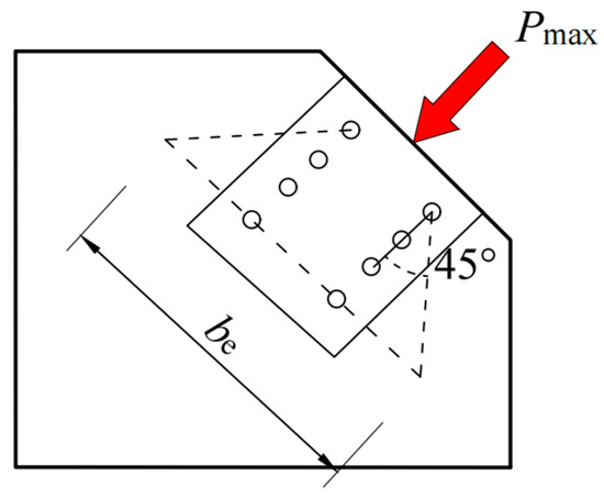
Figure 4.
Effective width method [25].
The compressive strength, Pcr, must meet the requirement specified in the Specification for Structural Steel Buildings [26] as follows:
where E is the elastic modulus of the gusset and r is the radius of gyration of the Whitmore section [25]. The buckling coefficient k = 0.65 when the gusset plate is restrained by free-edge stiffeners, and k = 2 or 1.2 when the gusset plate is susceptible to out-of-plane movement and side-sway buckling. The length of the column strip, Lc, is either the average of the lengths L1, L2 or L3, as presented in Figure 5.
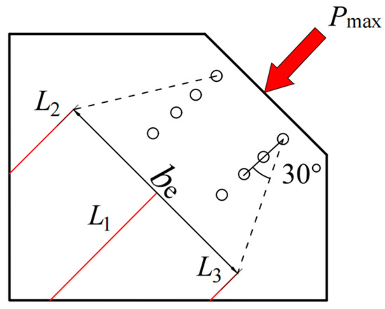
Figure 5.
The analytical model of the gusset plate [27].
According to the standard for the design of steel structures [28], the design shear capacity Nvb for the high-strength bolt can be computed as follows:
where k = 0.7 for the contact force perpendicular to the slot direction; nf is the number of friction surfaces; μ is the friction coefficient; P is the design value of pre-tensile force of the bolt. When the slot direction parallels the gusset interface, the bolt number at the cap beam (nB) and pier column (nC) interfaces can be calculated based on the horizontal and vertical components of the brace force as follows:
The slot length, L, of the gusset plate is expressed as:
where l is the distance between the bolt and foundation (or cap beam bottom); dmax is the maximum design drift of the bridge; dp is the square bolt width.
3. Numerical Study
3.1. Parameters Design
To investigate the effect of the slot direction on the inelastic behavior of the bolted gusset connection, three types of bolts with different sliding directions were adopted, as seen in Figure 6b–d. The joint stiffness may be significantly decreased if the bolt group has an excessive slip. As illustrated in Figure 6e–g, the combination of one horizontal slot and four vertical slots were selected to control the sliding displacement of the bolt group, in which the position of the horizontal slot was alternative. A less costly strategy that was developed was when there was only one group of bolts sliding along the gusset interface (Figure 6h,i). Thus, a total of nine BRB-RCB numerical specimens were constructed by the ABAQUS program [29], and the corresponding details and identifications of the gusset plates are presented in Figure 6. The first two letters of the identifications denote the gusset type. The letters ‘TG’ and ‘NG’ represent the traditionally welded gusset plate and the slotted gusset plate, respectively. The letters ‘V’ and ‘H’ represent the bolts that are allowed to slide in a vertical and parallel direction along the gusset interface, respectively. The letter ‘S’ stands for the inclination angle of 45° between the slot direction and gusset interface. The letters ‘VH’ refer to the combination of vertical and horizontal sliding bolts. The subsequent number in the identifications represents the relative position of the horizontal slot, and the letters ‘B’ or ‘C’ represent the horizontal slots only arranged near the gusset-to-beam interface or gusset-to-column interface, respectively.
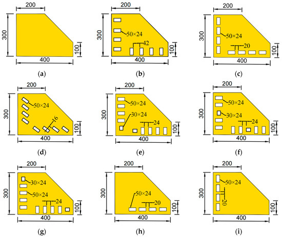
Figure 6.
Details of differently slotted gusset plates: (a) TG; (b) NG-V; (c) NG-H; (d) NG-S; (e) NG-VH-1; (f) NG-VH-3; (g) NG-VH-5; (h) NG-H-B; (i) NG-H-C.
3.2. Finite Element Model
The benchmark model was constructed based on the experimental test of a double-pier RC bridge conducted by Dong et al. [19], of which details are represented in Figure 7a. The column, cap beam, foundation and steel panel zone were modeled using eight-node reduced integration brick elements (C3D8R), of which the mesh sizes were from 6 to 80 mm based on the mesh convergence test. The truss T3D2 element was employed to define the longitudinal rebars, stirrups and BRB. The ‘concrete damaged plasticity’ material model was used for the concrete, and the bilinear material model was used for all longitudinal rebars, stirrups, steels and BRBs.
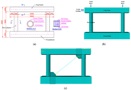
Figure 7.
The benchmark model: (a) Details of the RC double-column bridge; (b) FE model of bare bridge bent; (c) FE model of BRB-RCB.
C40 concrete with a compressive strength of 41.3 MPa was used for the foundation, the columns and the cap beam. HRB335 reinforcement bars with a yielding strength of 392 MPa were adopted for the longitudinal rebars and the stirrups. The bolts were made of S690Q high-strength steel [18], and Q345 and Q235 steel were selected for the steel panel zone and the BRB, respectively, of which the main mechanical indexes are represented in Table 1. The interaction between the rebars and concrete was modeled using the embedded constraint prescribed in ABAQUS, while the bond-slip behavior between them was ignored. The coupling constraint was adopted between the BRB and gusset plate, and the other connections were modeled using the tie constraint.

Table 1.
Mechanical properties of materials [18,19].
With respect to the boundary conditions, the foundation was fully fixed on the ground. To account for the weight of the superstructure, a vertical load corresponding to 20% of the column’s bearing capacity was applied on the top of the cap beam. The lateral cyclic displacement excitation was loaded at the left end of the cap beam. As shown in Figure 8, the imposed story drift was 1/1200, 1/550, 1/200, 1/100, 1/50 and 3/100 [30]. In this study, strength degradation caused by the repeated cyclic load was not the issue of concern, and, thus, only one cycle was carried out at each displacement amplitude. The eigenvalue analysis was initially conducted to obtain the buckling mode, and then the scaled buckling mode from the buckling analysis was imposed on the model as the initial imperfection. Based on Fang et al.’s research [31], a maximum imperfection of 0.01tg was considered in the subsequent nonlinear analysis.
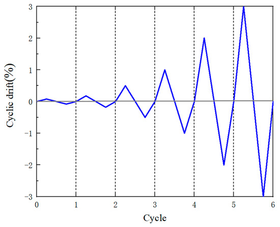
Figure 8.
Loading protocol.
Figure 9 shows the comparison of the hysteretic curve of the double-pier RC bridge model with the test result [19], as well as the comparison of both backbone curves depicted in Figure 10, respectively. From the comparisons of the hysteretic and backbone curves, it can be found that the finite element model accurately predicts the loading stiffness, unloading stiffness and hysteretic behavior using the material properties mentioned above. The results of the parametric study are summarized in Table 2.
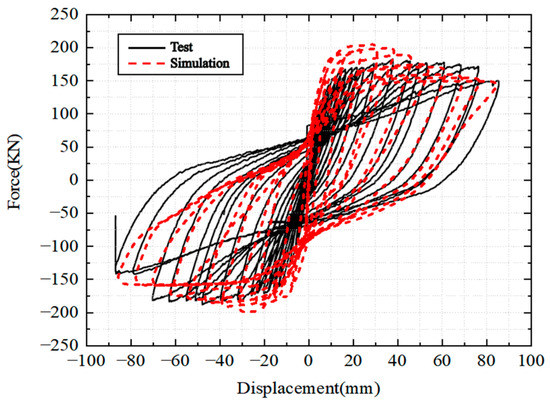
Figure 9.
Numerical vs. experimental hysteretic curves.
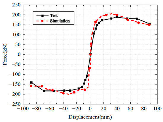
Figure 10.
Numerical vs. experimental backbone curves.
Table 2.
Summary of the parametric study.
4. Results and Discussion
4.1. Slot Direction
Figure 11 shows the comparison of the hysteretic loops of the BRB-RCB with the welded gusset and BRB-RCBs with the bolted gusset connections. Both specimen TG and specimen NG-H exhibited stable hysteretic behaviors, while the pinching effects were observed for both specimens NG-V and NG-S. Specimen NG-V even experienced buckling failure under compression at the last cycle. As seen in Figure 12, a large slip between the bolts and the gusset was found for both specimens TG and NG-H at the fourth cycle, when the lateral restoring force was close to zero. This was the main reason for their decreasing lateral stiffnesses and pinching phenomenon, which also had a negative effect on their energy dissipation capacities. The displacements of the bolts and the gusset were coordinated for specimen NG-H in vertical and horizontal directions (Figure 12). The corresponding elastic stiffness was increased by 2.4% and the cumulative energy dissipation grew by 9.7% compared with specimen TG.
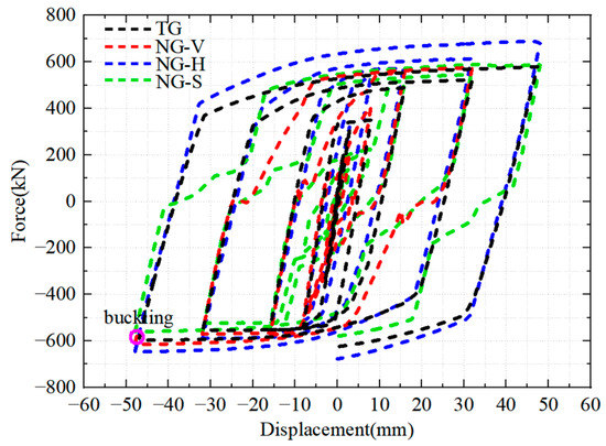
Figure 11.
Comparison of hysteretic response of the BRB-RCB with welded gusset plate and two-sided slotted gusset plate with unidirectional sliding bolts.
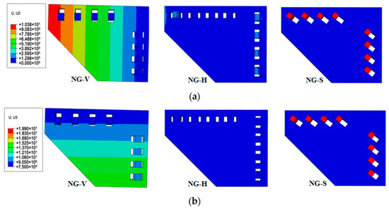
Figure 12.
The (a) vertical and (b) horizontal displacement contours of specimens NG-V, NG-H and NG-S.
Figure 13 demonstrates the Von Mises stress distributions on the gusset interfaces at ±2% drift. The maximum stresses on the gusset-to-column and gusset-to-beam interfaces of the BRB-RCB with the welded gusset plate all exceeded the yield strength of 345 MPa, while the stress distribution at the gusset interfaces were relatively uniform for the other specimens with bolted gusset connections, and the peak stresses of the three slotted gusset plates (NG-V, NG-H and NG-S), compared with the specimen TG, were reduced by 40.7%, 9.2% and 67.1%, respectively. It should be noted that the peak stress had a shift tendency from the gusset corner to the gusset tip at the gusset-to-column interface for the specimen NG-H, which could cause a premature fracture at the gusset tip under greater lateral drift.
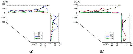
Figure 13.
The Von Mises stress responses along the gusset interfaces at 2% drift: (a) Joint closing; (b) Joint opening.
4.2. Position of the Bolt Sliding Parallel to the Gusset Interface
Figure 14 shows the comparison of the hysteretic curves of BRB-RCBs with the mixed sliding bolts. From Figure 14, it can be drawn that the hysteretic loops were satisfactory and stable, and no pinching effect was observed during the loading process. As seen in Figure 15, few slips between the gusset and the bolt sliding parallel to the gusset interface were found for these three bolted gusset connections, and the resulting slippage of the adjacent bolts sliding toward to the gusset interface was also limited. Therefore, it can be inferred that the decrease in the slippage of the bolt group might have a positive effect on improving the seismic performances of the BRB-RCBs. As detailed in Table 2, the elastic stiffness of specimens NG-VH-1, NG-VH-3 and NG-VH-5, compared to specimen NG-V, increased by 2.1%, 9.4% and 18.2%, respectively. Compared to specimen NG-VH-1, the cumulative energy dissipation of the specimens NG-VH-3 and NG-VH-5 increased by 2.6% and 6.2%, respectively. The main reason that was inferred was that the bolt, sliding parallel to the gusset interface, located closer to the corner of the gusset, experienced larger slippage of the bolt group, resulting in a smaller elastic stiffness and a lower energy dissipation capacity. Conversely, when the limited sliding bolt was positioned nearer to the tip of the gusset, the slippage of the bolt group was reduced, leading to a greater stiffness and a more saturated hysteretic response.
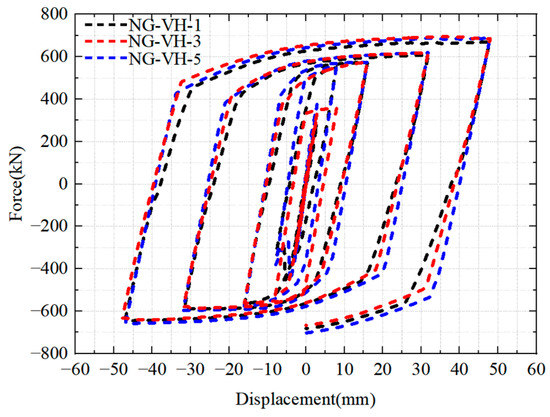
Figure 14.
Comparison of hysteretic responses of the BRB-RCBs with two-sided slotted gusset connection with bidirectional sliding bolts.
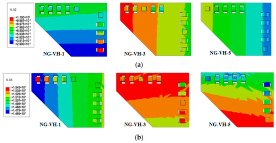
Figure 15.
The (a) vertical and (b) horizontal displacement contours of specimens NG-VH-1, NG-VH-3 and NG-VH-5.
As Figure 16 depicts, the peak Von Mises stresses at the gusset plate interfaces were all less than the yield strength of 345 MPa for the specimens from NG-VH-1 to NG-VH-5 and the maximum stress distributed near the position of the non-slip bolt (Figure 15). This is because the slip ceased when the bolt made contact with the end of the short slot and the stress concentration rapidly developed at this corresponding region. Compared with specimen NG-V, the peak stresses at the gusset interfaces of specimens NG-VH-1, NG-VH-3 and NG-VH-5 increased by 43.2%, 10.8% and 5%, respectively. It indicated that the stress level at the gusset interfaces grew due to the additional non-slip bolt, and the stress level was raised further if the position of the ‘fixed’ bolt moved inward to the gusset corner.
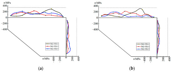
Figure 16.
The Von Mises stress distributions on the gusset interfaces at 2% drift: (a) Joint closing; (b) Joint opening.
4.3. One-Sided Sliding Bolt
According to Table 2 and Figure 17, the elastic stiffnesses of specimens NG-H-B and NG-H-C were 4.8% and 1.7% higher than that of NG-H, while the corresponding cumulative energy dissipation decreased by 7.9% and 4.7%, respectively. As plotted in Figure 18 of the displacement contours in gussets at 1% drift, it can be concluded that the slippage of the bolts, compared with specimen NG-H, was reduced for both specimens NG-H-B and NG-H-C. The peak Von Mises stresses of specimens NG-H-B and NG-H-C at the gusset interfaces decreased 23.5% and 38.1% against specimen NG-H, respectively (Figure 19). This demonstrates that the gusset plate with one-sided sliding bolts has the benefit of reducing the stress level at the gusset interfaces, which can delay the fracture failure of the gusset connection.
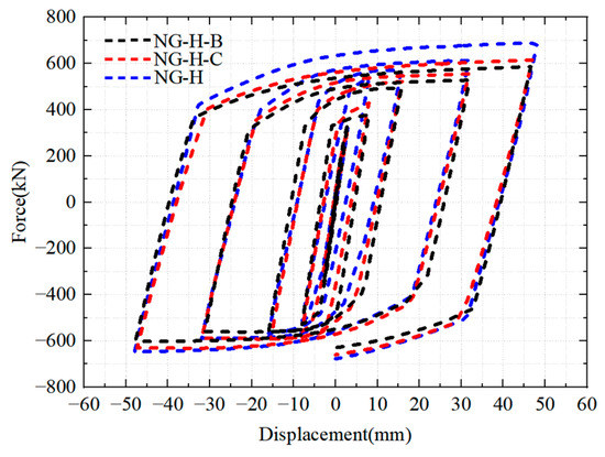
Figure 17.
Comparison of hysteretic response of specimen NG-H and those with one-sided slotted gusset connection.
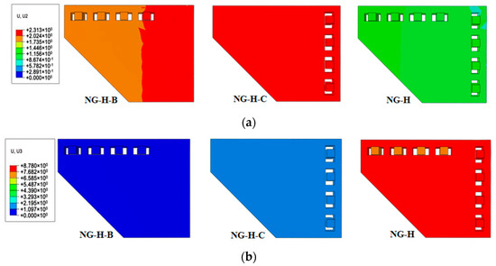
Figure 18.
Comparison of displacement contours in specimens NG-H, NG-H-B and NG-H-C: (a) vertical; (b) horizontal.
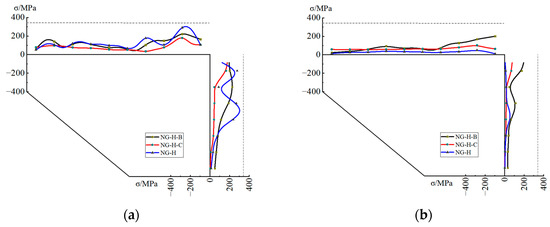
Figure 19.
Comparison of Von Mises stress distributions for specimens NG-H, NG-H-B and NG-H-C: (a) Joint closing; (b) Joint opening.
4.4. Cumulative Equivalent Plastic Strain near Column Ends
Previous BRB-RCB tests [21,22] have demonstrated that the severe cracking, appearing on the columns connected with the welded gusset plates, might be caused by the significant plastic responses near the column ends. In this section, the cumulative equivalent plastic strain (PEEQ) contours of the columns at 2% and 3% drift, respectively, are presented in Figure 20 and Figure 21 to investigate the effect of different gusset connections on the damage of RCBs. From Figure 20 and Figure 21, it can be drawn that the plastic responses were located near both ends of the pier column for the RCBs without BRBs. As for the BRB-RCBs with the welded gusset connection and bolted gusset connection, the top hinges were shifted from the column top to near the gusset tip due to the rigid gusset zone effect.
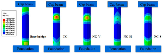
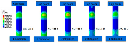
Figure 20.
PEEQ on right pier columns at 2% drift.
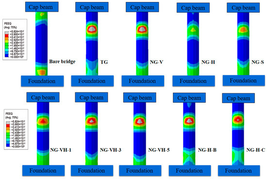
Figure 21.
PEEQ on right pier columns at 3% drift.
As plotted in Figure 20 of the PEEQ value of the column at the 1/50 drift ratio, the plastic responses of the right pier column near the gusset tip can be successfully controlled by adopting the bolted gusset connection. As the story drift increased to 3%, as shown in Figure 21, the plastic hinges have been developed in the columns except for specimen NG-H. Compared with specimen TG, the damage level of the models with bolted gusset connections can be further decreased. Specimen NG-H experienced the lowest plastic damage among all BRB-RCBs, followed closely by specimen NG-S, while specimen NG-H has the highest PEEQ value. With regards to the BRB-RCBs with slotted gusset plates suiting the mixed bolts, the right pier column suffered higher PEEQ strains when the non-slip bolt was located closer to the gusset tip. The major reason was that a greater frame-to-gusset interaction was induced as the non-slip bolt located further from the gusset corner. Both models with one-sided sliding bolts also sustained severe plastic responses near the gusset tip, although their stress levels at the gusset interfaces were relatively low as prescribed in Section 4.3. It indicates that simply reducing the slipping of the bolt group has a poor effect on controlling the plastic damage of the pier column.
5. Conclusions
Three types of bolted gusset connections, featuring a two-sided slotted gusset plate with unidirectional sliding bolts, two-sided slotted gusset plate with bidirectional sliding bolts and one-sided slotted gusset plate configurations, respectively, were developed to reduce the negative opening–closing action effect on the seismic performance of BRB-RCBs. Finite element analysis was used to investigate their column–gusset–BRB interactions and the corresponding plastic responses. Comparisons were made between three strategies and the traditional one. The main conclusions can be drawn as follows based on the numerical results:
(1) A strong opening–closing effect on the BRB-RCB was induced by the constraint between the welded gusset connection and its adjacent beam–column zone under severe earthquake conditions. The proposed bolted gusset connection consisted of a slotted gusset plate, end plates, square bolts and steel jackets, which effectively released the frame action through the sliding of the bolt group, as well as improved the seismic behavior of BRB-RCBs.
(2) No shear failure of the cap beam or buckling failure of the gusset-to-BRB connection (except for the specimen NG-V) was found during the loading process, which indicated that the bolted gusset connection could delay the shear failure of the concrete beam and provide enough stiffness on the BRB-to-gusset connection. Meanwhile, the bolted gusset connection configuration was relatively simple and easy to construct, as well as being suitable for both the new and as-built structures.
(3) BRB-RCBs with bolted gusset connections exhibited satisfactory and stable hysteretic responses, except for specimens NG-V and NG-S because of their excessive slippages of the bolt group. Among all BRB-RCB models, three specimens with the bidirectional sliding bolt group had the better energy dissipation capacity, while the lateral stiffnesses of the specimens with a one-sided slotted gusset plate were relatively high.
(4) Compared to the BRB-RCB model with the welded gusset plate, the Von Mises stress at the gusset interfaces could be significantly reduced by adopting the slotted gusset plates, with a maximum decrease of 80.7% in the gusset-to-column interface, which would delay the rupture failure in the gusset plate connections.
(5) By employing the bolted gusset connection, the plastic response level at the columns could be successfully decreased. The primary plastic hinges were formed and further developed on the top of the column near the gusset tip when story drift increased from 2% to 3%. The specimen NG-H had the lowest PEEQ value, which was even less than that of the bare bridge.
Author Contributions
Conceptualization, J.L. and P.C.; methodology, G.X.; software, P.J.; validation, P.J.; writing—original draft preparation, P.J.; writing—review and editing, J.L. All authors have read and agreed to the published version of the manuscript.
Funding
This research was funded by the National Natural Science Foundation of China (Grant Nos. 51978213, 51778190), the Scientific Research Fund of the Institute of Engineering Mechanics, China Earthquake Administration (Grant No. 2020D04) and the Natural Science Foundation of Heilongjiang Province (Grant No. LH2022E005).
Data Availability Statement
No new data were created or analyzed in this study.
Conflicts of Interest
The authors declare no conflict of interest.
References
- Chen, R.; Qiu, C.X.; Hao, D.X. Seismic response analysis of multi-story steel frames using BRB and SCB hybrid bracing system. Appl. Sci. 2020, 10, 284. [Google Scholar] [CrossRef]
- Sosorburam, P.; Yamaguchi, E. Seismic retrofit of steel truss bridge using buckling restrained damper. Appl. Sci. 2019, 9, 2791. [Google Scholar] [CrossRef]
- Freddi, F.; Tubaldi, E.; Zona, A.; Dall’Asta, A. Seismic performance of dual systems coupling moment-resisting and buckling-restrained braced frames. Earthq. Eng. Struct. Dyn. 2021, 50, 329–353. [Google Scholar] [CrossRef]
- Naqi, A.; Roy, T.; Saito, T. Time-dependent damage estimation of a high-rise steel building equipped with buckling-restrained brace under a series of earthquakes and winds. Appl. Sci. 2021, 11, 9253. [Google Scholar] [CrossRef]
- Zhang, A.L.; Wang, H.W.; Jiang, Z.Q.; Guo, K.; Niu, Z.Y. Numerical simulation analysis of double yield points assembled buckling-restrained brace with replaceable inner core. Structures 2022, 35, 1278–1294. [Google Scholar] [CrossRef]
- Jiang, Z.Q.; Dou, C.; Guo, Y.L.; Zhang, A.L. Theoretical study on design methods for pinned assembled BRB with flat core. Eng. Struct. 2017, 133, 1–13. [Google Scholar] [CrossRef]
- Zhao, J.X.; Wu, B.; Ou, J.P. Flexural demand on pin-connected buckling-restrained braces and design recommendations. J. Struct. Eng. 2012, 138, 1398–1415. [Google Scholar] [CrossRef]
- El-Bahey, S.; Bruneau, M. Buckling restrained braces as structural fuses for the seismic retrofit of reinforced concrete bridge bents. Eng. Struct. 2011, 33, 1052–1061. [Google Scholar] [CrossRef]
- Upadhyay, A.; Pantelides, C.P.; Ibarra, L. Residual drift mitigation for bridges retrofitted with buckling restrained braces or selfcentering energy dissipation devices. Eng. Struct. 2019, 199, 109663. [Google Scholar] [CrossRef]
- Xiang, N.; Alam, M.S. Displacement-based seismic design of bridge bents retrofitted with various bracing devices and their seismic fragility assessment under near-fault and far-field ground motions. Soil. Dyn. Earthq. Eng. 2019, 119, 75–90. [Google Scholar] [CrossRef]
- Shi, Y.; Zhong, Z.; Qin, H. Toggle buckling-restrained brace systems and a corresponding design method for the seismic retrofit of bridge bents. Eng. Struct. 2020, 221, 110996. [Google Scholar] [CrossRef]
- Shi, Y.; Zhang, Z.; Fan, X. Seismic design and performance analysis of bridge bents retrofitted with multistage buckling-restrained braces. Structures 2023, 49, 779–791. [Google Scholar] [CrossRef]
- Chou, C.C.; Liu, J.H.; Pham, D.H. Steel buckling-restrained braced frames with single and dual corner gusset connections: Seismic tests and analyses. Earthq. Eng. Struct. Dyn. 2012, 41, 1138–1156. [Google Scholar] [CrossRef]
- Lin, P.C.; Tsai, K.C.; Wu, A.C.; Chuang, M.C. Seismic design and test of gusset connections for buckling-restrained braced frames. Earthq. Eng. Struct. Dyn. 2014, 43, 565–587. [Google Scholar] [CrossRef]
- Bai, J.L.; He, J.; Li, C.; Jin, S.S.; Yang, H. Experimental investigation on the seismic performance of a novel damage-control replaceable RC beam-to-column joint. Eng. Struct. 2022, 267, 114692. [Google Scholar] [CrossRef]
- Chen, H.M.; Bai, J.L. Seismic performance evaluation of buckling-restrained braced RC frames considering stiffness and strength requirements and low-cycle fatigue behaviors. Eng. Struct. 2022, 267, 114692. [Google Scholar] [CrossRef]
- Fahnestock, L.A.; Ricles, J.M.; Sause, R. Experimental evaluation of a large-scale buckling-restrained braced frame. ASCE J. Struct. Eng. 2007, 133, 1205–1214. [Google Scholar] [CrossRef]
- Fatemi, H.; Aghakouchak, A.A. Design and numerical evaluation of two innovative moment-free beam-gusset-column connections for BRBFs. J. Constr. Steel Res. 2021, 184, 106837. [Google Scholar] [CrossRef]
- Dong, H.; Du, X.; Han, Q. Hysteretic performance of RC double-column bridge piers with self-centering buckling-restrained braces. Bull. Earthq. Eng. 2019, 17, 3255–3281. [Google Scholar] [CrossRef]
- Dong, H.; Du, X.; Han, Q.; Bi, K. Numerical studies on the seismic performances of RC two-column bent bridges with self-centering energy dissipation braces. J. Struct. Eng. 2020, 146, 04020038. [Google Scholar] [CrossRef]
- Bazaez, R.; Dusicka, P. Cyclic behavior of reinforced concrete bridge bent retrofitted with buckling restrained braces. Eng. Struct. 2016, 119, 34–48. [Google Scholar] [CrossRef]
- Bazaez, R.; Dusicka, P. Performance assessment of multi-column RC bridge bents seismically retrofitted with buckling-restrained braces. Bull. Earthq. Eng. 2018, 16, 2135–2160. [Google Scholar] [CrossRef]
- Zhao, J.X.; Zhang, J.G.; Song, J.Y. Sliding gusset connections for improved seismic performance of BRB-RC frame: Damage-control design and subassemblage tests. Eng. Struct. 2023, 282, 115828. [Google Scholar] [CrossRef]
- Muir, L.S. Designing compact gussets with the uniform force method. Engineering 2008, 45, 13. [Google Scholar]
- Whitmore, R.E. Experimental Investigation of Stresses in Gusset Plates; Bulletin No. 16. Engineering Experiment Station; The University of Tennessee: Knoxville, TN, USA, 1952. [Google Scholar]
- American Institute of Steel Construction (AISC). Specification for Structural Steel Buildings; American Institute of Steel Construction: Chicago, IL, USA, 2016. [Google Scholar]
- Thornton, W.A. Bracing connections for heavy construction. Engineering 1984, 21, 139–148. [Google Scholar]
- GB 50017-2017; Standard for Design of Steel Structures. China Building Industry Press: Beijing, China, 2018.
- Abaqus, S. CAE 6.20 User’s Manual Dassault; Systémes Inc. Provid.: Johnston, RI, USA, 2020; Volume IV. [Google Scholar]
- GB 50011-2010; Code for Seismic Design of Building. China Building Industry Press: Beijing, China, 2010.
- Fang, C.; Yam, M.C.H.; Zhou, X. Post-buckling resistance of gusset plate connections: Behaviour, strength, and design considerations. Eng. Struct. 2015, 99, 9–27. [Google Scholar] [CrossRef]


Disclaimer/Publisher’s Note: The statements, opinions and data contained in all publications are solely those of the individual author(s) and contributor(s) and not of MDPI and/or the editor(s). MDPI and/or the editor(s) disclaim responsibility for any injury to people or property resulting from any ideas, methods, instructions or products referred to in the content. |
© 2023 by the authors. Licensee MDPI, Basel, Switzerland. This article is an open access article distributed under the terms and conditions of the Creative Commons Attribution (CC BY) license (https://creativecommons.org/licenses/by/4.0/).