Featured Application
The presented work assesses the impacts of electric bus charging on both the transportation network and utility grid. It is developed to help placing and sizing charging infrastructures while electrifying existing bus fleets.
Abstract
The transition from diesel to electric buses allows the reduction of greenhouse gas emissions. However, the impacts of charging strategies on the quality of bus services and the utility grid must be assessed to ensure the feasibility of the energy transition in the public transportation sector. This study investigates the performances of different locations and sizes of charging infrastructures by presenting the comprehensive modelling of a bus network. It also estimates the potential benefits of a local photovoltaic (PV) production to reduce negative impacts on the utility grid. The presented approach is used for modelling one urban bus line in Compiègne, France, and simulations are performed for various case studies. The results demonstrate that the proposed method allows analysing the impact of the charging process on the quality of bus services by determining the delays of arrivals. The simulations also show the impacts of charger placement on bus on-board battery capacity, total peak power demand of battery charging, and PV self-consumption ratio. The amount of PV energy used directly to charge buses remains low, although it varies between scenarios. PV energy during winter is not sufficient to fully charge buses; however, it can be enough with additional stationary storage in the summer.
1. Introduction
Urban public transport is essential for carrying millions of people for their daily trips; however, it has a significant impact on greenhouse gas (GHG) emissions. Therefore, the electrification of urban buses is an efficient way to reduce emissions, as long as the supplied electricity is provided by low carbon energy sources. Additionally, electric buses (EBs) provide supplementary benefits compared to conventional buses such as a reduction of air pollution (fine particle matter), noise, and on-board vibrations [1]. Their maintenance is also easier and cheaper; however, the integration of EBs is a challenging procedure due to the increased power demand which adds additional stress to the electricity network.
The location of charging infrastructures and charging periods can induce negative impacts on the utility grid. The three main locations for static-charging infrastructures are bus depots, line terminals, and bus stops. Most of the time, EBs are charged at the bus depot during the night [2]. Therefore, buses require sufficient battery capacity to perform their daily service of around 200–300 km [3]. The consumption of an EB varies between 0.76 and 2.79 kWh/km for a standard bus with an average of 1.65 kWh/km [4]. Therefore, at least 150 kWh battery capacity is required to complete the daily service. Such an on-board battery pack weights approximately one ton considering the energy density around 150 Wh/kg for lithium-ion batteries. Ji et al. have shown that an increase of the on-board battery capacity from 50 kWh to 400 kWh induces a raise in the bus’ energy consumption by 25% [5]. A larger battery capacity will thus increase the available energy to perform a long trip without frequently charging the battery. However, it will also lead to an increased energy consumption due to higher bus weight. Battery capacity has also an impact on the capacity of passengers, as a higher battery capacity requires more space in the bus [6]. The TOSA project has shown that decreasing the battery capacity leads to a reduction on the battery weight by 5–7 tons, an increase of the passengers’ capacity of 15–30%, and a reduction in the energy consumption of 10% [7].
Charging at the bus depot is usually performed once per daily service during several hours in the night at a power of 24–180 kW [1]. Currently, the majority of EB fleets is very small, around 15 EBs per bus fleet in Europe [2] and 6 in the United States [8]. However, in the future, the penetration of a higher number of EB fleets is expected, hence a higher amount of power consumption will most likely be observed during the night period. Although it is not a peak power consumption period for the utility grid, charging during the night might prevent transformers from cooling down and accelerating the degradation of these units.
Alternatively, EB batteries can also be charged on-route at line terminals or bus stops (also called opportunity charging). Charging at terminals can occur around 20 times per daily service for a few minutes at a power of 150–600 kW [1]. On the other hand, charging at bus stops can occur around 200 times per daily service for a few seconds at a power up to 600 kW. From this perspective, the on-board battery capacity can be reduced with on-route charging, and it will lead to lower bus energy consumption. However, the short charging times imposed by passengers’ transportation require high power to supply enough energy to the bus battery in a few seconds/minutes. A significant number of EBs in the fleets could impact the stability of the utility grid and create a risk of increasing the peak power consumption in the local area. A large number of EBs could also cause an overloading of utility grid transformers and induce the use of carbon-based fuel supplies, which release high GHG emissions.
One solution to reduce the impacts on the utility grid is to produce electricity locally with photovoltaic (PV) panels. If the EBs charge during the daylight, the PV production can reduce the bus consumption peak. On the other hand, if they charge during the night, an additional stationary battery could help to reduce grid impact by storing surplus PV production during the day to use it at night. The charging scenario must be adapted in order to maximize PV self-consumption ratio, i.e., to increase the percentage of the bus load covered by the PV production. However, charging during the daylight at a low power to maximize PV self-consumption ratio might induce additional charging time, which can cause delays in the service. All of these factors show that the location and the size of charging infrastructures, as well as the charging strategy, can have a significant impact on both the utility grid and the transport network, which need to be carefully analysed with a detailed model of the bus transportation network.
The aim of this study is to focus on the influence of sizing and placement of charging infrastructures on both the utility grid and transportation network. This preliminary study simulates a bus fleet operation with several scenarios, which differ according to the location of chargers (depot, terminals, or stops) and their rated power. First, the bus network is modelled and the operation of buses is simulated. After that, charging stations are placed on the transportation network—at depot, terminals, or stops—and charging rules are applied. Performance indicators are defined to compare studied configurations. The main contributions of this work are listed as follows:
- A bus consumption model that considers the influence of the battery capacity on the bus gross weight and thus on the bus consumption;
- Modelling of a bus network is presented based on General Transit Feed Specification (GTFS) data;
- A sequential simulation of the EB operation is performed in order to analyse the influence of the charging scenarios on the quality of transportation services (delay indicator);
- A comparison between bus energy demand and PV production in order to assess the potential of PV energy to reduce impacts of EB charging on the utility grid.
The rest of the paper is structured as follows. Section 2 analyses the scientific literature to underline the research gaps. Section 3 presents the modelling and simulation approach for the buses’ operation and charging. The case study is introduced in Section 4. Section 5 displays the simulation results, and Section 6 analyses them. Finally, Section 7 contains a conclusion and perspectives for future works.
2. State of the Art of Scientific Literature
This section analyses the scientific literature to underline trends and gaps. The literature survey focuses on public transport planning, sizing of EB charging infrastructures, and PV supply of charging stations.
2.1. Research Positioning
The planning of public transportation can be divided into three main phases: strategic (horizon of years), tactical (one year to days), and operational (real time). As described by Perumal et al. [9], the planning process starts by determining the infrastructure, the lines, the frequencies, and the bus fleet investment. The tactical planning phase consists of the definition of the timetables, the vehicle scheduling (assignation of buses to the timetabled trips), the crew scheduling, and eventually the crew rostering. Recovery plans and real-time control strategies are also often implemented to reduce the impact of disruptions.
From a transportation point of view, the present study concerns the strategic planning (sizing and placement of charging infrastructures) and its impact on the operational planning (e.g., bus delay). According to Manzolli et al. [10], EB studies can be divided into five categories: vehicle technology, battery technology, energy management, fleet operation, and sustainability. The present research concerns both the vehicle technology, in particular the charging power, and the fleet operation.
2.2. Sizing of Charging Infrastructures
Scientific publications about EB charging either focus on the infrastructures’ sizing [11] and/or the scheduling of the battery charging power [12,13]. A charging strategy can be defined as the choices of charging frequency, power, start time, and duration [6]. Few studies tackle both the sizing and management problems. Gao et al. [14] compared the impact of normal charging at 90 kW and ultra-fast charging at 480 kW on the on-board battery capacity for improving the autonomy of the bus. Fast charging has been shown to reduce the battery capacity and increase the autonomy. Leone et al. [15] have demonstrated that two 150 kW charging stations and an opportunity charger of 350 kW are needed at the terminals in order to reduce the cost and environmental impact compared to current diesel buses. Hasan et al. [16] have focused on the energy management of the bus and the charging strategy. The developed “ECO-charging” strategy, using pulsed charging to lessen the battery cooling needs, reduces the average grid load by more than 10% and shifts the charging to off-peak periods. On the other hand, a two-phase optimization framework is proposed to size the charging infrastructure and schedule the charging of EBs with the objective to minimize the total system cost in [6]. The developed rolling-horizon-based charging strategy, which adjusts charging scheduling in real-time based on EB consumption and travel time, reduces the total charging cost by 68.3% compared to uncontrolled charging. In several studies, the sizing of a battery storage is combined with the determination of charging schedules [17,18,19]. Most studies only consider the sizing of the charger’s rated power and the capacity of stationary storage. They usually consider that the size of the on-board battery of the bus is known. However, Ref. [6] investigated the charger deployment, the on-board battery capacity, the charging schedules, and charging costs, and the study shows the importance of considering the on-board battery.
Many studies about EB charging consider the influence on transportation or on the utility grid, but not both at the same time [20]. For example, in order to improve the traffic, Bie et al. have analysed passenger loading to optimize the vehicle scheduling plan, locations of starting, and terminal stations for short-turning lines and charging strategies [21]. The proposed strategy led to reduce the total passenger travel time (dwell times at stops and inter-stop travel times) of 15%. On the other hand, Akaber et al. have considered mainly grid constraints to optimize the objectives of bus operators such as load balancing via peak shaving and cost minimization with load shifting [22]. The presented methodology is achieved to reduce the peak consumption and total charging cost by 50% and 27%, respectively. Lin et al. optimized the bus planning process considering jointly the transportation system and utility grid [23], and Tomizawa et al. studied the feasibility of simultaneously minimizing the power and the energy of surplus PV production [24]. Both studies showed that joint optimization reduces the charging cost, prevents later conflicts between transportation objectives and electricity network constraints, and increases the rate at which EBs charge using local renewable energy.
2.3. Photovoltaic Integration for Bus Charging
Charging infrastructures of EBs are often supplied only by the utility grid [25]; however, Arif et al. also included local PV production and/or electricity storage in order to improve the energy management [26]. Regarding a PV-storage-based charging station at the depot, the authors showed that limiting the supplied power from the grid to 5 kW can maximize the bus depot operator profit while minimizing the charging power causing transformer overloading. Rafique et al. also presented an optimal energy management system using a weighted multi-objective stochastic optimization to minimize the cost of electricity while aiming to reduce battery degradation [27]. Zhuang et al. studied the stochastic energy management of bus charging stations for reducing charging costs with PV production and battery storage considering bus-to-grid energy flows [28]. Szczesniak et al. adopted another point of view, attempting to find an optimal bus charging schedule at line terminals or depots in order to locally smooth the PV production fluctuations [29]. The proposed method was compared to uncontrolled charging and a cost minimization strategy. Results showed that operating costs increased marginally compared to the cost minimization strategy, but that utility grid power fluctuations were significantly reduced.
Concerning the design of PV power plants related to battery charging of EBs, Santos et al. focused on the suitable locations of PV implantation at bus shelters [30]. Based on the solar irradiation, the potential of each bus shelter in Lisbon to supply electronic devices with PV panels was analysed. Almost 54% of bus shelters were found to be able to receive small devices such as lighting or remote small-scale sensors, but only 4% could provide at least 100 W and 2.4 kWh per day in order to supply a refrigerated vending machine. Dalala et al. performed an economic and environmental feasibility study about the installation of PV panels near a bus route [25]. With the right placement of PV panels, supplying EBs with PV panels was found economically and environmentally interesting. However, the investment cost can be huge, as shown by Islam et al. who designed an off-grid PV system to balance the consumption of a bus depot in Malaysia [31]. Sizing results showed that 7350 PV modules (6.5 MWp in total), a battery capacity of 118,200 Ah, and 23,200 m area were needed to offset a peak demand of 466.5 kW. Ren et al. [32] determined the optimal size and location of rooftop PV panels and capacity of storage near the line terminals of neighboring communities. A case study in Hong Kong showed that the infrastructure (PV and stationary battery) deployment achieved the shortest payback period of 3.98 years and addressed the design issues such as battery oversizing with PV and battery misallocation. In [33], Ren et al. focused on the optimization of the charging strategy in the same community-based bus network to increase the on-site consumption of PV production. All of these studies have showed the importance of both infrastructure location and charging strategy to lower the cost.
2.4. Discussion on the State of the Art
The literature review shows that the sizing of charging infrastructures and the management of the charging process have a significant influence on the economic and the environmental performances of the bus charging. Many studies tackle the sizing or the management problems, but rarely both at the same time. Similarly, impacts of EB charging on the utility grid and the transport network are not simultaneously considered, although the deployed charging strategies have significant impacts on both networks. Joint consideration of these two aspects could show benefits for the integration of renewable energy.
Several papers analysed the integration of PV panels and stationary energy storage system to charge EBs with reduced GHG emissions. Where PV production on bus shelters seems insufficient to supply bus energy consumption, large power plants at the depot show opportunity for balancing the energy consumption or reducing the peak demand. The designed infrastructures present a reduced energy cost but a higher investment cost compared to a diesel bus network. The sizing and the placement of charging infrastructures and PV production have an influence on both electricity and transport networks. Therefore, it is important to model the EBs’ network and operation precisely in order to identify the various impacts.
3. Modelling of the Bus Transportation Network
In this section, the modelling approach of the transportation network is presented to determine the charging powers and time delays of EBs. First, the technical terms used to characterize the bus network are defined, then the utilized input data are presented with the deployed models and the simulation approach. The modelling steps are presented in Figure 1. The inputs represent the bus network, the bus fleet operation, the solar irradiation, and the assumptions made on the bus technology and the charging infrastructures. General Transit Feed Specification (GTFS) data are used for modelling the bus network accurately. Models of bus consumption, charging process, and PV production are then integrated into a simulation process to analyse the operation of a bus fleet.
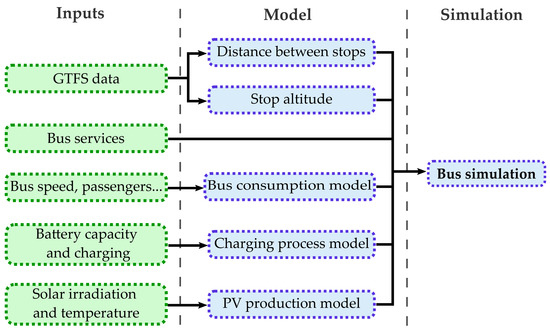
Figure 1.
Flow chart of the modelling approach with the inputs and the computation steps.
3.1. Definitions
Several specific terms which are used for the modelling of bus transportation network are introduced to ease the comprehensibility of the presented method (see Figure 2). The first components of a bus network are bus stops where the bus will stop during the day to board or alight passengers. The travel of a bus from one stop to another is named as a segment. A succession of segments is a route defined by its ordered sequence of stops. A route can belong to various bus lines that are official paths with intermediate stops between one or several terminals at the end of a line.
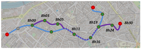
Figure 2.
Scheme of a bus line with three terminals (in red), intermediate bus stops (in green), two routes (in blue and purple), and the time schedule of one trip on the purple route.
Public transport along a line is characterized by a timetable which indicates the times when a bus will stop at each bus stop. Based on the timetable, bus operators define the different bus trips that are combinations of routes and time sequences. This means that a bus can run through the same route several times during the day; however, each time will represent a different bus trip. Eventually, the succession of trips represent the daily service. Services can vary according to the period of the year (e.g., weekdays, weekends, or bank holidays). A service is composed of commercial trips and deadheading ones such as travelling from a bus depot to the beginning of a line without carrying passengers. These terms are illustrated on Table 1, which is the timetable of the bus line “ARC Express” in Compiègne, France [34]. The first column shows the stop sequence for bus line ARC Express, from the “Gare” terminal to the “Aramont” terminal. Then each column is a bus trip, starting at a different time. It can be noticed that bus trips 1, 2, 3, 6, 10, and 11 correspond to the same stops sequence, as well as trips 4, 5, and 7. Therefore, 11 trips are represented on the table with only 4 routes. These trips are assigned to the services of two buses, represented on the first row. It is worth noticing that studies may use a different vocabulary to present the bus transportation network from a passenger point of view.

Table 1.
Timetable of bus line “ARC Express” in Compiègne, France [34].
3.2. Bus Consumption Modelling
EB energy consumption varies according to several parameters: bus speed, weight, traffic, number of passengers, road slope, etc. Bus consumption also depends on heating, ventilation, and air-conditioning (HVAC), and other auxiliaries, as well as on the implementation of a deceleration and braking energy recovery system. Therefore, a bus consumption model is needed to assess the energy demand of each EB in the fleet. Physical (also called white-box) models rely on the analysis of physical and chemical processes in the energy transmission and storage components of the vehicle [35]. Data-driven (also called black-box) models deduce the bus consumption based on large amounts of experimental or real-world operation data [35]. Eventually, intermediate grey-box models combine experimental data with mechanical insight [36].
3.2.1. Consumption Model
Data-driven models require gathering a high amount of data, which can be collected through sensors. High-resolution data can be used [37,38], but they are often hard to collect and replicate for other locations. Low-resolution data [39] can also be used; however, they decrease the accuracy of the consumption model. Comparatively, physical models apply Newton’s second law of motion in order to model the electricity consumption of EB. In this category, longitudinal dynamic models consider only the traction of the bus and require driving profiles of EBs as input (i.e., a time series of velocity and elevation) [40]. Jefferies and Göhlich [41] have indicated that driving profiles may come from real-world operation [14] or standard dynamometer driving cycles [42,43]. Moreover, HVAC and other auxiliaries’ consumption (lighting and other support systems) can be also considered for more detailed modelling of an electricity consumption profile [44,45,46,47].
This paper implements an existing physical model [35]. The model needs to be fast enough to compute, to require accessible data, and to take into account both the traction and the auxiliaries’ consumption, considering the influence of the latter on the bus’ consumption. It should be noted that the presented method does not consider the regenerative braking, the curves of the road, the number of crossroads, the meteorological conditions, ord the driver’s behaviour. The total consumed power by the bus is defined by Equation (1) as the sum of the power needed for vehicle motion and for auxiliary systems at each time step t.
where is the bus speed, is the mass of the bus, m/s is the standard acceleration of gravity, is the slope, is the coefficient of rolling resistance, kg/m is the air density, is the frontal area of the bus, and is the drag coefficient. The auxiliary consumption is modelled as the sum of the consumption of HVAC (the sum of and [35]) and the other auxiliaries . It should be noted that the total bus weight consists of the bus curb (), battery pack (), and the total number of passengers () inside the bus at time t.
3.2.2. Speed Profile
The speed of the bus must be determined based on the distances and travel times between bus stops taken from the GTFS data in order to calculate the power consumption. Inspired by SORT standard driving cycles [48,49,50], the present paper considers a speed profile with a trapezoid shape between two consecutive bus stops, as seen on Figure 3.
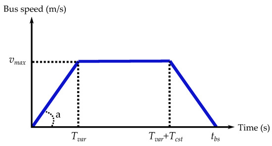
Figure 3.
Bus speed profile in trapeze representing the travel between two bus stops.
The trapezoid is defined by the maximal speed and the acceleration a. Travel time and the distance between two bus stops and are determined using GTFS data. The spatial and temporal constraints of the bus travel can be determined from the speed profile. The distance between the consecutive stops is therefore determined as follows:
where and are the distances travelled during the acceleration/deceleration and constant speed phases, respectively. is the acceleration/deceleration time, is the time at constant speed, and is the bus speed. The time to travel between the two stops is described below:
Therefore, using Equations (7) and (8) with the value of discriminant of the quadratic equation , the maximal speed is determined by
If a delay is anticipated for arriving to the next stop on the route, the EB is assumed to increase its speed and acceleration up to limits. If the maximal speed—computed based on the real departure time of the bus from one stop and the theoretical arrival time to another—is above the speed limit, the speed is capped to a maximal value and a new acceleration is computed. If the new acceleration is also above its limit, then it is capped to and the bus is considered to be late arriving to the next stop.
3.3. Modelling of Charging Process
The state of charge (SoC) of the bus battery at each time t depends on the bus consumption and the charged energy. The evolution of is determined by
where is the power consumed by the bus (negative), is the power used for battery charging (positive), is the EB battery capacity, and and are, respectively, the minimal and maximal SoC limits of the EB battery.
3.4. PV Production
PV power is considered to be utilized for a local and clean energy source for charging the EB’s battery. The PV power is determined according to [51] as below:
where is a yield considered to represent the system losses in the cables and converters, is the PV power at standard test conditions (STC), is the number of PV panels, is the solar irradiation, is the standard solar irradiation value at STC, is the power temperature coefficient of PV module, is the PV cell temperature, is the ambient temperature, is the nominal operating cell temperature of PV module, is the fixed air temperature at NOCT condition, and is the fixed solar irradiation at NOCT condition.
3.5. Bus Network Modelling
This subsection deals with the modelling of the network, which consists of the bus stops, routes, trips, services, and lines. The GTFS data format is used in order to analyse the operation of the bus fleet on a transportation network.
3.5.1. GTFS Data
The GTFS format was initially developed by Google and has since become a de facto standard. Open data in GTFS format are generated by urban transport organizing authorities. They are composed of several tables gathering information about bus schedules and line topography [52] via various text files.
The major advantages of GTFS files are that they are open access and the data are provided in the same format for the transportation network of different cities. However, they must be combined with a description of bus services to simulate the operation of buses. The location information (i.e., latitude and longitude) of bus stops can be found in GTFS data but the distances and slopes between stops must be computed with the post-treatment as in the following section.
3.5.2. Post-Treatment of GTFS Data
The GTFS data are used to determine the list of all routes and trips. As GTFS data only consider trips to model buses’ operations and do not use the concept of routes defined in Section 3.1, all trips must be analysed to identify their corresponding route. After that, the distance between consecutive stops of each route is determined using Open Street Map, which is a free editable geographic database of the world [53]. The elevation of each stop is retrieved from Open Elevation Software. GTFS data also allows analysing the time spent between two consecutive bus stops. This duration can vary during a day mainly due to the hourly/daily traffic conditions.
Firstly, the distance between stops are determined. Based on the latitude and longitude information, a path between two bus stops is generated on Open Street Map using a “bus” transportation mode. To generate the path, Open Street Map creates a sequence of intermediate points on the road between the two stops with a higher density in curved portions (see Figure 4), and defines the total distance as the sum of distances between each intermediate point. This matches quite accurately the real path of the bus; however, it requires manual verification that the path proposed by Open Street Map fits the one on the bus network map.
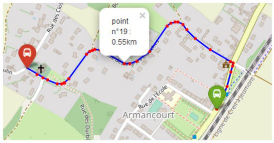
Figure 4.
Path between two bus stops generated using Open Street Map with intermediate points.
Secondly, determination of the altitude is performed. The bus consumption also depends on the slope of the road. Therefore, the Open Elevation software has been used to compute the altitude of all stops based of their latitude and longitude [54]. However, only the mean slope between consecutive stops is accessible in this way. The limit is the resolution of topographic map, around 200 m for open-source maps. This means that all points in a square of 200 m per side will have the same altitude, and that slope variations in this area might be hidden.
3.6. Simulation of the Operation of Buses
The operation of bus trips is defined by timetables, which are provided by urban transport organizing authorities to bus operators. Bus operators determine which bus will perform which trip to complete their daily service. This step is called the “vehicle scheduling problem” and EB services which are gathered as the output of scheduling problem are used as the inputs of the presented simulations in this paper.
Simulation inputs are the transport network modelling (GTFS data) and the bus fleet operation (bus services). The distance that a bus has to travel from each stop to the next charging station can be calculated for each bus service. The energy needed to reach the next charging station can be calculated based on this distance. Therefore, it is possible to ensure that a bus does not leave a charging station until it has enough energy to complete its service. The procedure of calculation of bus power consumption on a transportation network is presented in the flow chart in Figure 5. Inputs are first initialized such as bus services, trips, and routes. Then, for each time step of the simulated period, the status of each bus is determined successively: its position, speed, acceleration, service, trip, route, energy consumption, charged energy (if the bus is at a charging station), remaining dwell time (if the bus is at a stop), and battery SoC.
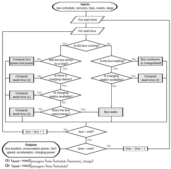
Figure 5.
Flow chart of the simulation of the bus fleet operation.
The process to compute the new status of a specific bus depends on the inputs. If the bus was previously being charged or stopped, it continues this way until its dwell time reaches zero. However, if the bus has to run at this time step (it was running previously or its dwell time at a bus stop is over), then its position and speed need to be assessed. When the bus starts running between two stops, its maximal speed and acceleration on the current segment are computed and its trapezoid-shaped speed profile is deduced. Then, the bus energy consumption is assessed for all the time steps. If the bus arrives at a stop at the next time step, its dwell time must be computed considering the required energy needed to reach the next charging station.
The dwell time is computed in two different ways depending on whether the bus is charging or not. The passengers boarding/alighting time is defined as the time taken by the passengers to board or alight from the bus. The minimal dwell time is defined as a necessary idle time for transportation reasons (e.g., to change driver). The theoretical dwell time is the difference between the time when the bus arrives at a stop and the theoretical time at when it is supposed to leave according to the timetable. In the case when the bus is not charging, dwell time is the maximal value among , , and . In the case when the bus is charging, the dwell time additionally depends on the time necessary to charge the battery to a sufficient level to travel to the next charging station . This case requires computing the distance to the next charging station and assuming an average consumption for the following trip.
Bus delay can be computed in two manners: charging delay and scheduling delay. The charging delay is the additional dwell time of a bus due to charging the bus battery, and the scheduling delay occurs because of other reasons which cause the bus to leave a bus stop late.
where is the computed dwell time, is the minimal dwell time at a stop, is the necessary dwell time for passengers’ boarding/alighting, is the theoretical dwell time before the next trip, is the time at which the bus arrives at the next stop, and is the theoretical arrival time at the next stop (according to the timetable).
4. Case Study
In this paper, the GTFS data are gathered for the city of Compiègne in France. The bus line “ARC EXPRESS”, which is 20 km long and composed of 12 bus stops, is chosen as the case study (see Figure 6). According to GTFS data, there are 11 routes and 36 trips used for providing transportation services over a day. The services of two buses were defined manually, so they matched the timetable. In order to realize all the trips defined on the timetable, the first bus “bus n°1” begins its service at 06:30 and ends it at 19:15. It performs 11 trips, including 2 between the bus depot and the line terminals. The second bus “bus n°2” operates from 06:10 to 18:50 and performs 15 trips. Both buses have long idle period in the middle of the day. The cumulative distance travelled by bus n°1 and bus n°2 are 149 km and 219 km, respectively. Concerning the speed profile between two bus stops, the acceleration is assumed to be constant at m/s [55]. Speed and acceleration limits are assumed as km/h and m/s, considering the need of passenger comfort [56].
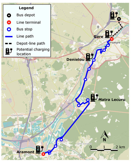
Figure 6.
Bus line ARC EXPRESS in Compiègne [57].
The 12m bus model from BYD has been chosen for this case study [58], and its characteristics are given in Table 2. This EB is equipped with a 422 kWh battery adding 2.8 tons (assuming 150 Wh/kg for lithium iron phosphate battery [1]) to the normal bus weight of 16.7 tons (total weight 19.5 tons). Average power values are assumed for the ventilation and the other auxiliaries [35]. The initial SoC of the EB battery is arbitrarily set to 90%.

Table 2.
Characteristics of the BYD-12 m bus and the PV panels.
Available charging powers are taken from the ABB’s chargers. Buses can be charged at the depot using a Combined Charging System plug with a power of 100 kW or 150 kW [59]. They can also be charged overnight at the depot with a pantograph at 50 kW [60]. Eventually, on-route charging at bus stops and terminals can be performed via ABB’s HVC-Opportunity charger at the power ratings of 150 kW, 300 kW, 450 kW, or 600 kW [60]. Scenarios described hereafter consider a power of 50 kW at the depot and 150 kW, 300 kW, 450 kW, and 600 kW for opportunity charging.
The number of boarding/alighting passengers is chosen arbitrarily, and the passenger flow is fixed for all routes of the same length. The number of passengers boarding/alighting is summarized in Table 3 for different lengths of bus sequence and one example for a bus route composed of 10 stops is displayed in Figure 7. The passage rate is assumed to be one passenger every four seconds [35]. An average passenger weight of 68 kg is considered. When computing the necessary energy to reach the next charging station, an arbitrary consumption of 1.3 kWh/km is chosen in order to keep a safety margin for considering the uncertainty on the future bus consumption.

Table 3.
Number of passengers boarding (B) and alighting (A) from the bus at each stop according to the length of the bus sequence.
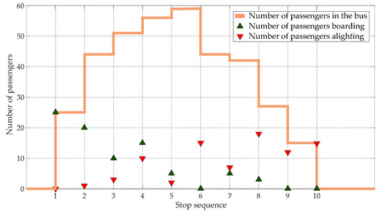
Figure 7.
Number of passengers boarding, alighting, and on the bus at each stop of route n°1.
Local PV production has been considered and compared to the energy needs of the buses. Irradiation and ambient temperature data have been gathered on the STELLA experimental platform of the Université de Technologie de Compiègne with a time step of 10 s. The PV power plant is assumed to operate without stationary storage. The electricity produced is primarily supplied to the bus charging stations and the surplus is injected into the utility grid. However, buses charge automatically when they reach an available charging station without a charging strategy. The objective is to determine the temporal adequacy between the PV production and the bus consumption according to the charging scenario. The data from two days, one in January and one in July, have been used. A 100-kWp PV installation, corresponding to a realistic surface of a bus depot, is considered in this example. The parameters of the PV panel are presented in Table 2. It is assumed in this paper that all charging stations and PV panels are connected to the same substation of the electric distribution network.
Simulations are performed and presented for three main scenarios with three additional sub-scenarios that differ only by their charging power. Charging scenarios are identified as follows:
- Scenario 1: two chargers at the depot;
- Scenarios 2 and 2bis: two chargers at the depot and a charger at “Gare” and “Aramont” line terminals;
- Scenarios 3, 3bis, and 3ter: chargers at the terminals “Gare” and “Aramont”, and bus stops “Denielou” and “Matra Lecuru”.
The number and location of charging stations are chosen arbitrarily. Charging powers at each location are presented in Table 4. The on-board battery capacity varies according to the scenarios from 70 kWh to 422 kWh. The simulations are performed over a day horizon with a two-second time step.

Table 4.
Location and power of charging stations in the different scenarios.
5. Results
5.1. Scenario 1—Charge at the Bus Depot
In this scenario, 2 buses with 422 kWh batteries realize their services over 1 day. A charging station is located at the bus depot with two 50 kW chargers. Figure 8 shows the cumulative distance travelled by each bus and the SoC of the buses battery. Horizontal portions represent dwell times at bus stops and line terminals. The dwell times at bus stops can be seen more easily on the zoomed-in Figure 8a as they are very short (around twenty seconds). SoC decreases over time as there are no charging points on the road. It can be noticed that, even with a 422 kWh battery, the battery SoC of bus n°2 with the highest daily consumption goes below 38%. As expected, buses are fully recharged at the depot during the night after completing daily service. The total energy consumption is 373 kWh—respectively, 155 kWh and 218 kWh for buses n°1 and 2—which represents an average consumption per travelled distance of 1.01 kWh/km.

Figure 8.
Travelled distance and battery SoC of buses n°1 (a) and n°2 (b)—scenario 1.
Figure 9 shows the total charging power at each time step, i.e., the sum of the charging power of all charging stations with the PV production on the 15 January and the 17 July. The charging starts at 18:50 when bus n°2 arrives to the depot. The charging power increases from 50 kW to 100 kW at 19:15 when both buses are at the depot for the night. The daily PV production is 108 kWh in January and 500 kWh in July, which makes it possible to balance the buses’ consumption only in July. PV energy could be stored in an additional stationary storage during the day and then used to charge the EBs’ batteries at night.
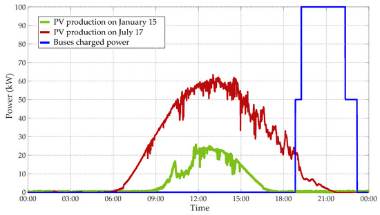
Figure 9.
Total charging power and PV production over time—scenario 1.
5.2. Scenario 2—Charge at the Line Terminals
In the second scenario, two additional 150 kW chargers are located at the line terminals Gare and Aramont (see Figure 6). The batteries’ SoCs of the buses are given in Figure 10. Buses recharge during their dwell time between consecutive trips without a delay. According to the number of times they pass through a charging station, bus n°1 charges approximately ten times and bus n°2 twelve times (cf. Section 4). The minimal values of the batteries’ SoCs are obtained at 79% for bus n°1 and 73% for bus n°2. This means that the on-board battery capacity can be reduced if charging stations are located at the line terminals. The total energy consumption is 373 kWh, which represents an average consumption per travelled distance of 1.01 kWh/km.

Figure 10.
Travelled distance and battery SoC of buses n°1 (a) and n°2 (b)—scenario 2.
It can be seen in Figure 11 that the two buses recharge during a short period at line terminals, usually not at the same time. However, the total charging power reaches 300 kW for 4 min at 18:36 when both buses are charging at bus terminals and 200 kW for 3 min at 19:02 when bus n°2 arrives at the terminal and bus n°1 is at the depot. The charging process occurs mainly during the day, when electricity is produced by PV panels. As for PV energy, 81 kWh are used directly to charge buses during the day, but additional stationary storage would increase the PV share during the day and allow the use of PV energy during the night.
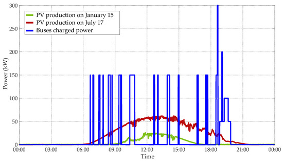
Figure 11.
Total charging power and PV production over time—scenario 2.
5.3. Scenario 3—Charge at Several Bus Stops
In scenario 3, the battery capacity of the bus is reduced to 70 kWh. Charging stations are located at line terminals Gare and Aramont, and at bus stops Denielou and Matra Lecuru. The charging power is limited to 150 kW. Therefore, there is a delay of 84 s in the dwell time due to the charging process at 09:49 and 10:08. Figure 12 shows the cumulative distance travelled by bus n°2 in scenario 1 and scenario 3. The black dotted line is shifted twice compared to the orange one. The reason why this delay does not spread is because the simulation authorizes the bus to accelerate (up to a limit) to reach the next bus stop on time, as explained in Section 3.2.2. Case studies with more frequent buses would probably show a more significant impact on the transport due to the waiting time of buses when they need to charge at a bus stop but the charging station is occupied. The delay could be avoided by increasing the on-board battery capacity, increasing the charging power, and/or adding new charging points on the road to reduce the required energy between two charges.
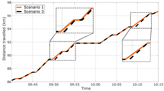
Figure 12.
Comparison between the distance travelled by bus n°2 in scenario 1 and scenario 3.
Figure 13 shows that the SoC of the 70 kWh battery of bus n°2 reaches 22.2% in scenario 3. This means that there is almost no security margin to ensure that the SoC will not fall below in case of a higher consumption. The total energy consumption is 337 kWh—respectively, 140 kWh and 197 kWh for buses n°1 and 2—which represents an average consumption per travelled distance of 0.91 kWh/km.

Figure 13.
Travelled distance and battery SoC of buses n°1 (a) and n°2 (b)—scenario 3.
Concerning the charging power, Figure 14 shows that most charges occur at different times with a power of 150 kW (the rated power of one charger). Rarely, 2 buses are charging at the same time, with a cumulative power of 300 kW when both buses are at bus stops (but not necessarily the same stop). The assumption here is that all chargers are connected to the same substation on the utility grid. Otherwise, the technical constraints would differ for each portion of the network where the chargers are located. Regarding PV energy, charging during the daylight at terminals and stops increases the PV self-consumption compared to scenarios 1 and 2. Additional storage would increase the PV benefits. Considering the reasonable amount of energy needed as the next charging station is close and the high charging power required due to the short duration of charges at bus stops, supercapacitors with a high power density could be used to store the solar energy but with an increased cost.
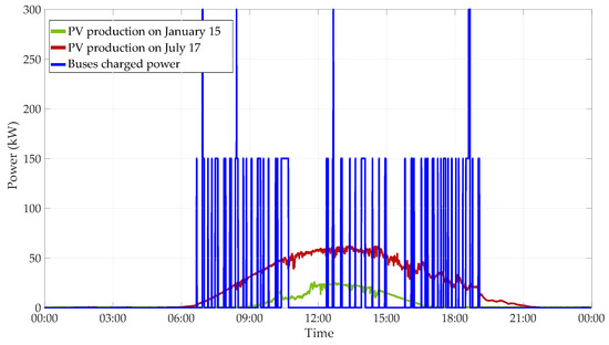
Figure 14.
Total charging power and PV production over time—scenario 3.
6. Discussion
In this section, performances of all the scenarios are summarized in Table 5 and the results are discussed focusing on the impacts on the utility grid in terms of energy and power with/without considering the presence of PV panels. First of all, the charging of EBs shows that the determined average bus consumption in terms of kWh/km is consistent with the literature data [4] which validates the presented model. However, it should be noted that there is a potential for further improvement of the presented model, through an analysis of the GTFS and Open Street Map data, by defining classes of roads according to the number of curves, intersections, and traffic lights. Additionally, the obtained energy consumption is 36 kWh (9.4%) less in scenario 3 (where a 70 kWh battery weighs 467 kg) compared to scenarios 1 and 2 (where a 422 kWh battery weighs 2.8 t). Therefore, the total energy consumption of the two buses during their daily operation decreases based on the capacity of on-board battery. Secondly, analysing the minimal SoC of the on-board battery allows assessing the adequacy between the capacity of the batteries and the charging scenario. For instance, in scenario 2, the minimal battery SoC of bus n°2 is determined at 73.3% which indicates that the battery is oversized or that it can be charged less frequently and/or at a lower power. On the other hand, in scenario 3 in which buses operate with a lower battery capacity, the SoC of bus n°2 decreases until it reaches 22.2%, which might increase charging time of the battery for next trip and cause delays in case of higher consumption. Lastly, the maximal charging power of the bus fleet is analysed for each scenario. The highest total power is determined at 1200 kW in scenario 3ter where the two buses charge their battery simultaneously on route. Although the peak power only lasts a few seconds/minutes, it can jeopardize the reliability of the utility grid due to severe changes in grid consumption in the case of a massive deployment of EBs. Utilization of PV energy can be considered low, which occurs because it is not able to charge the EBs’ batteries on the road. Therefore, the utilization of the hybrid energy system which is formed by PV panels and stationary storage is essential for increasing clean energy utilization for EBs. On the other hand, the PV panels might be integrated into the roof of the EBs in order to use produced PV power directly while moving on the road. However, in that case, the surrounding buildings around the road which EBs use to perform their services are required to be modelled in detail to consider the impact of the buildings’ shadows over the PV panels of the EB bus.

Table 5.
Performance indicators per scenario.
Concerning the utilization of local PV energy, simulation results show that only a small fraction of PV energy is directly supplied to EBs and the rest of the energy is injected back into the grid. The obtained self-consumption of the PV energy varies according to the scenarios as seen in Table 5. The highest utilization of the PV energy is obtained in scenario 2 (charging at terminals/depot) with 81 kWh, while the minimum is determined in scenario 1 (charging at depot) due to charging only at night. Moreover, it can be seen that the total energy production on January the 15th is lower than the buses’ energy consumption. On the other hand, the produced PV energy in July is sufficient to supply all buses’ consumption during the day if an additional stationary storage system is deployed.
Overall, this paper presents a methodology for modelling and analysing the consumption power of the EB fleet for various scenarios. The potential impacts of the EBs charging on the utility grid are discussed considering a local PV production without trying to minimize them via an optimization. However, results show that optimal planning and management are required for minimizing the grid impacts while maximizing the potential benefits. The main indicators that could be used as decision criteria for the implementation of a scenario are the EBs’ maximal charging power, grid supplied energy/power, and charging times. Based on the criteria, an optimal sizing of PV-storage-based charging infrastructure with an intelligent energy management algorithm can be developed for efficient public bus services that aims to increase renewable energy utilization by storing surplus production during the day and/or summer seasons and using it during low PV production times.
7. Conclusions
This study analyses the performance of various charging infrastructure placements. The proposed method considers a modelling of the bus network based on GTFS data and a sequential simulation of the bus operation. The method is applied to the operation of two buses on one bus line in Compiègne, France. Scenarios with charging stations at the depot, line terminals, and bus stops are compared. Results show the relevance of the method to estimate the impacts on both the transport delay and the power supplied from the grid. Charging at the depot implies having a larger on-board battery pack whereas on-route charging at bus stops and terminals helps reduce the battery capacity by 83%, and thus the bus consumption by 9.4% due to a reduction in the bus weight. However, on-route charging with a high power can have an impact on the utility grid, especially during the peaks of charging power. On the other hand, a lower charging power can generate some transport delay due to the slow charging process. The potential of a local PV production to reduce the impacts on the grid is shown. Nevertheless, the PV self-consumption remains very low during winter and PV energy cannot balance the buses consumption. During summer additional energy storage would increase PV benefits.
Future work will simulate the charging process with stationary storage and smarter charging strategies. Furthermore, charging stations and PV power plants will be positioned on the utility grid to model more realistically the impacts on each portion of the network. The operation of larger fleets will be simulated to underline different impacts. An annual time horizon will allow analysing the evolution of the solar irradiation, external temperature, passenger flow, and bus services according to the period of the year and thus to simulate more realistically the operation of buses. Eventually, several performance indicators will be implemented in an optimization algorithm for the sizing and management of PV-storage-based charging infrastructures of an EB network.
Author Contributions
Conceptualization, N.D. and B.C.; methodology, N.D.; software, N.D.; validation, N.D., B.C. and S.-K.C.-S.; formal analysis, N.D.; investigation, N.D.; resources, J.E. and S.-K.C.-S.; data curation, N.D.; writing—original draft preparation, N.D.; writing—review and editing, B.C., M.S., F.L. and J.E.; visualization, N.D.; supervision, M.S. and F.L.; project administration, M.S.; funding acquisition, M.S. All authors have read and agreed to the published version of the manuscript.
Funding
This research was funded by ADEME France, project T-IPV, grant number #2308D0002.
Institutional Review Board Statement
Not applicable.
Informed Consent Statement
Not applicable.
Data Availability Statement
Not applicable.
Acknowledgments
Authors would like to thank Amalie Alchami for her help to collect the irradiance and temperature data from the STELLA platform. They also thank all the bus operators who answered their questions in order to model more precisely the operation of buses.
Conflicts of Interest
The authors declare no conflict of interest.
References
- Avere-France. Guide Bus Électriques. Available online: https://www.avere-france.org/wp-content/uploads/site/documents/1632231132a3a1871eb36d22aa1acb6519aa46d6c7-GuidebuslectriquesAvere-Francevdef.pdf (accessed on 12 December 2022).
- UITP. ASSURED Clean Bus Report—An Overview of Clean Buses in Europe. Available online: https://cms.uitp.org/wp/wp-content/uploads/2022/04/ASSURED-Clean-Bus-Report-UITP-Final-v2.pdf (accessed on 12 December 2022).
- UITP. ZeEUS eBus Report #2—An Updated Overview of Electric Buses in Europe. Available online: https://zeeus.eu/uploads/publications/documents/zeeus-report2017-2018-final.pdf (accessed on 12 December 2022).
- Rodrigues, A.L.P.; Seixas, S.R.C. Battery-electric buses and their implementation barriers: Analysis and prospects for sustainability. Sustain. Energy Technol. Assess. 2022, 51, 101896. [Google Scholar] [CrossRef]
- Ji, J.; Bie, Y.; Zeng, Z.; Wang, L. Trip energy consumption estimation for electric buses. Commun. Transp. Res. 2022, 2, 100069. [Google Scholar] [CrossRef]
- He, Y.; Liu, Z.; Song, Z. Integrated charging infrastructure planning and charging scheduling for battery electric bus systems. Transp. Res. Part D Transp. Environ. 2022, 111, 103437. [Google Scholar] [CrossRef]
- TOSA. TOSA: Geneva’s Electrical Bus Innovation. Available online: https://www.intelligenttransport.com/transport-articles/71567/tosa-bus/ (accessed on 12 December 2022).
- Calstart. Zeroing in on ZEBs—2020 Edition. Available online: https://calstart.org/wp-content/uploads/2021/01/Zeroing_In_on_ZEBs_FINALREPORT_1262021.pdf (accessed on 12 December 2022).
- Perumal, S.S.G.; Lusby, R.M.; Larsen, J. Electric bus planning & scheduling: A review of related problems and methodologies. Eur. J. Oper. Res. 2022, 301, 395–413. [Google Scholar] [CrossRef]
- Manzolli, J.A.; Trovão, J.P.; Antunes, C.H. A review of electric bus vehicles research topics—Methods and trends. Renew. Sustain. Energy Rev. 2022, 159, 112211. [Google Scholar] [CrossRef]
- Boonraksa, T.; Boonraksa, P.; Marungsri, B. Optimal Capacitor Location and Sizing for Reducing the Power Loss on the Power Distribution Systems due to the Dynamic Load of the Electric Buses Charging System using the Artificial Bee Colony Algorithm. J. Electr. Eng. Technol. 2021, 16, 1821–1831. [Google Scholar] [CrossRef]
- Liu, K.; Gao, H.; Wang, Y.; Feng, T.; Li, C. Robust charging strategies for electric bus fleets under energy consumption uncertainty. Transp. Res. Part D Transp. Environ. 2022, 104, 103215. [Google Scholar] [CrossRef]
- Toniato, E.; Mehta, P.; Marinkovic, S.; Tiefenbeck, V. Peak load minimization of an e-bus depot: Impacts of user-set conditions in optimization algorithms. Energy Inform. 2021, 4, 23. [Google Scholar] [CrossRef]
- Gao, Z.; Lin, Z.; LaClair, T.J.; Liu, C.; Li, J.M.; Birky, A.K.; Ward, J. Battery capacity and recharging needs for electric buses in city transit service. Energy 2017, 122, 588–600. [Google Scholar] [CrossRef]
- Leone, C.; Sturaro, L.; Geroli, G.; Longo, M.; Yaici, W. Design and implementation of an electric skibus line in north Italy. Energies 2021, 14, 7925. [Google Scholar] [CrossRef]
- Hasan, M.M.; Avramis, N.; Ranta, M.; Saez-de Ibarra, A.; El Baghdadi, M.; Hegazy, O. Multi-Objective Energy Management and Charging Strategy for Electric Bus Fleets in Cities Using Various ECO Strategies. Sustainability 2021, 13, 7865. [Google Scholar] [CrossRef]
- Lotfi, M.; Pereira, P.; Paterakis, N.; Gabbar, H.; Catalao, J. Optimal Design of Electric Bus Transport Systems with Minimal Total Ownership Cost. IEEE Access 2020, 8, 119184–119199. [Google Scholar] [CrossRef]
- Kunith, A.; Mendelevitch, R.; Goehlich, D. Electrification of a city bus network—An optimization model for cost-effective placing of charging infrastructure and battery sizing of fast-charging electric bus systems. Int. J. Sustain. Transp. 2017, 11, 707–720. [Google Scholar] [CrossRef]
- Trocker, F.; Teichert, O.; Gallet, M.; Ongel, A.; Lienkamp, M. City-scale assessment of stationary energy storage supporting end-station fast charging for different bus-fleet electrification levels. J. Energy Storage 2020, 32, 101794. [Google Scholar] [CrossRef]
- Qin, N.; Gusrialdi, A.; Paul Brooker, R.; T-Raissi, A. Numerical analysis of electric bus fast charging strategies for demand charge reduction. Transp. Res. Part A Policy Pract. 2016, 94, 386–396. [Google Scholar] [CrossRef]
- Bie, Y.; Hao, M.; Guo, M. Optimal Electric Bus Scheduling Based on the Combination of All-Stop and Short-Turning Strategies. Sustainability 2021, 13, 1827. [Google Scholar] [CrossRef]
- Akaber, P.; Hughes, T.; Sobolev, S. MILP-based customer-oriented E-Fleet charging scheduling platform. IET Smart Grid 2021, 4, 215–223. [Google Scholar] [CrossRef]
- Lin, Y.; Zhang, K.; Shen, Z.J.M.; Ye, B.; Miao, L. Multistage large-scale charging station planning for electric buses considering transportation network and power grid. Transp. Res. Part C Emerg. Technol. 2019, 107, 423–443. [Google Scholar] [CrossRef]
- Tomizawa, Y.; Ihara, Y.; Kodama, Y.; Iino, Y.; Hayashi, Y.; Ikeda, O.; Yoshinaga, J. Multipurpose Charging Schedule Optimization Method for Electric Buses: Evaluation Using Real City Data. IEEE Access 2022, 10, 56067–56080. [Google Scholar] [CrossRef]
- Dalala, Z.; Al Banna, O.; Saadeh, O. The Feasibility and Environmental Impact of Sustainable Public Transportation: A PV Supplied Electric Bus Network. Appl. Sci. 2020, 10, 3987. [Google Scholar] [CrossRef]
- Arif, S.M.; Lie, T.T.; Seet, B.C.; Ahsan, S.M.; Khan, H.A. Plug-In Electric Bus Depot Charging with PV and ESS and Their Impact on LV Feeder. Energies 2020, 13, 2139. [Google Scholar] [CrossRef]
- Rafique, S.; Nizami, M.S.H.; Irshad, U.B.; Hossain, M.J.; Mukhopadhyay, S.C. A two-stage multi-objective stochastic optimization strategy to minimize cost for electric bus depot operators. J. Clean. Prod. 2022, 332, 129856. [Google Scholar] [CrossRef]
- Zhuang, P.; Liang, H. Stochastic Energy Management of Electric Bus Charging Stations with Renewable Energy Integration and B2G Capabilities. IEEE Trans. Sustain. Energy 2021, 12, 1206–1216. [Google Scholar] [CrossRef]
- Szcześniak, J.; Massier, T.; Gallet, M.; Sharma, A. Optimal Electric Bus Charging Scheduling for Local Balancing of Fluctuations in PV Generation. In Proceedings of the 2019 IEEE Innovative Smart Grid Technologies—Asia (ISGT Asia), Chengdu, China, 21–24 May 2019; pp. 2799–2804, ISSN 2378-8542. [Google Scholar] [CrossRef]
- Santos, T.; Lobato, K.; Rocha, J.; Tenedório, J.A. Modeling Photovoltaic Potential for Bus Shelters on a City-Scale: A Case Study in Lisbon. Appl. Sci. 2020, 10, 4801. [Google Scholar] [CrossRef]
- Islam, S.M.M.; Salema, A.A.; Lim, J.M.Y. Design and sizing of solar PV plant for an electric bus depot in Malaysia. E3S Web Conf. 2020, 160, 02003. [Google Scholar] [CrossRef]
- Ren, H.; Ma, Z.; Ming Lun Fong, A.; Sun, Y. Optimal deployment of distributed rooftop photovoltaic systems and batteries for achieving net-zero energy of electric bus transportation in high-density cities. Appl. Energy 2022, 319, 119274. [Google Scholar] [CrossRef]
- Ren, H.; Ma, Z.; Fai Norman Tse, C.; Sun, Y. Optimal control of solar-powered electric bus networks with improved renewable energy on-site consumption and reduced grid dependence. Appl. Energy 2022, 323, 119643. [Google Scholar] [CrossRef]
- Agglomération de la Région de Compiègne. Fiche Horaire Ligne ARC Express—MAJ November 2021. Available online: https://www.agglo-compiegne.fr/sites/default/files/2021-11/Fiche%20horaire%20ARCexpress%20%20MAJ%20nov%202021.pdf (accessed on 12 December 2022).
- Hjelkrem, O.A.; Lervåg, K.Y.; Babri, S.; Lu, C.; Södersten, C.J. A battery electric bus energy consumption model for strategic purposes: Validation of a proposed model structure with data from bus fleets in China and Norway. Transp. Res. Part D Transp. Environ. 2021, 94, 102804. [Google Scholar] [CrossRef]
- Li, X.; Wang, T.; Li, J.; Tian, Y.; Tian, J. Energy Consumption Estimation for Electric Buses Based on a Physical and Data-Driven Fusion Model. Energies 2022, 15, 4160. [Google Scholar] [CrossRef]
- Ma, X.; Miao, R.; Wu, X.; Liu, X. Examining influential factors on the energy consumption of electric and diesel buses: A data-driven analysis of large-scale public transit network in Beijing. Energy 2021, 216, 119196. [Google Scholar] [CrossRef]
- El-Taweel, N.A.; Zidan, A.; Farag, H.E.Z. Novel Electric Bus Energy Consumption Model Based on Probabilistic Synthetic Speed Profile Integrated with HVAC. IEEE Trans. Intell. Transp. Syst. 2021, 22, 1517–1531. [Google Scholar] [CrossRef]
- Abdelaty, H.; Mohamed, M. A framework for BEB energy prediction using low-resolution open-source data-driven model. Transp. Res. Part D Transp. Environ. 2022, 103, 103170. [Google Scholar] [CrossRef]
- Asamer, J.; Graser, A.; Heilmann, B.; Ruthmair, M. Sensitivity analysis for energy demand estimation of electric vehicles. Transp. Res. Part D Transp. Environ. 2016, 46, 182–199. [Google Scholar] [CrossRef]
- Jefferies, D.; Göhlich, D. A Comprehensive TCO Evaluation Method for Electric Bus Systems Based on Discrete-Event Simulation Including Bus Scheduling and Charging Infrastructure Optimisation. World Electr. Veh. J. 2020, 11, 56. [Google Scholar] [CrossRef]
- Göhlich, D.; Fay, T.A.; Jefferies, D.; Lauth, E.; Kunith, A.; Zhang, X. Design of urban electric bus systems. Des. Sci. 2018, 4, e15. [Google Scholar] [CrossRef]
- Lajunen, A.; Lipman, T. Lifecycle cost assessment and carbon dioxide emissions of diesel, natural gas, hybrid electric, fuel cell hybrid and electric transit buses. Energy 2016, 106, 329–342. [Google Scholar] [CrossRef]
- Cigarini, F.; Fay, T.A.; Artemenko, N.; Göhlich, D. Modeling and experimental investigation of thermal comfort and energy consumption in a battery electric bus. World Electr. Veh. J. 2021, 12, 7. [Google Scholar] [CrossRef]
- Vepsäläinen, J.; Kivekäs, K.; Otto, K.; Lajunen, A.; Tammi, K. Development and validation of energy demand uncertainty model for electric city buses. Transp. Res. Part D Transp. Environ. 2018, 63, 347–361. [Google Scholar] [CrossRef]
- Kivekäs, K.; Lajunen, A.; Baldi, F.; Vepsäläinen, J.; Tammi, K. Reducing the Energy Consumption of Electric Buses with Design Choices and Predictive Driving. IEEE Trans. Veh. Technol. 2019, 68, 11409–11419. [Google Scholar] [CrossRef]
- Kessler, L.; Bogenberger, K. Dynamic traffic information for electric vehicles as a basis for energy-efficient routing. Transp. Res. Procedia 2019, 37, 457–464. [Google Scholar] [CrossRef]
- Gis, W.; Kruczyński, S.; Taubert, S.; Wierzejski, A. Studies of energy use by electric buses in SORT tests. Combust. Engines 2017, 170, 135–138. [Google Scholar] [CrossRef]
- Kammuang-lue, N.; Boonjun, J. Energy consumption of battery electric bus simulated from international driving cycles compared to real-world driving cycle in Chiang Mai. Energy Rep. 2021, 7, 344–349. [Google Scholar] [CrossRef]
- Algin, V.; Goman, A.; Skorokhodov, A. Main operational factors determining the energy consumption of the urban electric bus: Schematization and modelling. Top. Issues Mech. Eng. Collect. Sci. Pap. 2019, 8, 185–194. [Google Scholar] [CrossRef]
- Sechilariu, M.; Locment, F. Urban DC Microgrid: Intelligent Control and Power Flow Optimization; Elsevier Butterworth-Heinemann: Amsterdam, The Netherlands; Paris, France, 2016. [Google Scholar]
- Google Developers. Google Transit|Static Transit|GTFS Reference. Available online: https://developers.google.com/transit/gtfs/reference (accessed on 12 December 2022).
- OpenStreetMap. Available online: https://www.openstreetmap.org/ (accessed on 12 December 2022).
- Open-Elevation API. Available online: https://open-elevation.com/ (accessed on 12 December 2022).
- Czogalla, O.; Jumar, U. Design and control of electric bus vehicle model for estimation of energy consumption. IFAC PapersOnLine 2019, 52, 59–64. [Google Scholar] [CrossRef]
- Fiori, C.; Montanino, M.; Nielsen, S.; Seredynski, M.; Viti, F. Microscopic energy consumption modelling of electric buses: Model development, calibration, and validation. Transp. Res. Part D Transp. Environ. 2021, 98, 102978. [Google Scholar] [CrossRef]
- Agglomération de la Région de Compiègne. Plan des Lignes périurbaines de l’ARC. Available online: https://www.agglo-compiegne.fr/sites/default/files/2021-07/Depliant%20PLAN%20TIC%20MAJ%20JUILLET%202021%20periurbain.pdf (accessed on 12 December 2022).
- BYD Europe. BYD 12m eBus Europe. Available online: https://bydeurope.com/pdp-bus-model-12 (accessed on 12 December 2022).
- Electric Vehicle Charging Infrastructure. ABB Electric Bus Charging Station|Electric Truck Charging. Available online: https://new.abb.com/ev-charging/depot-connector-charging (accessed on 12 December 2022).
- Electric Vehicle Charging Infrastructure. ABB Pantograph Bus|Pantograph Up. Available online: https://new.abb.com/ev-charging/pantograph-up (accessed on 12 December 2022).
Disclaimer/Publisher’s Note: The statements, opinions and data contained in all publications are solely those of the individual author(s) and contributor(s) and not of MDPI and/or the editor(s). MDPI and/or the editor(s) disclaim responsibility for any injury to people or property resulting from any ideas, methods, instructions or products referred to in the content. |
© 2023 by the authors. Licensee MDPI, Basel, Switzerland. This article is an open access article distributed under the terms and conditions of the Creative Commons Attribution (CC BY) license (https://creativecommons.org/licenses/by/4.0/).