To understand the physical process of thermal wave interference for the general case of multi-layered coating systems, it is necessary to take a closer look at known models for semi-infinite media and for the cases with
and
coatings. The mathematical notations and formulations in the next subsections can be found in [
4,
17,
18,
19].
2.1. Basics of Thermal Wave Generation
Thermal waves can be mathematically characterized as solutions of the heat diffusion equation. The heat source at the surface represents the boundary conditions, influences the surface temperature distribution, and determines the generation of waves. The most common type of excitation is a periodic, planar energy input with high-performance laser beams of a single specific excitation frequency, i.e., lock-in excitation.
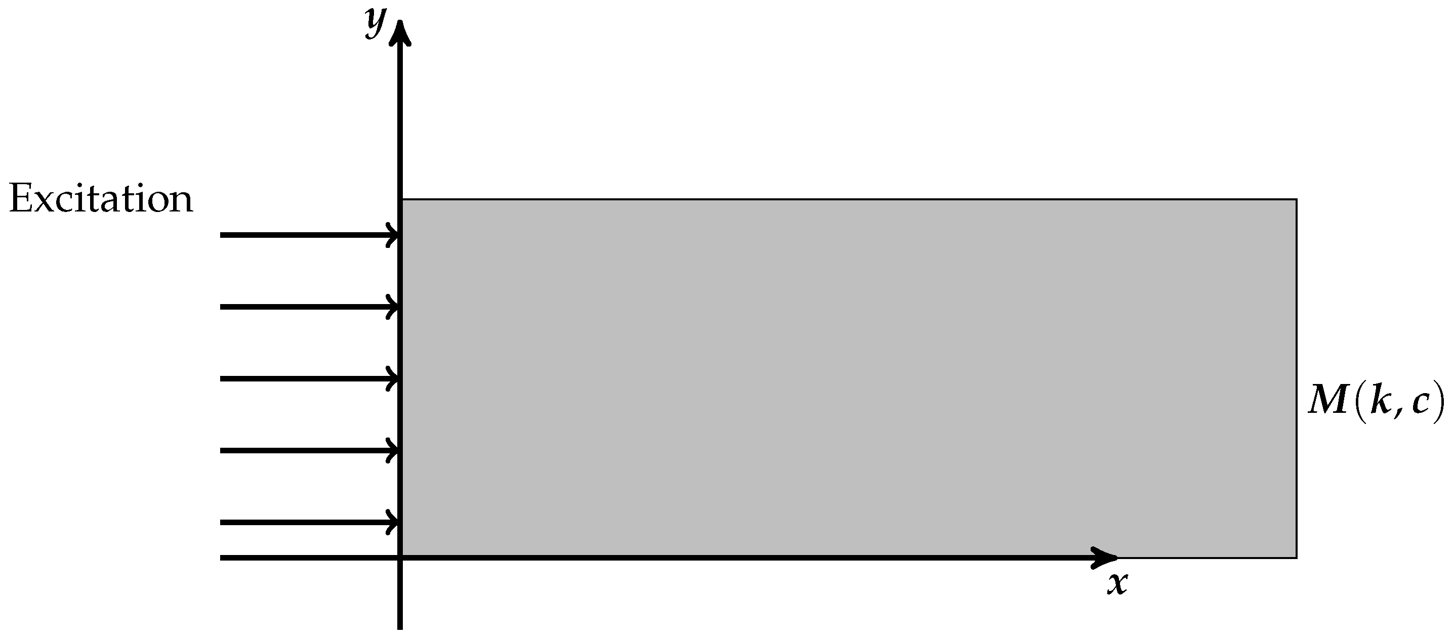
For the sake of simplicity, an isotropic homogeneous semi-infinite medium
M (that means an infinite extension of the medium in
x-direction) is considered, which is illustrated in
Figure 3.
Here, k denotes the thermal conductivity, and c denotes the volumetric heat capacity of the material M. The thermal diffusivity can then be calculated using and the thermal effusivity by .
It is assumed that the heated surface occupies the
-plane at
. To obtain the temperature distribution at the surface of the medium, the Fourier equation must be solved,
First, the boundary conditions need to be specified. The medium’s surface is excited with a plane harmonic; thus, temporal heating of modulation frequency
for some frequency
f and source intensity
. This leads to an excitation of the form
yielding the generation of thermal waves inside the medium.
Since the periodic thermal energy is subject to conduction into the solid, by using the appropriate rate equation, the boundary condition on the surface is given as
Here, dc means the
Direct Current and ac the
Alternating Current. The dc component will not be relevant in later applications and can be neglected. Applying a time-harmonic approach then yields
Plugging this in Equation (
1), one ends up with
Taking into account that
must be finite for
, one receives the solution of the boundary value problem (
1) and (
2) as
Using a multiplication with
and further simplifications, one obtains a more significant expression given as
where
is the so-called thermal diffusion length.
Hence, thermal waves are significantly dampened, where controls the penetration depth into the material. For small thermal diffusivity , the thermal waves do only slightly propagate into the interior of the material. In contrast, by decreasing the modulation frequency , a deeper penetration of the thermal waves into the material is obtained. This phenomenon is very useful in the photothermal measurement of layer thicknesses.
Furthermore, note that there occurs a progressive phase shift using
between the temperature at the surface and a point
x located at the propagating thermal wave in the material. Thus, at the surface
, an expressive phase difference of
between the excitation source and the resulting surface temperature can be observed.
2.2. Transmission and Reflection
If the irradiated object is not a semi-infinite medium but a composition of at least two materials
M and
(with thermal effusivities
e and
, respectively), the thermal wave travels through
M first towards
and, if the planar thermal wave propagation direction is perpendicular to its interface, the thermal reflection and transmission coefficients are
with
being the thermal refraction index, which characterizes the thermal contrast between the two media. If there is no thermal contrast, i.e., if
, it follows that
. In this case, there would be no significant reflection from this interface and, therefore, no contribution to thermal wave interference effects influencing the surface temperature. Thus, for a determination of coating layer thicknesses it is crucial to guarantee that the materials are distinguishable, i.e.,
.
In the following, whenever indices
are added to the reflection or transmission coefficient, this is assigned to the interface between the materials
and
. The direction of these coefficients has to be understood downwards, cf.
Figure 1. For the upward direction, a prime is added to the notation. For example,
The only exception regarding the direction is for
and
, where the top surface of first layer material
is exposed to air
, i.e.,
The reader is referred to [
4] for a more detailed derivation of the expressions above.
2.3. Basics of Thermal Wave Interference
In this subsection, the basics of thermal wave interference using an investigation of the cases of
and
coatings are discussed. Here, mathematical formulas are well established, cf. [
4,
18,
19]. For the convenience of the reader, the results are summarized before the insights are extended to multi-layered coating systems.
2.3.1. One-Layered Coatings on a Substrate
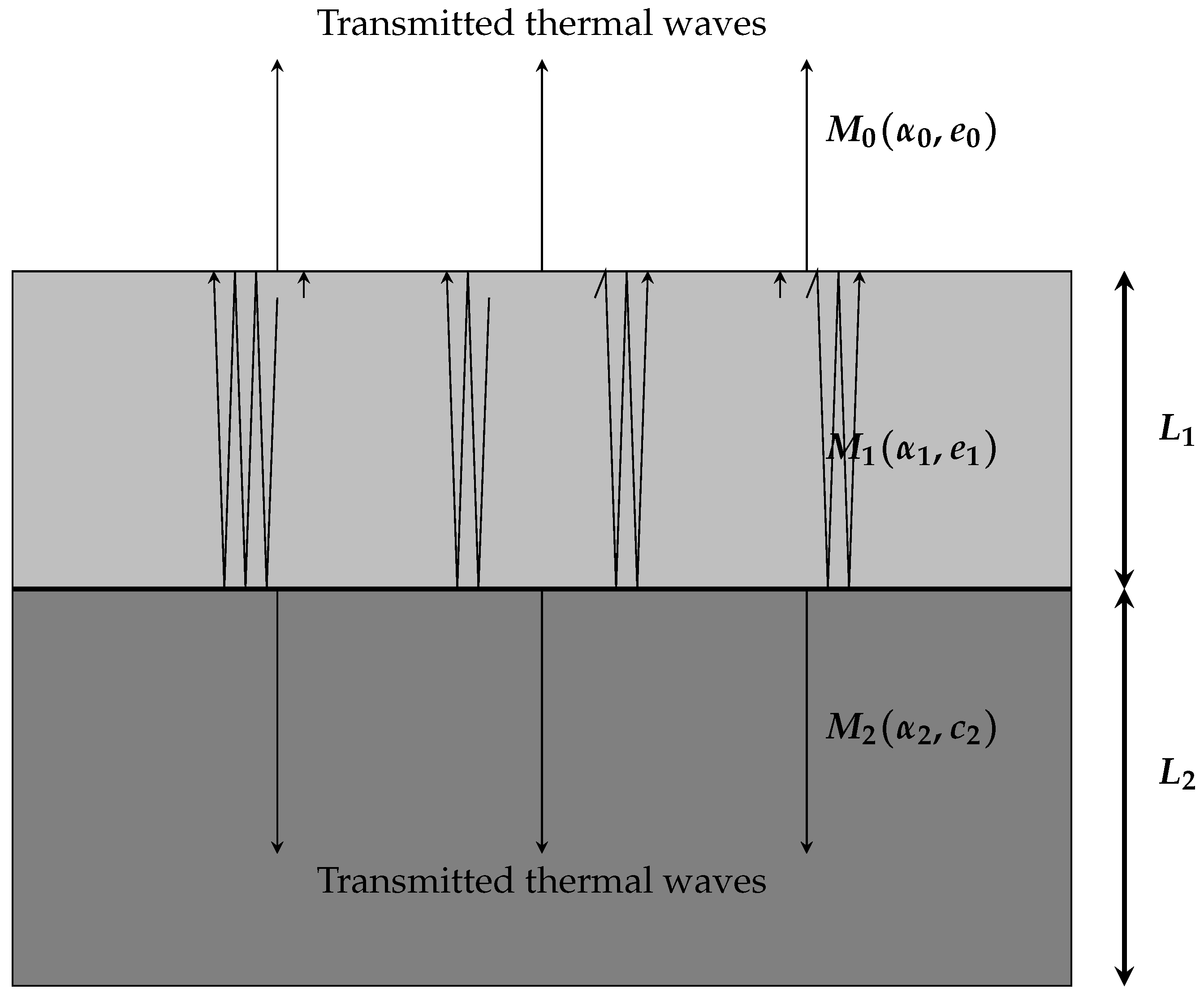
Consider the following system of two layers consisting of media
and
, as illustrated in
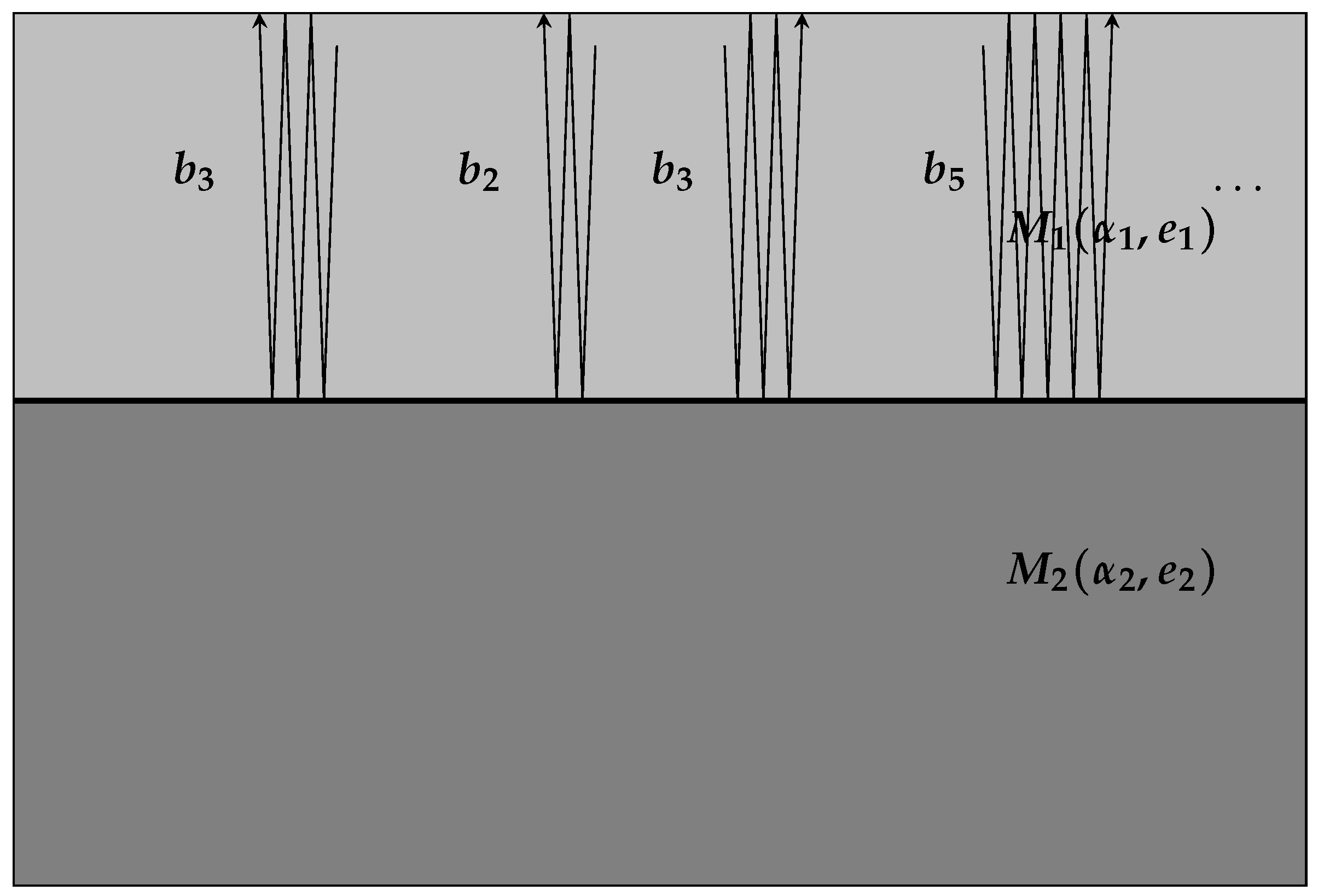
Figure 4.
Assume that both media and have homogeneous thermophysical properties and that has thickness and has thickness . Furthermore, assume that is thermally thick. That means that is significantly larger than the thermal diffusion length . This assumption is not unusual, as the substrate is often much thicker than the applied coating. This guarantees that the transmitted thermal waves into the substrate do not have an effect on the surface temperature because they can be neglected due to the large attenuation. Moreover, assume that the whole system is exposed to air (denoted by ). Suppose that the surface is illuminated by a plane, normal and periodic heating.
The single wave trains that are generated near the surface propagate towards the interface between the two media and back towards the surface of . When meeting any interfaces, the waves are partially reflected and transmitted. Thermal wave interference effects occur, meaning that the surface temperature at is a sum of all thermal wave trains. In general, when a thermal wave has traveled a distance the amplitude will be damped by , where is the complex wave number. Hence, for the first reflection order wave train in material , the thermal wave has a propagation path of length leading to an attenuation by . The following figures include sketches of thermal wave trains and give the impression that there is a lateral diffusion in the material itself. This, however, does not hold true since only one-dimensional propagation is present. The sketches serve only for graphic visualization.
Note that no bulk absorption of the absorbed radiation is considered in this article. This means that the photothermal effect provides surface heating only, i.e., thermal waves originate exclusively near . The presented references distinguish between the following two cases:
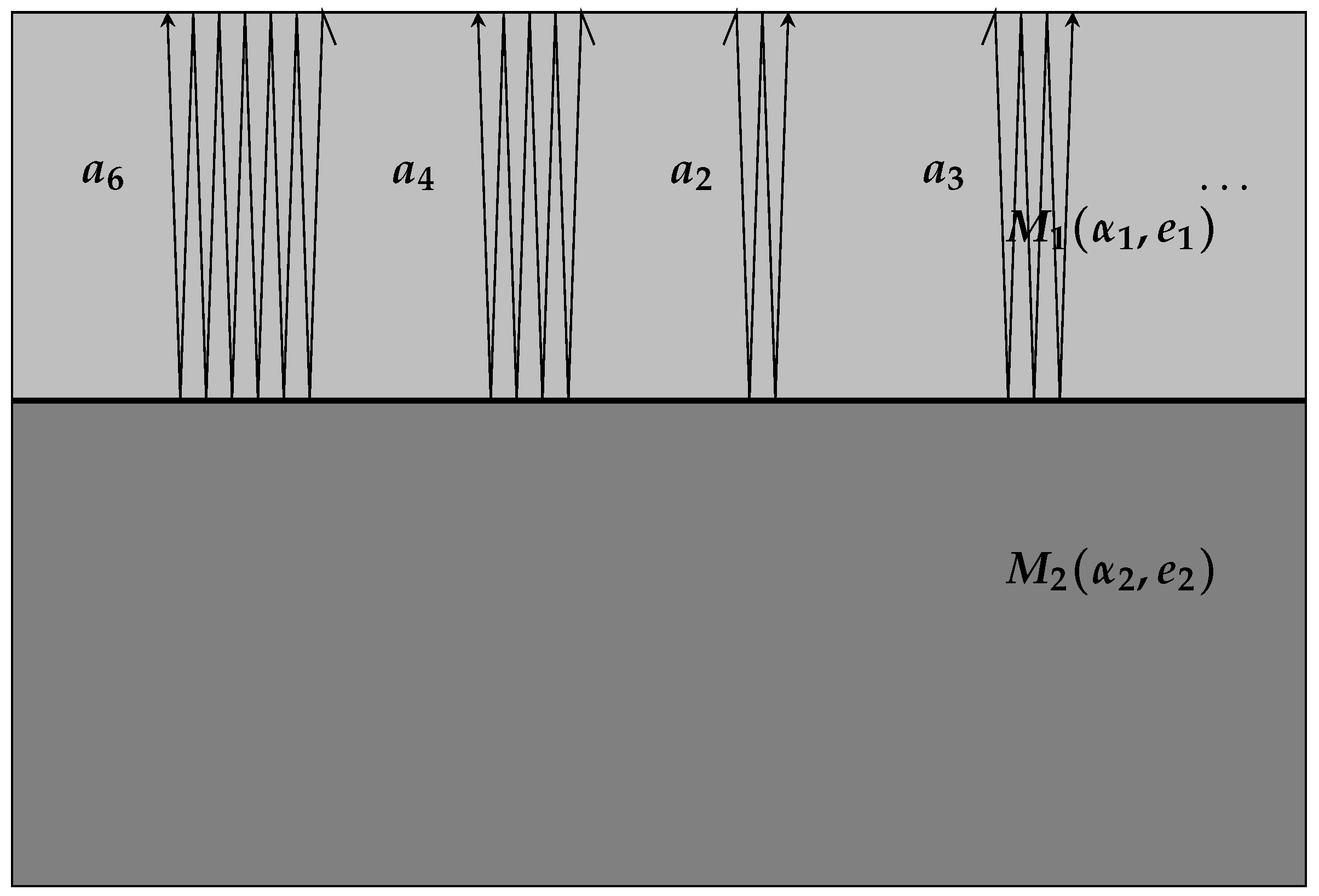
- (1)
Waves that are first reflected from the interface between
and
, see
Figure 5:
Let
denote the
nth reflection order wave and
the reflection coefficient at the interface between
and
(
and
, respectively). Furthermore, let
denote the transmission coefficients at the interface between
and
in the upward (downward) direction. Since the single wave trains are reflected at the interface “infinitely” often, one obtains the following series corresponding to the surface temperature:
where the geometric series formula is used, since
holds true.
- (2)
For waves that are first reflected from the interface between
and
, see
Figure 6, let
denote the
nth reflection order wave. Analogous to the first case, one obtains the following expression corresponding to the surface temperature fraction:
where the geometric series formula is used, since
holds true.
By summing up both series, one obtains the thermal wave interference expression at the surface:
This provides the following expression for the time-dependent temperature at the surface:
Note that the phase shift in this formula, given by
, is excluded and has the meaning of normalizing the temperature by subtracting an “infinitely” thick layer, cf. Equation (
6).
The wave vector
is complex and so is the temperature amplitude. It can be split into its real and imaginary parts providing an expression in polar coordinates. To this end, one sets
and calculate
and
Define
. Then the amplitude
is obtained using
as well as the phase angle
which provides an expression for the complex temperature amplitude at the surface in polar coordinates, i.e.,
The advantage is that the amplitude, as well as the phase, are measurable real valued expressions.
2.3.2. Two-Layered Coatings on a Substrate
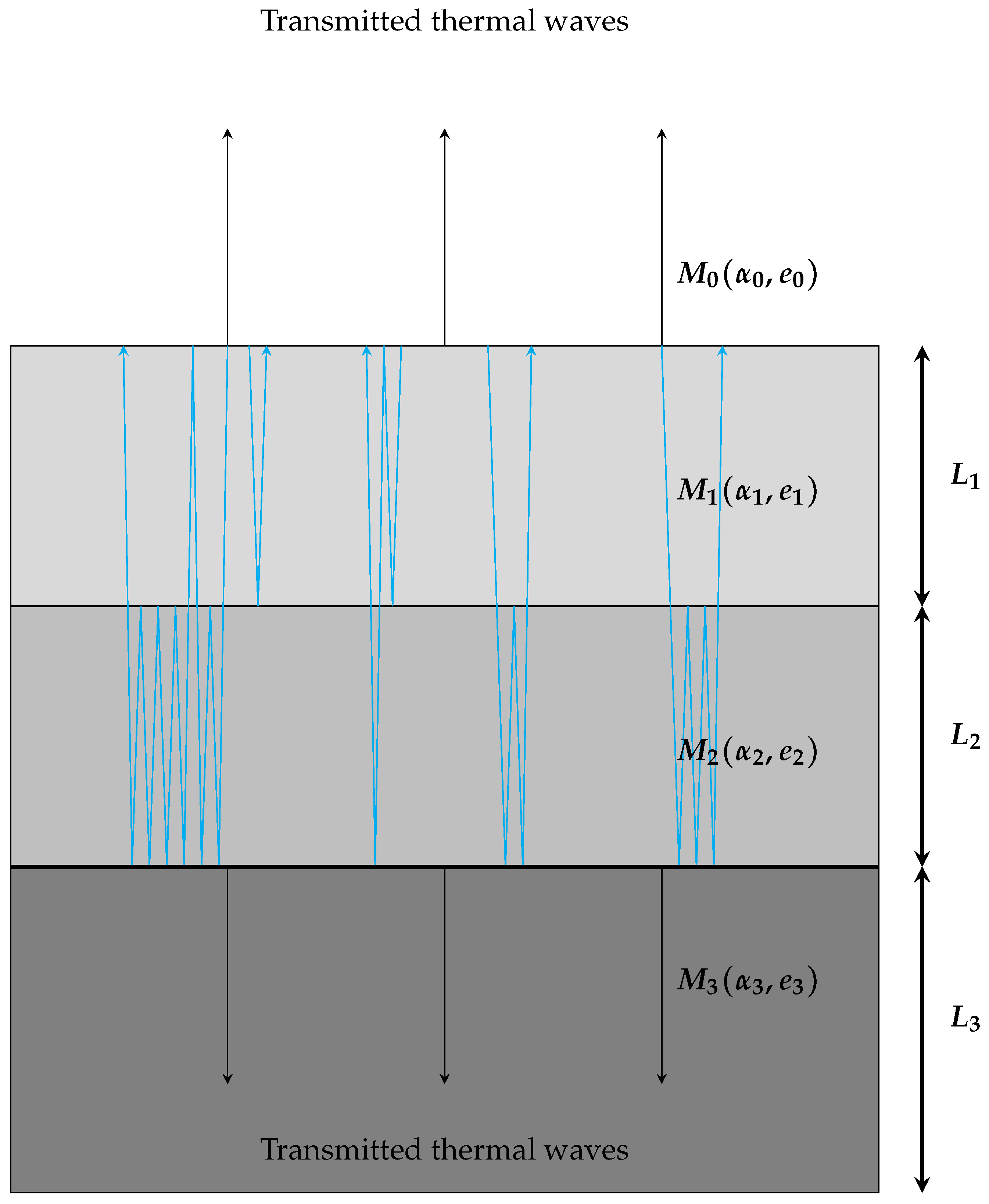
Next, consider the following system of three layers, –, having thicknesses –, where is assumed to be thermally thick.
Obviously, adding a second coating layer increases the complexity in which thermal wave trains can possibly propagate in the system, see, for example, the blue arrows in
Figure 7. The first interface for the case
was a coating-to-substrate interface, while for
the first interface is a coating-to-coating interface. Transmitted thermal waves can no longer be ignored, because the second layer is not thermally thick anymore, i.e., the reflections still contribute to the surface temperature significantly, although they have a longer propagation path. A very elegant way of summarizing all possible wave trains is done by replacing a complex-valued effective reflection coefficient
for the real-valued reflection coefficient
from Equation (
11), cf. [
4,
19].
Again, by introducing a new layer, the reflection process expands after passing the interface between
and
and appear at a lower level, too. Thus, interference effects occur in the new layer with material
as well. This implies that the reflection coefficient
is not sufficient to describe the whole process anymore, so it is necessary to change the expression in
analogously to the derivation in Equation (
9) as
Here, ( denotes the transmission coefficients in a downward (upward) direction at the – interface. Using (), one denotes the reflection coefficients at the same interface, where the thermal wave train stays in (). Analogously, is the reflection coefficient for thermal waves in that stay in .
Therefore, because of
, the geometric series formula can be used again, since
. Note that
which effectively represents the case
again, if the second coating layer would be infinitely thick (or at least thermally thick).
The quantity
is called the effective reflection coefficient. Since the thermal interference processes are the same in the first layer as discussed before, one ends up with the following surface temperature for
:
Once again, this expression provides a term for the amplitude,
as well as for the phase angle,
yielding
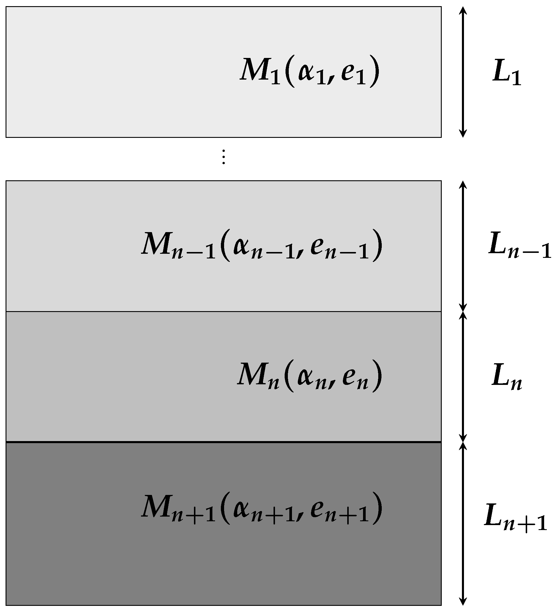
2.4. Generalization to Multi-Layered Coating Systems
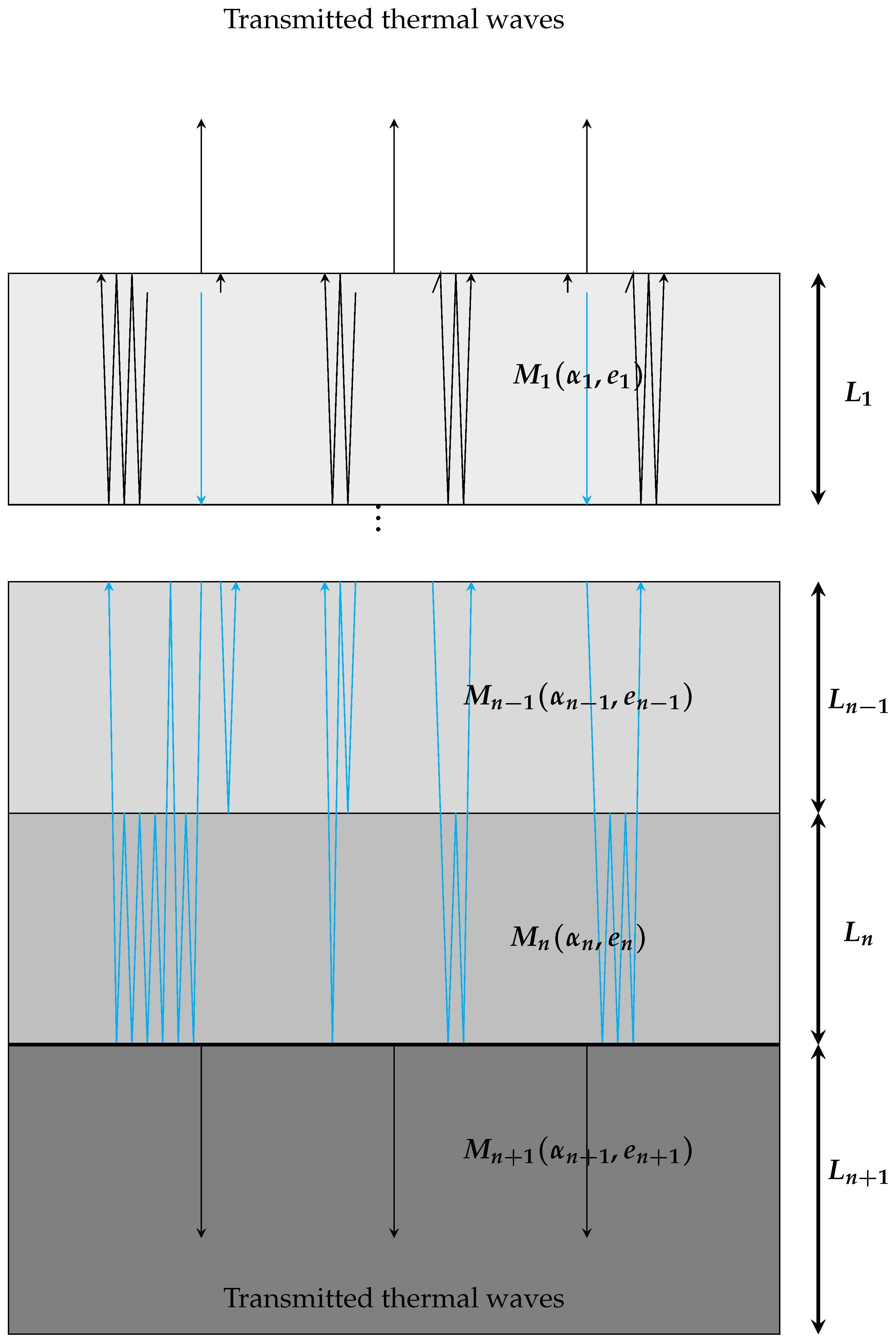
The subject of the investigations is to make use of the insights outlined before and generalize Formula (
17) for a multi-layered coating system; see
Figure 8. Consider the following system consisting of
layers of coatings with material
–
having thicknesses
–
on a thermally thick substrate material
.
For
, the idea was to look at the last reflection coefficient from the case
and, since a new layer is added, replace it by some effective reflection coefficient
including all potential wave trains that are apparent in the new system. This principle can be extended further, which leads to nested effective reflection coefficients, i.e., one defines
recursively with
Although the generalized formula for the surface temperature of multi-layered coating systems looks as for
, i.e.,
the effective reflection coefficient
now contains all the significant information about the coating system, such as the layer thicknesses
, the thermal diffusivities
, and the thermal effusivities
. Note that
and
are not of any interest because the substrate is thermally thick, but
is needed for the calculation of
.

