
Extended-Reach Drilling (ERD)—The Main Problems and Current Achievements


Abstract
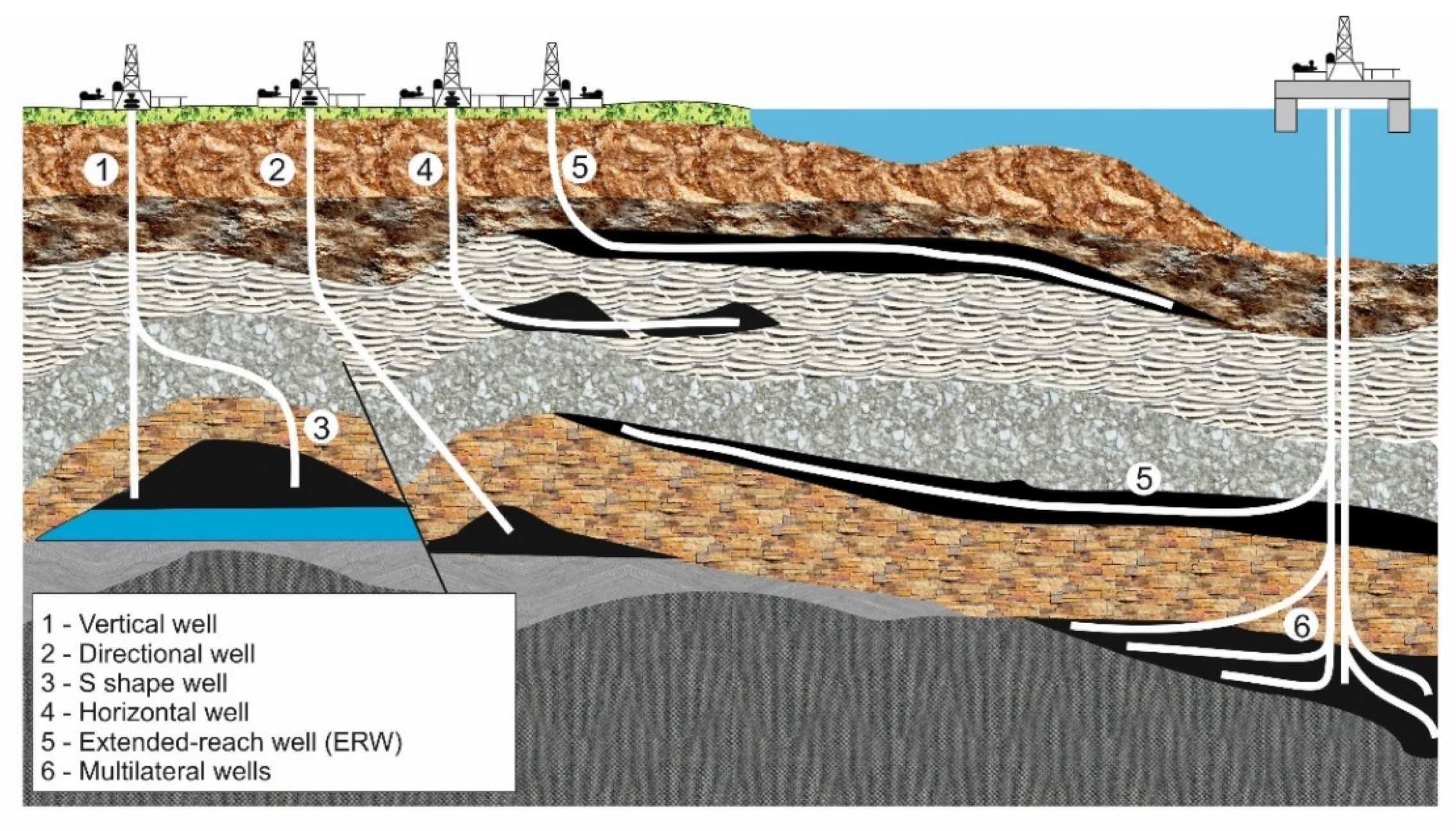
1. Introduction
2. Problems with ERD
3. Drilling Fluids for Extended-Reach Wells
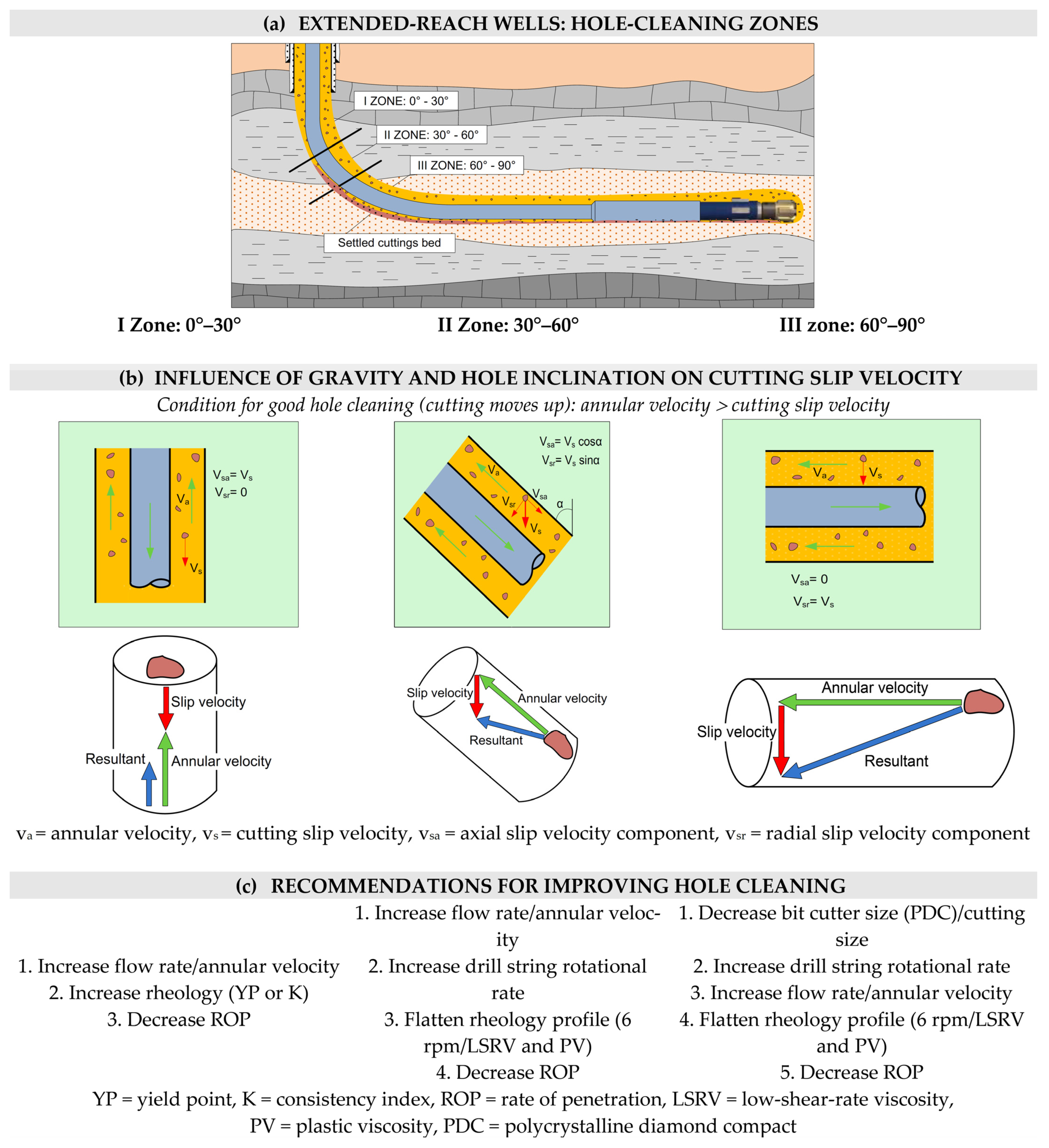
3.1. Hole Cleaning
3.2. Torque and Drag
3.3. Equivalent Circulating Density
3.4. Barite Sag
3.5. Drilling Fluid Selection
4. Analysis of the Presented Case History Data
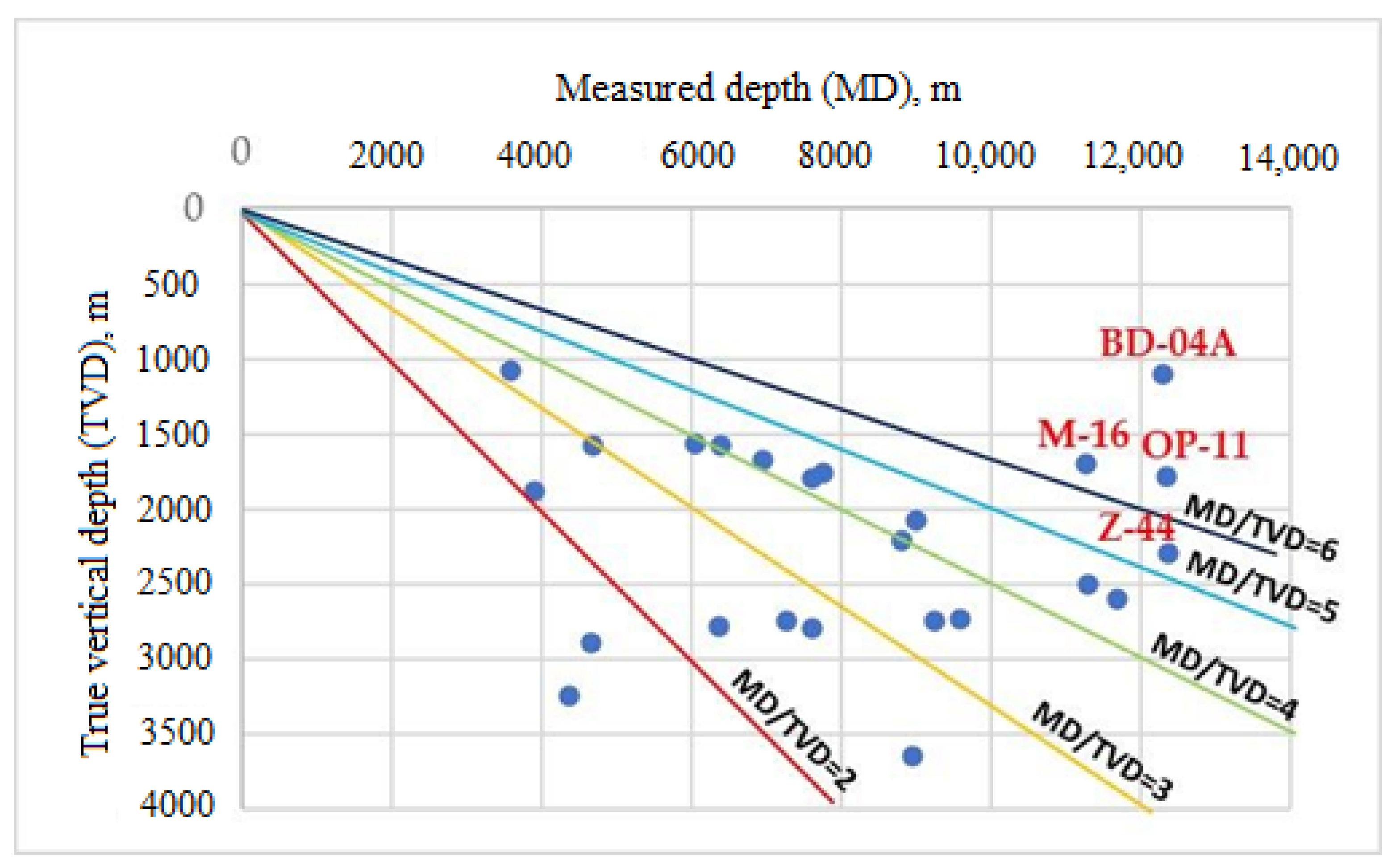
4.1. Well Trajectory
4.2. Well Construction
4.3. Drilling Fluid
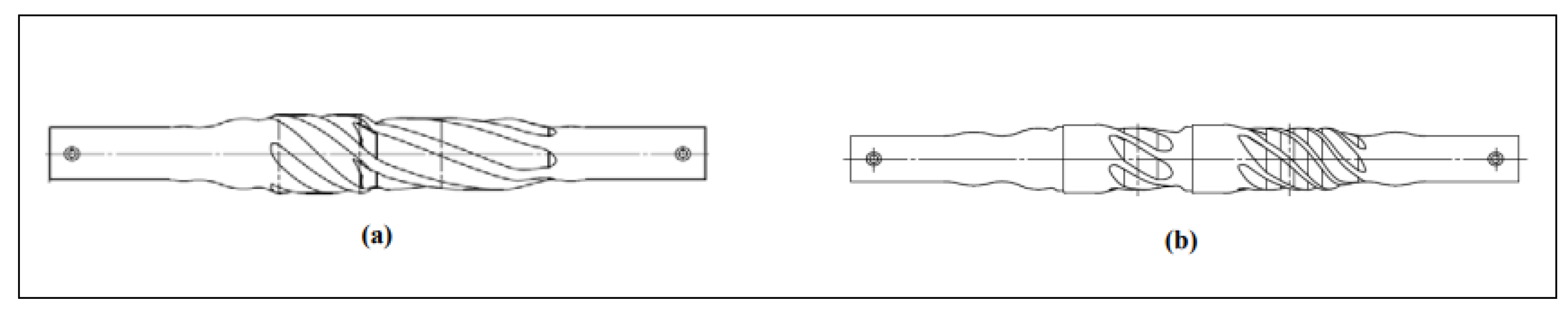
4.4. Used Directional Drilling Tools
4.5. Problems and Solutions during Drilling and Well Completion
5. Conclusions
Author Contributions
Funding
Institutional Review Board Statement
Informed Consent Statement
Data Availability Statement
Conflicts of Interest
References
- Carden, R.S.; Grace, R.D. Horizontal and Directional Drilling; PetroSkills OGCI: Tulsa, OK, USA, 2007. [Google Scholar]
- Gaurina-Međimurec, N.; Pašić, B.; Mijić, P. Oil and Gas New Drilling Technologies. Annu. Croat. Acad. Tech. Sci. 2016, 2017, 101–128. [Google Scholar]
- E-Tech International/Powers Engineering. Comprehensive Extended Reach Drilling (ERD) Study for Block 56. DRAFT E-Tech International/Powers Engineering, 4452 Park Blvd., Suite 209. San Diego, California 92116, August 17, 2005. Available online: https://static1.squarespace.com/static/52d71403e4b06286127a1d48/t/53237d7ee4b0e6df3fc7bce9/1394834814315/081705TORERDBlock56.pdf (accessed on 17 February 2023).
- Tveitdal, T. Torque and Drag Analysis of North Sea Well Using New 3D Model. Master’s Thesis, University of Stavanger, Stavanger, Norway, June 2011. [Google Scholar]
- Bennetzen, B.; Fuller, J.; Isevcon, E.; Krepp, T.; Meehan, R.; Mohammed, N.; Poupeau, J.-F.; Sonowal, K. Oil Filed Review Autumn 2010; Schlumburger: Paris, France, 2010; Volume 22, pp. 4–15. [Google Scholar]
- Agbaji, A.L. Development of an Algorithm to Analyze the Interrelationship Among Five Elements Involved in the Planning, Design and Drilling of Extended Reach and Complex Wells. Master’s Thesis, The Pennsylvania State University, The Graduate School, Department of Energy and Mineral Engineering, University Park, PA, USA, May 2009. [Google Scholar]
- Chen, X.; Gao, D. The Maximum-Allowable Well Depth While Performing Ultra-Extended-Reach Drilling From Shallow Water to Deepwater Target. SPE J. 2018, 23, 224–236. [Google Scholar] [CrossRef]
- Conran, G. Overview: Horizontal and Complex Trajectory Wells (November 2007). J. Pet. Technol. 2007, 59, 64. [Google Scholar] [CrossRef]
- Yeung, J.; Li, J.; Lee, J.; Guo, X. Evaluation of Lubricants Performance for Coiled Tubing Application in Extended Reach Well. In Proceedings of the SPE/ICoTA Coiled Tubing and Well Intervention Conference and Exhibition, Houston, TX, USA, 21–22 March 2017. SPE-184810-MS. [Google Scholar] [CrossRef]
- Li, X.; Gao, D.; Lu, B.; Zeng, Y.; Ding, S.; Zhou, S. A Prediction Model of the Shortest Drilling Time for Horizontal Section in Extended Reach Well. J. Pet. Sci. Eng. 2019, 182, 106319. [Google Scholar] [CrossRef]
- Chen, X.; Jin Yang, J.; Gao, D.; Hong, Y.; Zou, Y.; Du, X. Unlocking the deepwater natural gas hydrate’s commercial potential with extended reach wells from shallow water: Review and an innovative method. Renew. Sustain. Energy Rev. 2020, 134, 110388. [Google Scholar] [CrossRef]
- Gupta, A. Planning and Identifying Best Technologies for ERD Wells. In Proceedings of the SPE/IADC 102116, SPE/IADC Indian Drilling Technology Conference and Exhibition, Mumbai, India, 16–18 October 2006; pp. 1–6. [Google Scholar]
- Klotz, C.; Bond, P.R.; Wassermann, I.; Priegnitz, S. A New Mud Pulse Telemetry System for Enhanced MWD/LWD Applications. In Proceedings of the IADC/SPE 112683, IADC/SPE Drilling Conference, Orlando, FL, USA, 4–6 March 2008. [Google Scholar]
- Chen, J.; Li, S.; Macmillan, C.; Cortes, G.; Wood, D. Long Range Electromagnetic Telemetry Using an Innovative Casing Antenna System. In Proceedings of the SPE-174821-MS SPE, Annual Technical Conference and Exhibition, Dallas, TX, USA, 28–30 September 2015. [Google Scholar]
- Reeves, M.E.; Camwell, P.L.; Mcrory, J. High Speed Acoustic Telemetry Network Enables Real-Time Along String Measurements, Greatly Reducing Drilling Risk. In Proceedings of the SPE 145566, SPE Offshore Europe Oil and gas Conference and Exhibition, Aberdeen, UK, 6–8 September 2011. [Google Scholar]
- Reeves, M.; Macpherson, J.D.; Zaeper, R.; Bert, D.R.; Shursen, J.; Armagost, W.K.; Paxton, D.S.; Hernandez, M. High Speed Drill String Telemetry Network Enables New Real Time Drilling and Measurement Technologies. In Proceedings of the IADC/SPE 99134, IADC/SPE Drilling Conference, Miami, FL, USA, 21–23 February 2006. [Google Scholar]
- Ljubetić, J. Possibility of A Two Way Communication with Bottom Hole Assembly by Implementing Different Telemetry Systems. Master’s Thesis, University of Zagreb, Zagreb, Croatia, June 2020. [Google Scholar]
- Cameron, C. Drilling Fluids Design and Management for Extended Reach Drilling. In Proceedings of the IADC/SPE Middle East Drilling Technology Conference, Bahrain, 22–24 October 2001. [Google Scholar] [CrossRef]
- Morrison, A.; Serov, N.; Ahmed, F. Completing Ultra Extended-Reach Wells: Overcoming the Torque and Drag Constraints of Brine. In Proceedings of the Abu Dhabi International Petroleum Exhibition & Conference, Abu Dhabi, United Arab Emirates, 11–14 November 2019. [Google Scholar] [CrossRef]
- Walker, S.; Li, J. The Effects of Particle Size, Fluid Rheology, and Pipe Eccentricity on Cuttings Transport. In Proceedings of the SPE/ICoTA Coiled Tubing Roundtable, Houston, TX, USA, 5–6 April 2000. [Google Scholar] [CrossRef]
- Zou, L.; Patel, M.H.; Han, G. A New Computer Package for Simulating Cuttings Transport and Predicting Hole Cleaning in Deviated and Horizontal Wells. In Proceedings of the SPE International Oil and Gas Conference and Exhibition, Beijing, China, 7–10 November 2000. [Google Scholar] [CrossRef]
- Masuda, Y.; Doan, Q.; Oguztoreli, M.; Naganawa, S.; Yonezawa, T.; Kobayashi, A.; Kamp, A. Critical Cuttings Transport Velocity in Inclined Annulus: Experimental Studies and Numerical Simulation. In Proceedings of the SPE SPE/CIM International Conference on Horizontal Well Technology, Calgary, AB, Canada, 6–8 November 2000. [Google Scholar] [CrossRef]
- Ozbayoglu, M.E.; Miska, S.Z.; Reed, T.; Takach, N. Analysis of the Effects of Major Drilling Parameters on Cuttings Transport Efficiency for High-Angle Wells in Coiled Tubing Drilling Operations. In Proceedings of the SPE/ICoTA Coiled Tubing Conference and Exhibition, Houston, TX, USA, 23–24 March 2004. [Google Scholar] [CrossRef]
- Costa, S.S.; Stuckenbruck, S.; Fontoura, S.A.B.; Martins, A.L. Simulation of Transient Cuttings Transportation and ECD in Wellbore Drilling. In Proceedings of the 2008 SPE Europec/EAGE Conference and Exhibition, Rome, Italy, 9–12 June 2008. [Google Scholar] [CrossRef]
- Cheng, R.; Wang, R. A Three-Segment Hydraulic Model for Annular Cuttings Transport with Foam in Horizontal Drilling. J. Hydrodyn. 2008, 20, 67–73. [Google Scholar] [CrossRef]
- Mohammadsalehi, M.; Malekzadeh, N. Optimization of hole Cleaning and cuttings Removal in Vertical, Deviated and Horizontal Wells. In Proceedings of the SPE Asia Pacific Oil and Gas Conference and Exhibition, Jakarta, Indonesia, 20–22 September 2011. [Google Scholar] [CrossRef]
- Ogunrinde, J.O.; Dosunmu, A. Hydraulic Optimization for Efficient Hole Cleaning in Deviated and Horizontal Wells. In Proceedings of the 2012 SPE Nigerian Annual International Conference and Exhibition, Abuja, Nigeria, 6–8 August 2012. [Google Scholar] [CrossRef]
- Cayeux, E.; Mesagan, T.; Tanripada, S.; Zidan, M.; Fjelde, K.K. Real-Time Evaluation of Hole-Cleaning Conditions with a Transient Cuttings-Transport Model. SPE Drill. Complet. 2014, 29, 5–21. [Google Scholar] [CrossRef]
- Ozbayoglu, E.M.; Erge, O.; Ozbayoglu, M.A. Predicting the pressure losses while the drillstring is buckled and rotating using artificial intelligence methods. J. Nat. Gas Sci. Eng. 2018, 56, 72–80. [Google Scholar] [CrossRef]
- Gul, S.; Johnson, M.D.; Karimi Vajargah, A.; Ma, Z.; Hoxha, B.B.; van Oort, E. A data driven approach to predict frictional pressure losses in polymer-based fluids. In Proceedings of the SPE/IADC Drilling International Conference and Exhibition, The Hague, The Netherlands, 5–7 March 2019. [Google Scholar] [CrossRef]
- Saini, G.S.; Ashok, P.; van Oort, E. Predictive Action Planning for Hole Cleaning Optimization and Stuck Pipe Prevention Using Digital Twinning and Reinforcement Learning. In Proceedings of the SPE-199548-MS. IADC/SPE International Drilling Conference and Exhibition, Galveston, TX, USA, 3–5 March 2020. [Google Scholar] [CrossRef]
- Shirangi, M.G.; Ettehadi, R.; Aragall, R.; Furlong, E.; May, R.; Dahl, T.; Samnejad, M.; Thompson, C. Digital Twins for Drilling Fluids: Advances and Opportunities. In Proceedings of the SPE 199681-MS. IADC/SPE International Drilling Conference and Exhibition, Galveston, TX, USA, 3–5 March 2020. [Google Scholar] [CrossRef]
- Gul, S. Machine Learning Applications In Drilling Fluid Engineering: A Review. In Proceedings of the ASME 2021 40th International Conference on Ocean, Offshore and Arctic Engineering OMAE2021, OMAE2021-63094, Virtual Online, 21–30 June 2021. [Google Scholar]
- Cao, L.; Sun, J.; Zhang, B.; Lu, N.; Xu, Y. Sensitivity analysis of the temperature profile changing law in the production string of a high-pressure high-temperature gas well considering the coupling relation among the gas flow friction, gas properties, temperature, and pressure. Front. Phys. 2022, 10, 1050229. [Google Scholar] [CrossRef]
- Chima, J.; Umarin, I.; Kunhiveetil, D.; Otaif, H.; Al Dabyah, A.; Bilal, Z. Proper Planning Supported by Latest Technology Leads to Drilling the Longest 8.5-in Section in an Extended-Reach Well: Case Study. In Proceedings of the Offshore Technology Conference Asia, Kuala Lumpur, Malaysia, 22–25 March 2016. [Google Scholar] [CrossRef]
- Chamat Burgos, E.; Peñaranda, J.; Gonzalez, K.; Trejo, E.; Meneses, M.; Rosales, A.; Martinez, J. Shallow Horizontal Drilling Meets with Very Extended Reach Drilling in the Venezuelan Faja. In Proceedings of the SPE Latin America and Caribbean Petroleum Engineering Conference, Maracaibo, Venezuela, 21–23 May 2014. [Google Scholar] [CrossRef]
- Legarth, B.; Lehner, J.; Okibe, H.; Koinkar, V.; Mammod, Z. Changing the Game from Steel to Aluminum Drill Pipe: Results from Full String Aluminum Alloy Drill Pipe Deployment to Enhance Extended Reach Drilling Performance. In Proceedings of the SPE/IADC Drilling Conference and Exhibition, London, UK, 17–19 March 2015. [Google Scholar] [CrossRef]
- Glebov, E.; Shokarev, I.; Gulov, A.; Zhludov, A.; Dymov, S.; Dobrokhleb, P.; Kretsul, V.; Zadvornov, D.; Kondarev, V.; Fedotov, A. Yurkharovskoye Extended Reach Drilling Campaign Resulted in the Successful Completion of Record Multilateral Well. In Proceedings of the SPE Russian Petroleum Technology Conference, Moscow, Russia, 26–28 October 2015. [Google Scholar] [CrossRef]
- Wilson, A. Innovative Tool Improves Hole-Cleaning Efficiency in Extended-Reach Wells. J. Pet. Technol. 2016, 68, 80–82. [Google Scholar] [CrossRef]
- Naegel, M.; Pradie, E.; Delahaye, T.; Mabile, C.; Roussiaux, G. Cuttings Flow Meters Monitor Hole Cleaning in Extended Reach Wells. In Proceedings of the European Petroleum Conference, The Hague, The Netherlands, 20–22 October 1998. [Google Scholar] [CrossRef]
- Mason, C.J.; Allen, F.M.; Ramirez, A.A.; Wolfson, L.; Tapper, R. Casing Running Milestones for Extended-Reach Wells. In Proceedings of the SPE/IADC Drilling Conference, Amsterdam, The Netherlands, 9–11 March 1999. [Google Scholar] [CrossRef]
- Trahan, K.; MacDonald, J.; Webster, S.; Colin, M. A Proven Liner Flotation Method for Extended-Reach Wells. In Proceedings of the IADC/SPE Drilling Conference, New Orleans, LA, USA, 23–25 February 2000. [Google Scholar] [CrossRef]
- Cameron, C.; Helmy, H.; Mohamed, H. Fibrous LCM Sweeps Enhance Hole Cleaning and ROP on Extended Reach Well in Abu Dhabi. In Proceedings of the Middle East Oil Show, Bahrain, 5–8 April 2003. [Google Scholar] [CrossRef]
- Elsborg, C.C.; Power, A.K.; Schuberth, P.C. Hibernia Record Well Breaks Extended Reach Drilling and Completion Envelope. In Proceedings of the SPE/IADC Drilling Conference, Amsterdam, The Netherlands, 23–25 February 2005. [Google Scholar] [CrossRef]
- Walker, M.W. Pushing the Extended Reach Envelope at Sakhalin: An Operator’s Experience Drilling a Record Reach Well. In Proceedings of the IADC/SPE Drilling Conference and Exhibition, San Diego, CA, USA, 6–8 March 2012. [Google Scholar] [CrossRef]
- Walker, M.W.; Veselka, A.J.; Shane, A.H. Increasing Sakhalin Extended Reach Drilling and Completion Capability. In Proceedings of the SPE/IADC Drilling Conference and Exhibition, Amsterdam, The Netherlands, 17–19 March 2009. [Google Scholar] [CrossRef]
- Al-Ajmi, H.S.H.; Al-Ajmi, A.; Al-Ajmi, K.; Al-Rushoud, A.A.S.; Khan, Y.; Al Barazi, N.; Merza, A.; Sotomayor, G.; Prakash, J. Drilling and Completion Fluids Design for Horizontal Well Drilling—Case History from Raudatain Field. In Proceedings of the SPE Middle East Oil and Gas Show and Conference, Manama, Bahrain, 10–13 March 2013. [Google Scholar] [CrossRef]
- Sonowal, K.; Bennetzen, B.; Wong, K.M.; Erhan, I. How Continuous Improvement Lead to the Longest Horizontal Well in the World. In Proceedings of the SPE/IADC Drilling Conference and Exhibition, Amsterdam, The Netherlands, 17–19 March 2009. [Google Scholar] [CrossRef]
- Navas, L.; Bermudez, R.; Saleh, M.G.; Al Katheeri, Y.S.; El Hassan, A.; Kapoor, S.; Jain, B.; Pallapothu, S.; Shakour, S.A.; Ravi, K.S. Challenges and Solutions While Cementing Long Extended Reach Wells in UAE. In Proceedings of the Abu Dhabi International Petroleum Exhibition & Conference, Abu Dhabi, United Arab Emirates, 7–10 November 2016. [Google Scholar] [CrossRef]
- Dosunmu, A.; Orun, C.; Anyanwu, C.; Ekeinde, E. Optimization of Hole Cleaning Using Dynamic Real-Time Cuttings Monitoring Tools. In Proceedings of the SPE Nigeria Annual International Conference and Exhibition, Lagos, Nigeria, 4–6 August 2015. [Google Scholar] [CrossRef]
- Gaurina-Medimurec, N. Horizontal Well Drill-In Fluids, Rudarsko-geološko-naftni zbornik. Zagreb 1998, 10, 73–76. [Google Scholar]
- Martins, A.L.; Sa, C.H.M.; Lourenco, A.M.F.; Campos, W. Optimizing Cuttings Circulation in Horizontal Well Drilling. In Proceedings of the International Petroleum Conference and Exhibition of Mexico, Villahermosa, Mexico, 5–7 March 1996. [Google Scholar] [CrossRef]
- Pašić, B.; Gaurina-Međimurec, N.; Matanović, D. Wellbore Instability: Causes and Consequences, Rudarsko-geološko-naftni. Zbornik 2007, 19, 87–98. [Google Scholar]
- Adari, R.B.; Miska, S.; Kuru, E.; Bern, P.; Saasen, A. Selecting Drilling Fluid Properties and Flow Rates for Effective Hole Cleaning in High-Angle and Horizontal Wells. In Proceedings of the SPE Annual Technical Conference and Exhibition, Dallas, TX, USA, 1–4 October 2000. [Google Scholar] [CrossRef]
- Ofei, T.N.; Irawan, S.; Pao, W. Drilling Parameter Effects on Cuttings Transport in Horizontal Wellbores: A Review. ICIPEG 2014, 2015, 199–207. [Google Scholar] [CrossRef]
- Bilgesu, H.I.; Mishra, N.; Ameri, S. Understanding the Effect of Drilling Parameters on Hole Cleaning in Horizontal and Deviated Wellbores Using Computational Fluid Dynamics. In Proceedings of the 2007 SPE Eastern Regional Meeting, Lexington, KY, USA, 17–19 October 2007. [Google Scholar] [CrossRef]
- Duan, M.; Miska, S.Z.; Yu, M.; Takach, N.E.; Ahmed, R.M.; Zettner, C.M. Transport of Small Cuttings in Extended-Reach Drilling. SPE Drill. Complet. 2008, 23, 258–265. [Google Scholar] [CrossRef]
- Hemphill, T.; Ravi, K. Pipe Rotation and Hole Cleaning in an Eccentric Annulus. In Proceedings of the IADC/SPE Drilling Conference, Miami, FL, USA, 21–23 February 2006. [Google Scholar] [CrossRef]
- Sorgun, M.; Aydin, I.; Ozbayoglu, M.E. Friction Factor for Hydraulic Calculations Considering Presence of Cuttings and Pipe Rotation in Horizontal / Highly-Inclined Wellbores. J. Pet. Sci. Eng. 2011, 78, 407–414. [Google Scholar] [CrossRef]
- Valluri, S.G.; Miska, S.Z.; Ahmed, R.; Yu, M.; Takach, N. Experimental Study of Effective Hole Cleaning Using “Sweep” in Horizontal Wellbores. In Proceedings of the SPE Annual Technical Conference and Exhibition, San Antonio, TX, USA, 24–27 September 2006. [Google Scholar] [CrossRef]
- Pedrosa, C.; Saasen, A.; Ytrehus, J.D. Fundamentals and Physical Principles for Drilled Cuttings Transport—Cuttings Bed Sedimentation and Erosion. Energies 2021, 14, 545. [Google Scholar] [CrossRef]
- Singh, R.; Ahmed, R.; Karami, H.; Nasser, M.; Hussein, I. CFD Analysis of Turbulent Flow of Power-Law Fluid in a Partially Blocked Eccentric Annulus. Energies 2021, 14, 731. [Google Scholar] [CrossRef]
- Wang, Z.; Guo, X.; LI, M.; Hong, Y. Effect of Drillpipe Rotation on Borehole Cleaning for Extended Reach Well. J. Hydrodyn. 2009, 21, 366–372. [Google Scholar] [CrossRef]
- Gavignet, A.; Sobey, I.J. Model Aids Cuttings Transport Prediction. J. Pet. Technol. 1989, 41, 916–921. [Google Scholar] [CrossRef]
- Pedersen, B.R.; Zajaczkowski, J. Optimization of Cuttings Removal by Use of Real-Time Annulus Pressure Measurements While Drilling. In Proceedings of the SPE Annual Technical Conference and Exhibition, New Orleans, LA, USA, 27–30 September 1998. [Google Scholar] [CrossRef]
- Ahmed, R.; Sagheer, M.; Takach, N.; Majidi, R.; Yu, M.; Miska, S. Experimental Studies on the Effect of Mechanical Cleaning Devices on Annular Cuttings Concentration and Applications for Optimizing ERD Systems. In Proceedings of the SPE Annual Technical Conference and Exhibition, Florence, Italy, 19–22 September 2010. [Google Scholar] [CrossRef]
- Johanscik, C.A.; Friesen, D.B.; Dawson, P. Torque and Drag in Directional Wells-Prediction and Measurement. In Proceedings of the SPE 11380, IADC/SPE Drilling Conference, New Orleans, LA, USA, 20–23 February 1984. [Google Scholar] [CrossRef]
- Çağlayan, B.K. Torque and Drag Applications for Deviated and Horizontal Wells: A Case Study. Master’s Thesis, Middle East Technical University, Ankara, Turkey, December 2014. [Google Scholar]
- Buster, J.; Perkins, J.; Azeredo, L. Development of Next Generation High Torque OCTG Premium Connection for Extended Reach Wells. In Proceedings of the Abu Dhabi International Petroleum Exhibition & Conference, Abu Dhabi, United Arab Emirates, 7–10 November 2016. [Google Scholar] [CrossRef]
- Schamp, J.H.; Estes, B.L.; Keller, S.R. Torque Reduction Techniques in ERD Wells. In Proceedings of the IADC/SPE Drilling Conference, Miami, FL, USA, 21–23 February 2006. [Google Scholar] [CrossRef]
- Ozbayoglu, M.E.; Saasen, A.; Sorgun, M.; Svanes, K. Effects of Pipe Rotation on Hole Cleaning for Water-Based Drilling Fluids in Horizontal and Deviated Wells. In Proceedings of the IADC/SPE Asia Pacific Drilling Technology Conference and Exhibition, Jakarta, Indonesia, 25–27 August 2008. [Google Scholar] [CrossRef]
- Li, X.; Gao, D.; Zhou, Y.; Zhang, H.; Yang, Y. Study on the prediction model of the open-hole extended-reach limit in horizontal drilling considering the effects of cuttings. J. Nat. Gas Sci. Eng. 2017, 40, 159–167. [Google Scholar] [CrossRef]
- Sayindla, S.; Lund, B.; Ytrehus, J.D.; Saasen, A. Hole-cleaning performance comparison of oil-based and water-based drilling fluids. J. Pet. Sci. Eng. 2017, 159, 49–57. [Google Scholar] [CrossRef]
- Mahmoud, H.; Hamza, A.; Nasser, M.S.; Hussein, I.A.; Ahmed, R.; Karami, H. Hole cleaning and drilling fluid sweeps in horizontal and deviated wells: Comprehensive review. J. Pet. Sci. Eng. 2019, 186, 106748. [Google Scholar] [CrossRef]
- Kretsul, V.; Dymov, S.; Dobrokhleb, P.; Milenkiy, A.; Tarasov, O. Technology Evolution Brings a New Step in Efficiency, Unlocks New Opportunities for Drilling Extended Laterals in the Samburgskoye Field. In Proceedings of the SPE Russian Petroleum Technology Conference, Moscow, Russia, 26–28 October 2015. [Google Scholar] [CrossRef]
- Burden, P.; Dimitriadis, K.; Clements, K.; Nguyen, C.; Staples, T.; Thomas, S. Drilling Fluid Selection Methodology for Environmentally Sensitive Areas. In Proceedings of the SPE/IADC Drilling Conference and Exhibition, Amsterdam, The Netherlands, 5–7 March 2013. [Google Scholar] [CrossRef]
- Lemons, R.; Craig, M. Drilling Operations Planning and Drill Deck Strengthening for Extended-Reach Wells from an Existing Platform. In Proceedings of the Offshore Technology Conference, Houston, TX, USA, 1–4 May 1989. [Google Scholar] [CrossRef]
- Jiang, Z.M.; Nian, Z.W. Critical Aspects Experienced in Drilling a World Record Extended Reach Well an South China Sea. In Proceedings of the SPE International Oil and Gas Conference and Exhibition in China, Beijing, China, 2–6 November 1998. [Google Scholar] [CrossRef]
- Morgan, D.R.; Jiang, Z.M. Unique Aspects Encountered Drilling a Record Setting Extended Reach Well in China. In Proceedings of the Offshore Technology Conference, Houston, TX, USA, 4–7 May 1998. [Google Scholar] [CrossRef]
- Meader, T.; Allen, F.; Riley, G. To the Limit and Beyond-The Secret of World-Class Extended-Reach Drilling Performance at Wytch Farm. In Proceedings of the IADC/SPE Drilling Conference, New Orleans, LA, USA, 23–25 February 2000. [Google Scholar] [CrossRef]
- Mason, C.J.; Lopez, J.; Meling, S.; Munger, R.; Fraser, B. Casing Running Challenges for Extended-Reach Wells. In Proceedings of the SPE Annual Technical Conference and Exhibition, Denver, CO, USA, 5–8 October 2003. [Google Scholar] [CrossRef]
- Mirhaj, S.A.; Fazaelizadeh, M.; Kaarstad, E.; Aadnoy, B.S. New aspects of torque-and-drag modeling in extended-reach wells. In Proceedings of the SPE Annual Technical Conference and Exhibition, Florence, Italy, 19–22 December 2010. [Google Scholar] [CrossRef]
- Gupta, V.P.; Sanford, S.R.; Mathis, R.S.; DiPippo, E.K.; Egan, M.J. Case History of a Challenging Thin Oil Column Extended Reach Drilling (ERD) Development at Sakhalin. In Proceedings of the SPE/IADC Drilling Conference, Amsterdam, The Netherlands, 5–7 March 2013. [Google Scholar] [CrossRef]
- Okot, M.; Dubais, J.; Al-Hajji, A.; Chima, J.; Deschamps, B.; Elrefaei, I. Innovative Rotatable Friction Reduction Tool Applies Extra Force to Deploy Longest 7 in Liner in Saudi Arabia. In Proceedings of the SPE Middle East Oil & Gas Show and Conference, Manama, Bahrain, 8–11 March 2015. [Google Scholar] [CrossRef]
- Muñoz, G.; Campos, M.; Mousa, A.; Osman, A.; Elsadig, M.; Al-Massari, B.; Askar, O.; Verma, V.; Almry, F. Pushing the Limit for Extended Reach Drilling: Delivering the Longest Well in Saudi Arabia and the Worldwide Deepest 6 1/8-in Section. In Proceedings of the Abu Dhabi International Petroleum Exhibition and Conference, Abu Dhabi, United Arab Emirates, 9–12 November 2015. [Google Scholar] [CrossRef]
- Ahn, J. Achieving Economically Successful Coiled Tubing Composite Plug Drillouts in Extended Reach Wells. In Proceedings of the SPE/ICoTA Coiled Tubing & Well Intervention Conference & Exhibition, The Woodlands, TX, USA, 24–25 March 2015. [Google Scholar] [CrossRef]
- Martinez, R.; Scotto, M.; Mendez, G.; Santaniello, F.; Reda, M.; Rojas, F.; Bustos, F.; Tang, J.; Rojas, J.; Borges, S.; et al. MPD Applicaton on ERD Well Offshore Venezuela–Managing Bottom Hole Pressure within Narrow Window in a Faulted Limestone Formation with a Static Underbalanced Drilling Fluid. In Proceedings of the SPE/IADC Drilling Conference and Exhibition, The Hague, The Netherlands, 14–16 March 2017. [Google Scholar] [CrossRef]
- Golenkin, M.Y.E.; Biakov, A.P.; Eliseev, D.V.; Zavyalov, A.A.; Zhirkina, A.A.; Pico, Y.L.; Shapovalov, A.P.; Bulygin, I.A.; Yakovlev, I.M. The First for Russian Oil Company State of Art Intelligent Completion System Real Time Cleanup Monitoring and Optimization for 3 ERD wells in Caspian Offshore. In Proceedings of the SPE Russian Petroleum Technology Conference, Virtual, 26–29 October 2020. [Google Scholar] [CrossRef]
- Vasquez Bautista, R.O.; Busaidi, A.A.; Awadalla, M.; Hawy, A.E.; Rawahi, Q.; Haeser, P.; Naamani, H.; Rashdi, H.A. Successfully Drilling the Longest Shallow ERD Wells in the Sultanate of Oman. In Proceedings of the SPE/IATMI Asia Pacific Oil & Gas Conference and Exhibition, Bali, Indonesia, 29–31 October 2019. [Google Scholar] [CrossRef]
- Hussain, S.; Dahroug, M.S.; Mikalsen, B.; Christensen, K.H.; Nketah, D.N.; Monterrosa, L.; Van Aerssen, M.; Angell-Olsen, F.; Midttun, M.; Rouxinol, R.; et al. Enabling Technologies Help Drilling an Extreme ERD Well on Brage Field, North Sea. In Proceedings of the SPE/IADC International Drilling Conference and Exhibition, Virtual, 8–12 March 2021. [Google Scholar] [CrossRef]
- ADNOC Breaks World Record for Longest Well. Available online: https://www.rigzone.com/news/adnoc_breaks_world_record_for_longest_well-21-oct-2022-170795-article/ (accessed on 1 February 2023).
- The world’s longest well was drilled in Sakhalin. Available online: https://www.rosneft.com/press/news/item/188679/ (accessed on 1 February 2023).


| Source | Well | Field | Location | Mud Type | TVD (m) | MD (m) | Problem | Solution | Results |
|---|---|---|---|---|---|---|---|---|---|
| Mason et al., 1999. [41] | - | Niakuk | Alaska | Low-solids non-dispersed WBM, several proprietary lubricants | 2700–3000 | - | Casing running issues | Casing floatation, centralizers, lubricating agents and the use of drag-reducing roller centralizers were evaluated | Prevent differential sticking, reduce true frictional drag |
| Gyda A21 | Gyda | Offshore Norway | Oil-based mud | 3600–4300 | - | ||||
| - | Whych farm | Southern England | - | - | - | ||||
| Trahan et al., 2000. [42] | M-site | Whytch Farm | - | - | - | 11,278 | Installing liner to depth | Floatation used, using only standard Weatherford tools | Floating liner proven to be a constructive idea |
| Cameron et al., 2003. [43] | - | - | Abu Dhabi | Oil-based mud | - | - | Hole cleaning and torque and drag issues | Application of fibrous LCMD sweeps | Sweeps increased cuttings return up to 50%, improvement in ROP, reduced time of completion and torque and drag |
| Elsborg et al., 2005. [44] | Hibernia B-16 36 (OPA1) | Hibernia | Canada | An advanced chemical cleaning system was used to enhance displacement from synthetic-based drilling fluid to water-based completion fluid | 3960.27 | 9356.75 | Hole cleaning, directional and torque and drag issues, tubular design and wear tolerance | Record-length casing strings would have to be deployed, drag reduction techniques | Significant cost savings with 6% NPT |
| Walker, 2012. [45] | OP-11 | Odoptu | Sakhalin, Russia | Non-aqueous fluid (NAF) | 1784 | 12,345 | Wellbore instability, shocks and vibrations and high torque | Performance management workflow, casing setting depths were extended to deeper depths, use of liquid lubricants | Established new ERD depth and measured depths records with less than 1% NPT |
| Walker et al., 2009. [46] | Z-12 | Chayvo | Sakhalin, Russia | Non-aqueous fluid (NAF) | 2600 | 11,680 | Torque, hole instability that resulted in difficulties in running liner | Use of lubricants and changes in operating parameters, increasing mud weight to address hole instability. Use of stiffer 7 n. tubing, as well as heavier (additional 5 in. HWDP) | Well completed in 88 days with 9% NPT. Torque friction was 10–12% less than in well Z-11. Lubricants provided 10–12% reduction in torque |
| Al-Ajmi et al., 2013. [47] | RA-492 | Raudhatain | North Kuwait | Oil-based mud (OBM) with water activity in range of 0,75–0,80 and 2–3% proprietary synthetic organic polymer | - | - | Wellbore stability, hole cleaning, highly depleted formations with high porosity and permeability, stuck pipe incidents | Fluid design, combination of calcium carbonate and graphite | Well RA-492 successfully drilled to set record of longest lateral section with 1610,56 m, and production was more than expected compared to offset wells. Conventional oil-based mud was replaced with customized fluid system with a bridging technique in wells RA-493 and RA-499. NPT was reduced by applying a wellbore-straightening package |
| RA-493 | - | ||||||||
| RA-499 | - | ||||||||
| Sonowal et al., 2009. [48] | BD-04A | Al Shaheen | Qatar | Low-solids nondispersive (LSND) water-based mud | ~1100 | 12,289 | Drilling torque friction factor, shocks and downhole vibrations | Lubricants added in 2% to 3%, ECD management, use of 5“x4“drill pipe combination, use of RSS | Record horizontal well 10,902.69 m, 12,289.536 m MDRT and longest along hole departure 11 568.98 m |
| Morrison et al., 2019. [19] | Well A | - | Sakhalin, Russia | Filtered NAF in the open hole, while, in cased hole, displaced to the brine treated with 1% v/v lubricant | Less than 2000 | Planned more than 9300 | Torque issues | 1% v/v of Lubricant A added to reduce torque and facilitate the installation of the smart completion | The addition of 1% v/v Lubricant A was observed to reduce the pickup weight by almost 25%. Reduction in torque by more than 50% compared to the brine before the lubricant addition enabled the upper completion to be successfully installed |
| Navas et al., 2016. [49] | - | Upper Zakum | UAE | OBM and SBM | - | Up to 10,668 | Cementing issues. Key challenges: pipe centralization, mud removal, optimizing cement slurry, lost circulation, cement evaluation | Use of new nonwelded single-piece bow spring centralizer. Use of fibers along with high-solid-content trimodel lightweight systems to reduce losses. Fibers and high solid content were used | Operator managed to meet the main zonal isolation in less than 2 years and 15 wells finished with 9 5/8 in. casing cement jobs |
| Dosunmu et al., 2015 [50] | OGG78 | - | Niger delta | - | - | - | Hole cleaning issues causing higher NPT | Real-time cuttings monitoring technique and using other drilling parameters such as torque and drag data to validate it | Reducing non-productive time (NPT) |
| Source | Well | Field | Location | KOP (m) | Measured Depth (MD), m | True Vertical Depth (TVD), m | MD/TVD | Drilling Assembly | Mud Type |
|---|---|---|---|---|---|---|---|---|---|
| Lemons and Craig, 1989. [77] | H-13 | P-0203 block | California, USA | 183 | 3901 | 1877 | 2.08 | N/A | N/A |
| Morgan and Jiang, 1998; Jiang and Nian, 1998. [78,79] | A 14 | N/A | South China Sea | 427 | 9238 | approx 2750 m | 3.36 | kick sub on mud motor | water-based |
| Meader et al., 2000. [80] | M-16 | Wytch Farm | England coast | N/A | 11,278 | approx 1700 m | 6.63 | steerable motor | oil-based |
| Mason et al., 2003. [81] | PN1y | Harding | North Sea | 150 | 6950 | 1676 | 4.15 | - | - |
| PN1w | 150 | 7771 | 1762 | 4.41 | RSS | oil-based | |||
| WN1 | 150 | 7621 | 1792 | 4.25 | RSS | oil-based | |||
| A 16 | Chirag | Caspian Sea | 400 | 7604 | 2800 | 2.72 | RSS | oil-based | |
| A16 T2 | 400 | 7280 | 2750 | 2.65 | RSS | oil-based | |||
| A17 | 200 | 6383 | 2780 | 2.30 | RSS | oil-based | |||
| A18 | 650 | 9586 | 2730 | 3.51 | RSS | oil-based | |||
| Schamp et al., 2006. [70] | typical | Chayvo | Sakhalin, Russia | approx 200 | 9100–11,134 | approx 3000 | 3.03–3.71 | RSS | oil-based |
| Sonowal et al., 2009. [48] | BD-04A | Al-Shaheen | Qatar | approx 300 | 12,289 | approx 1100 | 11.17 | RSS | oil-based |
| Mirhaj et al., 2010. [82] | N/A | N/A | North Sea | approx 350 | 5247 | N/A | - | RSS | water-based |
| Walker, 2012. [45] | OP-11 | Odoptu | Sakhalin, Russia | 180 | 12,345 | 1784 | 6.92 | - | - |
| Walker et al., 2009. [46] | Z-12 | Chayvo | Sakhalin, Russia | 200 | 11,680 | 2600 | 4.49 | RSS | oil-based, synthetic-based |
| Gupta et al., 2013. [83] | Z-44 | Chayvo | Sakhalin, Russia | N/A | 12,376 | approx 2300 | 5.38 | RSS | oil-based |
| Okot et al., 2015. [84] | A | Manifa | Saudi Arabia | N/A | 8950 | approx 3650 | 2.45 | RSS | oil-based, synthetic-based |
| Muñoz et al., 2015. [85] | M-1 | N/A | Saudi Arabia | 275 | 11,293 | approx 2500 | 4.52 | - | oil-based |
| Kretsul et al., 2015. [75] | N/A | Samburgkoye | Western Siberia, Russia | approx 2150 | 4371 | approx 3250 | 1.34 | RSS | oil-based |
| Ahn, 2015. [86] | Control | N/A | N/A | 2118 | 5262 | N/A | - | RSS | oil-based |
| A | 3012 | 6096 | N/A | - | - | - | |||
| B | 1993 | 4434 | N/A | - | - | - | |||
| Buster et al., 2016. [69] | typical | Eagle Ford | USA | 1829–3048 | 4877–6096 | 1829–3048 | 2–2.67 | - | - |
| Martinez et al., 2017. [87] | Perla-9 | Perla | Venezuela | 207 | 4660 | 2887 | 1.61 | - | oil-based |
| Golenkin et al., 2020 [88] | 12 | Yury Korchagin | Caspian Sea | N/A | 6061 | 1571 | 3.86 | - | - |
| 13 | N/A | 6390 | 1573 | 4.06 | - | - | |||
| 15 | N/A | 4684 | 1572 | 2.98 | - | - | |||
| Vasquez Bautista et al., 2019. [89] | N/A | G | Oman | N/A | approx 3600 | 1078 | 3.34 | - | - |
| Hussain et al., 2021. [90] | A-36 A | Brage | North Sea | approx 350 | 8800 | 2210 | 3.98 | RSS | water-based |
| A-36 B | approx 350 | 9000 | 2079 | 4.33 | RSS | water-based and oil-based |
| Source | Well | Conductor | Surface Casing | Intermediate Casing I | Intermediate Casing II | Production Casing/liner | ||||||
|---|---|---|---|---|---|---|---|---|---|---|---|---|
| Diameter, mm (in) | Length, m | Diameter, mm (in) | Length, m | Diameter, mm (in) | Length, m | Diameter, mm (in) | Length, m | Diameter, mm (in) | Length, m | Liner Shoe MD, m | ||
| Lemons and Craig, 1989. [77] | H-13 | 508 (20) | 133 | 406.4 (16) | 469 | 339.725 (13 3/8) | 1806 | - | - | 244.475 (9 5/8) | 3482 | - |
| Morgan and Jiang, 1998; Jiang and Nian, 1998. [78,79] | A 14 | 609.6 (24) | 205 | 473.075 (18 5/8) | 398 | 339.725 (13 3/8) | 1728 | 244.475 (9 5/8) | 6752 | 177.8 (7) liner | 2578 | 8552 |
| Meader et al., 2000. [80] | M-16 | - | - | 473.075 (18 5/8) | 260 | 339.725 (13 3/8) | 1008 | 244.475 (9 5/8) | 7450 | 177.8 (7) liner | 2921 | 10,210 |
| Mason et al., 2003. [81] | PN1y | - | - | 339.725 (13 3/8) | 2285 | 273.05 × 244.475 (10 3/4 × 9 5/8) | 4663 | - | - | - | - | - |
| PN1w | 2285 | 5486 | ||||||||||
| WN1 | 2237 | 5384 | ||||||||||
| A 16 | 1373 | 6231 | ||||||||||
| A16 T2 | 1373 | 244.475 (9 5/8) | 5907 | |||||||||
| A17 | 1377 | 5006 | ||||||||||
| A18 | 3166 | 6420 | ||||||||||
| Schamp et al., 2006. [70] | typical | - | - | 473.075 (18 5/8) | 800 | 346.075 (13 5/8) | 3300 | 244.475 (9 5/8) | 7800–9600 | 168.275 or 177.8 (6 5/8 or 7) liner | 1300–3200 | 9375–10,900 |
| Sonowal et al., 2009. [48] | BD-04A | 508 (20) | 176 | 339.725 (13 3/8) | 897 | 244.475 (9 5/8) | 1485 | - | - | - | - | - |
| Mirhaj et al., 2010. [82] | N/A | 660.4 (26) | 350 | 339.725 (13 3/8) | - | 244.475 (9 5/8) | - | - | - | 177.8 (7) | 1680 | - |
| Walker, 2012. [45] | OP-11 | - | - | 473.075 (18 5/8) | 800 | 346.075 (13 5/8) | 5254 | - | - | 244.475 (9 5/8) liner | 5652 | 10,758 |
| Walker et al., 2009. [46] | Z-12 | 762 (30) | 97 | 473.075 (18 5/8) | 801 | 339.725 (13 3/8) | 3313 | - | - | 244.475 (9 5/8) | 8019 | - |
| Gupta et al., 2013. [83] | Z-44 | - | - | 473.075 (18 5/8) | 800 | 346.075 (13 5/8) | 4551 | - | - | 244.475 (9 5/8) liner | 4450 | 8883 |
| Okot et al., 2015. [84] | A | - | - | 473.075 (18 5/8) | 317 | 346.075 (13 5/8) | 1491 | 244.475 (9 5/8) | 3411 | 177.8 (7) liner | 4176 | 7262 |
| Muñoz et al., 2015. [85] | M-1 | - | - | 473.075 (18 5/8) | 275 | 339.725 (13 3/8) | 1850 | 244.475 (9 5/8) | 3375 | 177.8 (7) liner | 5548 | 8608 |
| Kretsul et al., 2015. [75] | N/A | - | - | 339.725 (13 3/8) | 450 | 244.475 (9 5/8) | 1200 | - | - | 177.8 (7) | 3586 | - |
| Ahn, 2015. [86] | Control | - | - | - | - | - | - | - | - | 114.3 (4 1/2) | 5262 | - |
| B | 4434 | - | ||||||||||
| A | - | - | - | - | 177.8 (7) | 3297 | - | - | 114,3 (4 1/2) | 3223 | - | |
| Buster et al., 2016. [69] | typical | 339.725 (13 3/8)–508 (20) | 45 | 244.475 (9 5/8) | 1524–1829 | 193.675 (7 5/8) | 305–1220 | - | - | 139.7 (5 1/2) | 4877–6096 | - |
| Martinez et al., 2017. [87] | Perla-9 | 762 (30) | 202 | 508 (20) | 642 | 339.725 (13 3/8) | 1893 | 244.475 (9 5/8) liner | 2008 | 127 (5) liner | 4585 | 889 |
| Golenkin et al., 2020 [88] | 12 | - | - | - | - | 273.05 (10 3/4) | 2587 | - | - | 177.8 (7) | 3273 | - |
| 13 | - | - | - | - | 273.05 (10 3/4) | 2114 | - | - | 177.8 (7) | 3526 | - | |
| 15 | - | - | - | - | 273.05 (10 3/4) | 2303 | - | - | 177.8 (7) | 2464 | - | |
| Vasquez Bautista et al., 2019. [89] | N/A | 473.075 (18 5/8) | 50 | 339.725 (13 3/8) | 229 | 244.475 (9 5/8) | approximately 1250 | - | - | 177.8 (7) liner | - | - |
| Hussain et al., 2021. [90] | A-36 A | 711.2 (28) | 315 | 473.075 (18 5/8) | 1615 | 339.725 (13 3/8) | 1394 | 273.05 (10 3/4) | - | 219.075 (8 5/8) liner | - | - |
| A-36 B | 711.2 (28) | 315 | 473.075 (18 5/8) | 1615 | 339.725 (13 3/8) | 4574 | 273.05 (10 3/4) liner | - | 219.075 (8 5/8) liner | - | 6935 | |
Disclaimer/Publisher’s Note: The statements, opinions and data contained in all publications are solely those of the individual author(s) and contributor(s) and not of MDPI and/or the editor(s). MDPI and/or the editor(s) disclaim responsibility for any injury to people or property resulting from any ideas, methods, instructions or products referred to in the content. |
© 2023 by the authors. Licensee MDPI, Basel, Switzerland. This article is an open access article distributed under the terms and conditions of the Creative Commons Attribution (CC BY) license (https://creativecommons.org/licenses/by/4.0/).
Share and Cite
El Sabeh, K.; Gaurina-Međimurec, N.; Mijić, P.; Medved, I.; Pašić, B. Extended-Reach Drilling (ERD)—The Main Problems and Current Achievements. Appl. Sci. 2023, 13, 4112. https://doi.org/10.3390/app13074112
El Sabeh K, Gaurina-Međimurec N, Mijić P, Medved I, Pašić B. Extended-Reach Drilling (ERD)—The Main Problems and Current Achievements. Applied Sciences. 2023; 13(7):4112. https://doi.org/10.3390/app13074112
Chicago/Turabian StyleEl Sabeh, Karim, Nediljka Gaurina-Međimurec, Petar Mijić, Igor Medved, and Borivoje Pašić. 2023. "Extended-Reach Drilling (ERD)—The Main Problems and Current Achievements" Applied Sciences 13, no. 7: 4112. https://doi.org/10.3390/app13074112
APA StyleEl Sabeh, K., Gaurina-Međimurec, N., Mijić, P., Medved, I., & Pašić, B. (2023). Extended-Reach Drilling (ERD)—The Main Problems and Current Achievements. Applied Sciences, 13(7), 4112. https://doi.org/10.3390/app13074112