Abstract
The introduction of Taylor Spatial Frame (TSF) in clinical practice allows for unique capabilities in long bone deformity corrections; however, a comprehensive understanding of its mechanical characteristics and their impact on callus formation at the osteotomy site is still unclear. The current study is concerned with the clinical application of TSF in high tibial osteotomy (HTO) and the mechanical testing of this device. Fifty-five (55) patients with symptomatic medial compartment knee osteoarthritis and varus deformity underwent open-wedge HTO with the use of TSF and were prospectively monitored with regard to callus formation pattern at the site of osteotomy. Clinical evaluation revealed that the callus formation pattern was eccentric in all patients. In addition, the experimental results from mechanical testing of a clinically relevant TSF configuration indicate, that vertical deflection of the upper bone part during weight-bearing is accompanied by a rotation of the bone axis, which acts in the same direction to the rotation applied during the clinical correction process. The complementary contributions of the deformity correction process and the mechanical response of the TSF under compressive loads, lead to asymmetric gap closure, which promotes the eccentric callus formation in the osteotomy site. The study provides useful information for clinical decision-making regarding callus formation process when TSF external fixator is applied in HTOs.
1. Introduction
Open-wedge high tibial osteotomy (HTO) for knee deformity correction can be performed either with open reduction and internal fixation (ORIF) or with the use of an external fixator. Several types of plates (e.g., short or long, locked or unlocked, with or without metal block) are mostly used for knee deformity correction [1,2,3,4]. Although plates are better tolerated by patients and require less-frequent radiographic follow-up, the introduction of circular frames has revolutionized limb lengthening and deformity correction procedures due to the ability of the external fixators for gradual postoperative deformity corrections with soft tissue sparing and no retained hardware [5,6,7,8,9,10,11].
Ring fixators are based on the principle of allowing axial micromotion at the fracture/osteotomy site with weight-bearing, leading to callus formation and subsequent bone healing [12,13,14]. The mechanical behavior of external fixators under applied weight loads affects the biomechanical environment at a fracture/osteotomy site, and thus the bone healing process. Most recently, the development of the Taylor Spatial Frame (Smith and Nephew, Memphis, TN, USA) (TSF) provided unique capabilities of bone deformity correction based on a computerized programming of the Stewart platform that TSF incorporates [15]. TSF is based on a hexapod system of six triangulating distractors. This platform allows a wide range of movements in three dimensions by the adjustment of the length of the distractors. The TSF external fixator and its accompanying web application provide the ability for pre-operative deformity planning and ongoing multiplanar corrections post-operatively. The clinical and functional outcomes with the application of TSF are encouraging [15,16,17,18,19,20]. When applied in HTO, the TSF external fixator has unique advantages for managing patients with medial compartment knee osteoarthritis. It can accurately adjust the mechanical axis while providing an effective and safe fixation. The TSF ring fixator furnishes a viable treatment option for managing developmental tibial vara in children, tibial malunion and nonunion, and medial compartment arthritis in adults [21,22,23,24].
Although the TSF’s clinical value proves to be significant, the contribution of its mechanical characteristics to the bone healing process, which depends on the TSF element configuration, is not yet sufficiently understood. The TSF rings are connected to each other by six triangulating struts instead of vertical rods, which, in certain cases, may affect the stability of the frame [25]. In clinical practice, the length adjustment of these struts causes the TSF rings to be almost never parallel to each other. Furthermore, a combination of pre-tensioned wires and threaded half-pins is used to mount the TSF rings to the bone. The mechanical effects of using either half-pins or transverse wires as mounting elements to the bone in circular frames have been investigated in the literature (e.g., substitution of half-pins for wires is reported to increase overall construct stiffness in circular frames) [26,27,28,29]. The mechanical response of different TSF constructs and configurations under compressive, torsional, and bending loads has been also analyzed in detail [30,31]. However, to the best of our knowledge, the contribution of the TSF mechanical characteristics on callus formation has not been clinically evaluated nor experimentally studied in the literature.
Our hypothesis is that callus formation and its maturity patterns may be substantially affected when using TSF in high tibial osteotomies (HTOs). In an effort to evaluate the influence of the mechanical patterns of the TSF device on the clinical outcome, in this study we a) evaluate the clinical application of TSF in HTO in terms of callus formation, time to frame removal and maturity; and b) correlate the clinical outcomes with the mechanical compressive response of the TSF by using an appropriate experimental model that provides information about crucial mechanical characteristics of the device during weight-bearing compression.
2. Materials and Methods
2.1. Clinical Investigation
Fifty-five (55) patients who underwent open-wedge HTO with the use of TSF were prospectively followed radiologically and clinically from day one to the day of the frame removal (Figure 1). All patients had symptomatic medial compartment knee osteoarthritis with varus deformity. Fourteen (14) patients also had patellofemoral compartment involvement. One (1) patient was a revision case due to an incomplete medial open-wedge HTO performed with plate and allograft placement. The data regarding the patients’ demographics are summarized in Table 1.
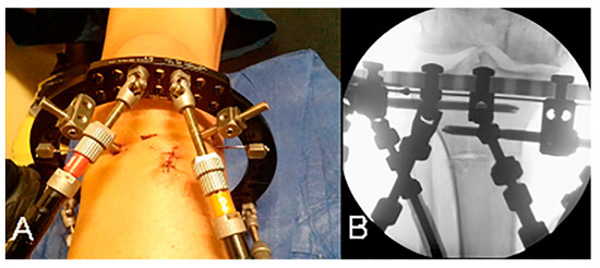
Figure 1.
(A) Open-wedge high tibial osteotomy performed with a small anterior incision. (B) Low-energy osteotomy just distal to the tibial tubercle.

Table 1.
Patient demographics.
The proximal reference ring was always applied first and placed parallel to the articular surface of the tibia in all patients, while the distal ring was orthogonal to the diaphysis. Frame configuration in all patients consisted of a proximal open ring, 180 mm in diameter, and a distal full ring, 155 mm in diameter. A combination of one or two K-wires and two half-pins was used for the fixation of the proximal ring to the bone, while the distal ring was fixed to the bone with two or three half-pins, according to the surgeon’s preference.
The osteotomy was performed after the complete fixation of the frame to the bone and the application of all six struts. Due to limited space provided between struts for surgical manipulations, the two anterior struts were removed before starting the osteotomy. After the completion of the osteotomy, these two struts were reapplied at their initial length. HTO was performed through a small anterior incision with low-energy drilling and the use of an osteotome for cracking the tibial cortex (Figure 1). Effort to preserve periosteum was made in all cases. The site of the osteotomy was as proximal as possible, just distal to the tibial tuberosity, due to limited space provided by the proximal ring placement. A biplane osteotomy was performed in nine patients for patellofemoral compartment decompression.
The TSF’s web application was used in all patients in order to analyze the deformity and calculate the required correction in all planes of the deformity. The configuration setup, including mounting and strut parameters, the number of wires and half-pins and their positioning, the relative angulation of the two rings at the beginning and the end of correction procedure, and the ring to bone offset calculation, was extracted from the device software and is described in more detail in Section 2.2.
A latency period to start the correction process was applied to all patients, and an immediate non-weight-bearing mobilization was allowed. Full weight-bearing started by the end of the correction program and according to callus formation progress.
The topography of the callus formation and the maturity patterns were analyzed in serial radiographs. Anteroposterior (AP) and lateral standing views of the knee joint were obtained every week during the correction period, and once a month until frame removal. The mechanical axis correction was assessed by measurement of the femorotibial angle (mechanical) (FTAm) in standing long leg alignment AP views. Pre- and post-operative measurements of the tibial slope were also made. The radiographic appearance of the callus was classified into 3 types:
- Circumferential: homogeneous callus as wide as the original bone;
- Eccentric: callus formation mainly at one corner of the osteotomy gap;
- Absent: only sparse calcification in the osteotomy gap.
2.2. Experimental Model
The purpose of this part of the study was to experimentally investigate the TSF setup used in the clinical investigation in order to correlate the clinical observations regarding callus formation presented in the previous section with the mechanical response of the TSF device. In the experimental investigation, axial compressive loading was considered the predominant loading mode during weight-bearing. For this purpose, an experimental model was set up, consisting of a TSF fixator with identical configuration to the clinical setup.
The typical TSF configuration as applied in the clinical treatment of HTO (Section 2.1) is shown in Figure 2. The TSF configuration consists of an upper (open) and lower ring with internal diameters of 180 mm and 155 mm, respectively. The TSF rings are connected to each other with six triangulating struts. Universal joints are used at the ring–strut connection points in order to allow for the rotational movement of the struts.
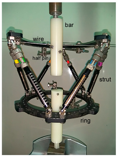
Figure 2.
Experimental setup of TSF fixator corresponding to the clinical case examined.
To simulate the upper and lower bone structure, two 30 mm diameter polyethylene bars were used, with lengths of 130 mm (upper part) and 139 mm (lower part). The upper bar was fixed on the open ring with two half-pins of 6 mm diameter and a pre-tensioned Kirschner wire of 1.8 mm diameter. The pre-tension applied on the wire during setup was 1000 N using the standard wire tensioner, included in the TSF instrumentation, and was confirmed by using an axial extensometer on the wire during pre-tensioning. As far as the element configuration is concerned with regard to the actual clinical case, clamping of the half-pins on the upper ring was such that the angle between them was 67° with respect to the center of the ring. The Kirschner wire had an internal angle of 45° and 112° with the first and second half-pin, respectively. The lower ring was fixed on the polyethylene bar using three half-pins of 5 mm diameter placed at an internal angle of 25–40°. The Kirschner wire was attached to the upper ring with screws, while the half-pins were attached to the rings with special rancho cube connectors, as shown in Figure 2. Fixation of the half-pins with the polyethylene bars was made using internal screwing. The axes of the upper and lower polyethylene bars were aligned at the center of each ring, and were perpendicular to the plane of the rings in the direction of uniaxial loading. During compressive displacement, simple support conditions in the upper bar were implemented to allow free rotation of the bar by using a metallic cylindrical element for surface contact (Figure 2). During gripping, the axis of the cylindrical element was aligned to the loading axis by default. Next, alignment of the cylindrical element axis with the axis of the upper bar was achieved by ensuring firstly the surface flatness of the polyethylene bar and then by using a measuring caliper for adjusting the position of the surface at the contact location.
The lower bar axis was aligned by default to the loading axis of the machine by including on the one edge of the bar a manufacturing detail in order to allow gripping of the bar directly on the machine wedges. Prior to the application of axial displacement resulting in compressive loading of the fixator frame, the space between bars was set at 35 mm.
The TSF fixator was placed on an MTS 810 universal testing machine, and a constant displacement rate of 5 mm/min was applied for uniaxial compression. During testing, the total displacement of the end supports as well as the magnitude of the applied compressive force were measured.
3. Results
3.1. Clinical Results
The median age at the time of surgery was 51 years (range: 38–58 years), while median follow-up was 60 months, ranging from 24 months to 120 months. The median latency to start correction was 6 days (range 5–10 days), and the median duration of correction was 16 days (range 10–20 days). An additional correction program was required in 1.8% of all cases. The median required total angle of correction according to the TSF’s program prescription given to the patients was 12° (range 5–18°). In nine patients (16% of all patients), a 2–5 mm of anterior translation of the tibial tubercle was made in order to decompress the patellofemoral joint. Radiographically, a median FTAm correction of 5° (range: 3–8°) was achieved and there was no virtual change in tibia slope. The median time of frame removal was 87 days (range 82–120 days). In Figure 3, a typical radiograph at the end of the correction period is shown. The clinical results are summarized in Table 2.
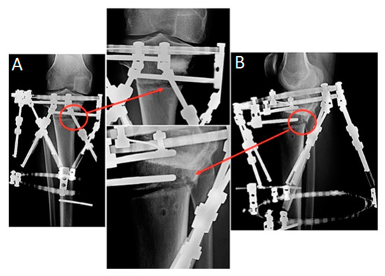
Figure 3.
Radiographs of a representative case at the end of the correction period. Callus formation eccentric pattern is marked with red circles: (A) anteroposterior and (B) lateral views.

Table 2.
Clinical results.
The measurements included in the study were presented using the median and range values, since the Shapiro–Wilk test of normality showed a significant deviation from normality for all the variables of interest. The statistical level of significance was set at 0.05 in all cases and the calculations were carried out with the use of SPSS v23.0 software.
With regard to the classification defined in Section 2.1, callus formation at the site of osteotomy was eccentric in all cases examined, regardless of patients’ gender and whether the patellofemoral compartment arthritis was present pre-operatively or not. As depicted in Figure 4, the consolidation process started from the posterolateral corner of the osteotomy gap and advanced anteromedially. A small uncovered area at the anteromedial part of the osteotomy site was evident at the time of frame removal in 40 cases (73% of all patients), while in the remaining 15 cases (27% of all patients) eccentric callus was formatted in the entire osteotomy gap.
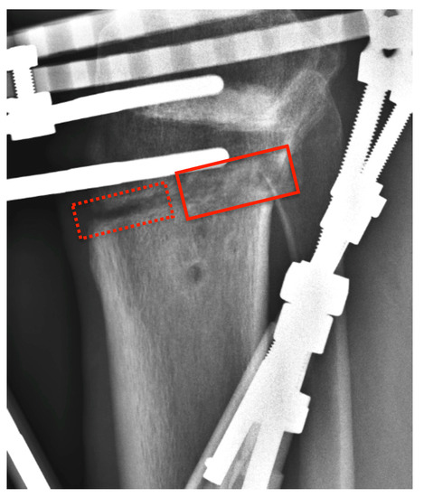
Figure 4.
Radiograph of the case presented in Figure 3 (lateral view) at the time of frame removal showing eccentric callus formation (solid rectangle). An uncovered area at the anteromedial part of the osteotomy site is evident (dashed rectangle).
Ten patients (18% of all patients) had a documented pin track infection, which necessitated the use of oral antibiotic therapy in six patients. There was no case of chronic bone infection. Two patients (3.6% of all patients) sustained deep vein thrombosis, with one case leading to pulmonary embolism that was treated uneventfully.
At the last follow up there was one patient who lost the initial correction after the apparently premature removal of the frame. None of the remaining patients required another operation or a total knee arthroplasty.
3.2. Experimental Results
3.2.1. Deformation under Uniaxial Compression
During compressive loading, the deformation constraints provided by the Kirschner wire and the half-pins in the upper ring resulted in a tilting (out-of-axis displacement) of the upper bar (Figure 5). The observed rotation was a result of the bending moment developed at the connection to the half-pins, and increased with increasing load. In the deformed state, the rotation of the axis of the upper bar relative to the axis of the lower bar resulted in an angle θ between them on the order of 8–10° (Figure 5B). In actual TSF in HTO, this rotation of the upper part of the bone causes premature localized contact of its lower end with the top surface of the lower part of the bone, contributing to the eccentric callus development observed clinically.
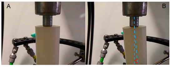
Figure 5.
(A) Undeformed and (B) deformed state of polyethylene bar axis at upper support, showing the development of angle θ during uniaxial compression.
The uniaxial compression test was interrupted at a total vertical displacement of 3.5 mm, at which point a vertical load of around 100 N was achieved, which is a physiologically relevant load at the early stages of patient partial weight-bearing post-operatively.
In Figure 6, the experimental (Figure 6A) and the corresponding clinical setup (Figure 6B) are compared. As shown in Figure 6, the positions of relative rotation of the upper part in the experimental model (Figure 6A) and in the clinical correction of TSF (Figure 6B) are consistent. The experimentally observed rotation, which under axial compression eventually led to localized contact between the cross sections of the upper and lower bar, provides a better understanding of the fixator’s mechanical response regarding its contribution to the asymmetric callus formation, as observed in the clinical cases.
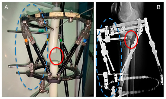
Figure 6.
Locations of asymmetric gap closure (solid circles) of (A) polyethylene bars and (B) bone surfaces, resulting from the same rotation direction about the half-pin support points (dashed circles).
3.2.2. Stiffness of TSF Configuration
The configuration of the TSF resulting from the number and positioning of stiffeners, such as half-pins and wires, has an immediate influence on the mechanical characteristics, specifically the frame stiffness. Consequently, it is the stiffness of the device that regulates the amount of vertical displacement under axial compression and determines contact or non-contact conditions of upper and lower bone parts, leading to premature callus formation. It is therefore important (including for clinical practice) to evaluate the influence of specific elements on the stiffness of the TSF frame.
Pre-tensioned Kirschner wires had an immediate effect on uniaxial compression stiffness due to the axial resisting forces they exerted on the bar (bone in the actual TSF) when bent, whereas half-pins contributed to both the bending and uniaxial compression stiffness, since they resisted both the axial and bending deformation of the bar. The influence of specific TSF element configurations on stiffness was examined by performing separate compression tests after removal of either the Kirschner wire from the upper ring or a half-pin from the lower ring.
The force–displacement behavior of the TSF was linear up to a value of 3.5 mm vertical displacement, as shown in Figure 7. The response was elastic, as confirmed upon unloading. From Figure 7, the measured stiffness of the reference TSF configuration (TSF1), described in Section 2.2 and calculated as the slope of the force–displacement curve, was 32 N/mm. In the same figure, the stiffness of the reference TSF configuration (TSF1) is compared against the stiffness of the device when removing the wire (TSF3) or removing a half-pin (TSF2). Removal of either the wire or a half-pin reduced the original stiffness of 32 N/mm to 27.5 N/mm (14% reduction) and 25.5 N/mm (20% reduction), respectively. Removal of one half-pin or one wire with regard to TSF1 corresponded to an increase in relative displacement between the two bone parts of 0.6–0.7 mm, under a constant compressive load of 100 kN.
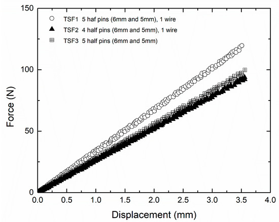
Figure 7.
Load displacement behavior of TSF with different configurations [32].
4. Discussion
The goal of the current investigation was to evaluate the clinical application and the mechanical characteristics of TSF in terms of callus formation and maturation pattern in an HTO environment. The comparison of TSF with other fixation methods (e.g., plates) used in HTO was beyond the scope of this study.
The appropriate time for frame removal is a complex decision process based on the surgeon’s experience upon the TSF external fixator as well as other external fixator systems used for performing HTO in patients with medial compartment arthritis [7,33,34]. General convention suggests that when three of four cortices demonstrate radiographic healing, the bone has enough intrinsic stability and the fixator can be removed [35]. Our study results have demonstrated that the median time of frame removal in HTO patients was 87 days (range: 82–120 days). This removal time is smaller than the times reported in other studies using TSF [23,36]. Robinson et al. [36] report a median time in the frame of 18 weeks (126 days), whereas Viskontas et al. [23] mention a longer time, reaching 23 weeks (161 days). The reported differences are probably due to the different frame configurations used and their impact in callus formation and maturity time.
Although proper bone regeneration and time for frame removal depend primarily on specific patient characteristics, several important parameters may be considered that assist callus development in fractured bone surfaces, and were investigated here using a suitable experimental method of the TSF. From the clinical point of view, the literature findings suggest that a suitable interfragmentary strain is required, which allows the micro-movement between fractured bone parts and assists the development of local pressure in the fractured bone surfaces, creating a callus formation pattern according to the applied pressure. The magnitude of applied local pressure, which stimulates bone growth, depends on the interfragmentary strain as well as the stiffness of the TSF. It has been reported that an interfragmentary strain of less than 10% between bone ends was necessary for desirable fracture union [37]. Ilizarov, in his experiments on canines, reported a direct correlation between frame stiffness and bone regeneration [13]. The local strains at the wedge-shaped space created at the osteotomy site are asymmetrically distributed and induce both mechanical and biological stimuli that lead to a specific pattern of callus formation [38]. The combination of half-pins with tensioned wires in circular external fixators has an additive effect on frame stiffness [25,39]. In the present study, we showed that the individual contribution of wire and pin elements on TSF fixator stiffness was similar. Hence, the use of pretensioned wires or half-pins to achieve a specific stiffness value still depends on clinical considerations for the adequate number and geometric characteristics of the transfixing components for each type of deformity. Additionally, removal of a wire or half-pin results in a respectable change in stiffness. This change was quantified, and may be used to assist clinical practice.
In terms of callus formation, there is no objective method that can be suggested to determine that a callus is biomechanically solid enough to withstand physiological loads. In our study, the callus formation pattern developed in all HTO patients was eccentric. The clinical findings revealed that the consolidation process was advancing from the point of maximum bone to bone contact, at the posterolateral corner of the osteotomy, leaving a small anteromedial gap by the time of frame removal in most cases. The results obtained from the experimental model indicate that vertical deflection of the upper bar during weight-bearing in the TSF fixator is accompanied by a rotation of the bar axis. This rotation results in an angle between the bar axes in the undeformed and deformed state and a corresponding angle between the displaced and the initially parallel cross section surfaces. The formation of the angle is in the same direction as the angle applied initially during the open-wedge-correction osteotomy of the tibia. The fact that both angles are in the same direction enhances rather than weakens the contact of bone surfaces at the posterolateral corner of the osteotomy site, which in turn causes a loading pattern that tends to close the fracture gap eccentrically, and thus creates a convenient biomechanical environment for unsymmetrical callus formation. An angle development in the opposite direction would partly annihilate the initial angle and inhibit bone contact. Beyond the mechanical response of the TSF external fixator that was examined in the present study, other parameters such as gait patterns under partial weight-bearing, muscle strains and the soft tissue envelope asymmetrically surrounding the tibia might also contribute to spatial callus formation and its eccentric appearance [40].
5. Conclusions
The deformity correction process in HTO and the mechanical response of the TSF under compressive loads may be regarded as combined contributions, leading to asymmetric gap closure and promoting the clinically observed eccentric callus formation at the osteotomy site. This study provides a useful consideration in clinical decision-making regarding the callus formation process when TSF external fixators are applied in open-wedge HTOs.
Author Contributions
N.K. contributed to the conceptualization, methodology, data curation of clinical results, writing, review, and editing of the article. A.T.K. was involved in the conceptualization and methodology, design of the experimental model and conducting the mechanical tests, data curation, writing, and editing. L.A.S. contributed to the conceptualization and methodology, analysis and design of the experimental model, as well as the writing, and editing of the article. K.B. and S.V. were involved in the conceptualization, methodology, writing, and editing. N.A. and K.N.M. contributed to the conceptualization, methodology development, and editing of the article. All authors have read and agreed to the published version of the manuscript.
Funding
This research received no external funding.
Institutional Review Board Statement
The study was conducted according to the guidelines of the Declaration of Helsinki, and approved by the Ethics Committee of the University Hospital of Larissa, Thessaly, Greece, with protocol approval number 25178/22-11-2011.
Informed Consent Statement
Informed consent was obtained from all patients involved in the study.
Data Availability Statement
The data presented in this study are available on request from the corresponding author.
Acknowledgments
The authors would like to thank Anastasios Mavraganis for help with the mechanical tests.
Conflicts of Interest
The authors declare no conflict of interest.
References
- Agneskirchner, J.D.; Freiling, D.; Hurschler, C.; Lobenhoffer, P. Primary stability of four different implants for opening wedge high tibial osteotomy. Knee Surg. Sport. Traumatol. Arthrosc. 2005, 14, 291–300. [Google Scholar] [CrossRef] [PubMed]
- Jung, W.-H.; Chun, C.-W.; Lee, J.-H.; Ha, J.-H.; Kim, J.-H.; Jeong, J.-H. Comparative Study of Medial Opening-Wedge High Tibial Osteotomy Using 2 Different Implants. Arthrosc. J. Arthrosc. Relat. Surg. 2013, 29, 1063–1071. [Google Scholar] [CrossRef]
- Izaham, R.M.A.R.; Kadir, M.R.A.; Rashid, A.H.A.; Hossain, G.; Kamarul, T. Finite element analysis of Puddu and Tomofix plate fixation for open wedge high tibial osteotomy. Injury 2012, 43, 898–902. [Google Scholar] [CrossRef] [PubMed]
- Rollo, G.; Pichierri, P.; Grubor, P.; Marsilio, A.; Bisaccia, M.; Grubor, M.; Pace, V.; Lanzetti, R.M.; Giaracuni, M.; Filipponi, M.; et al. The challenge of nonunion and malunion in distal femur surgical revision. Med. Glas. 2019, 16, 1–10. [Google Scholar] [CrossRef]
- Adili, A.; Bhandari, M.; Giffin, R.; Whately, C.; Kwok, D.C. Valgus high tibial osteotomy. Knee Surg. Sport. Traumatol. Arthrosc. 2001, 10, 169–176. [Google Scholar] [CrossRef] [PubMed]
- Bisaccia, M.; Rinonapoli, G.; Meccariello, L.; Caraffa, A.; Cukierman, B.; Iborra, J.R. The Challenges of Monoaxial Bone Transport in Orthopedics and Traumatology. Ortop. Traumatol. Rehabil. 2017, 19, 373–378. [Google Scholar] [CrossRef] [PubMed]
- A Catagni, M.; Guerreschi, F.; Ahmad, T.S.; Cattaneo, R. Treatment of genu varum in medial compartment osteoarthritis of the knee using the Ilizarov method. Orthop. Clin. N. Am. 1994, 25, 509–514. [Google Scholar] [CrossRef]
- Fowler, J.; Gie, G.; MacEachern, A. Upper tibial valgus osteotomy using a dynamic external fixator. J. Bone Jt. Surg. 1991, 73, 690–691. [Google Scholar] [CrossRef]
- Kitson, J.; Weale, A.; Lee, A.; MacEachern, A. Patellar tendon length following opening wedge high tibial osteotomy using an external fixator with particular reference to later total knee replacement. Injury 2001, 32, 140–143. [Google Scholar] [CrossRef]
- Nakamura, E.; Mizuta, H.; Kudo, S.; Takagi, K.; Sakamoto, K. Open-wedge osteotomy of the proximal tibia with hemicallotasis. J. Bone Jt. Surg. 2001, 83, 1111–1115. [Google Scholar] [CrossRef]
- Weale, A.E.; Lee, A.S.; MacEachern, A.G. High Tibial Osteotomy Using a Dynamic Axial External Fixator. Clin. Orthop. Relat. Res. 2001, 382, 154–167. [Google Scholar] [CrossRef]
- Claes, L.; Eckert-Hübner, K.; Augat, P. The effect of mechanical stability on local vascularization and tissue differentiation in callus healing. J. Orthop. Res. 2002, 20, 1099–1105. [Google Scholar] [CrossRef]
- A Ilizarov, G. The tension-stress effect on the genesis and growth of tissues. Part I. The influence of stability of fixation and soft-tissue preservation. Clin. Orthop. Relat. Res. 1989, 238, 249–281. [Google Scholar] [CrossRef]
- Yamaji, T.; Ando, K.; Wolf, S.; Augat, P.; Claes, L. The effect of micromovement on callus formation. J. Orthop. Sci. 2001, 6, 571–575. [Google Scholar] [CrossRef] [PubMed]
- Binski, J.C. Taylor Spatial Frame in Acute Fracture Care. Tech. Orthop. 2002, 17, 173–184. [Google Scholar] [CrossRef]
- Al-Sayyad, M.J. Taylor Spatial Frame in the Treatment of Pediatric and Adolescent Tibial Shaft Fractures. J. Pediatr. Orthop. 2006, 26, 164–170. [Google Scholar] [CrossRef] [PubMed]
- Blondel, B.; Launay, F.; Glard, Y.; Jacopin, S.; Jouve, J.-L.; Bollini, G. Limb lengthening and deformity correction in children using hexapodal external fixation: Preliminary results for 36 cases. Orthop. Traumatol. Surg. Res. 2009, 95, 425–430. [Google Scholar] [CrossRef]
- Eidelman, M.; Bialik, V.; Katzman, A. Correction of deformities in children using the Taylor spatial frame. J. Pediatr. Orthop. B 2006, 15, 387–395. [Google Scholar] [CrossRef]
- Naqui, S.Z.H.; Thiryayi, W.; Foster, A.; Tselentakis, G.; Evans, M.; Day, J.B. Correction of Simple and Complex Pediatric Deformities Using the Taylor-Spatial Frame. J. Pediatr. Orthop. 2008, 28, 640–647. [Google Scholar] [CrossRef]
- Rozbruch, R.S.; Segal, K.; Ilizarov, S.; Fragomen, A.T.; Ilizarov, G. Does the Taylor Spatial Frame Accurately Correct Tibial Deformities? Clin. Orthop. Relat. Res. 2010, 468, 1352–1361. [Google Scholar] [CrossRef] [PubMed]
- Feldman, D.S.; Madan, S.S.; Koval, K.J.; van Bosse, H.J.P.; Bazzi, J.; Lehman, W.B. Correction of Tibia Vara With Six-Axis Deformity Analysis and the Taylor Spatial Frame. J. Pediatr. Orthop. 2003, 23, 387–391. [Google Scholar] [CrossRef] [PubMed]
- Feldman, D.S.; Shin, S.S.; Madan, S.; Koval, K.J. Correction of Tibial Malunion and Nonunion With Six-Axis Analysis Deformity Correction Using the Taylor Spatial Frame. J. Orthop. Trauma 2003, 17, 549–554. [Google Scholar] [CrossRef] [PubMed]
- Viskontas, D.G.; MacLeod, M.D.; Sanders, D.W. High tibial osteotomy with use of the Taylor Spatial Frame external fixator for osteoarthritis of the knee. Can. J. Surg. 2006, 49, 245. [Google Scholar]
- Zhang, W.; Wan, C.; Zhang, T.; Wang, M.; Liu, Z.; Zhao, Y. Clinical application of Taylor spatial frame in adjustment of lower extremity force line of knee medial compartmental osteoarthritis. Chin. J. Reparative Reconstr. Surg. 2020, 34, 452–456. [Google Scholar] [CrossRef]
- Henderson, E.R.; Feldman, D.S.; Lusk, C.; van Bosse, H.J.; Sala, D.; Kummer, F.J. Conformational Instability of the Taylor Spatial Frame. J. Pediatr. Orthop. 2008, 28, 471–477. [Google Scholar] [CrossRef]
- Antoci, V.; Voor, M.J.; Antoci, V., Jr.; Roberts, C.S. Biomechanics of Olive Wire Positioning and Tensioning Characteristics. J. Pediatr. Orthop. 2005, 25, 798–803. [Google Scholar] [CrossRef] [PubMed]
- Henderson, D.J.; Rushbrook, J.L.; Stewart, T.D.; Harwood, P.J. What Are the Biomechanical Effects of Half-pin and Fine-wire Configurations on Fracture Site Movement in Circular Frames? Clin. Orthop. Relat. Res. 2015, 474, 1041–1049. [Google Scholar] [CrossRef] [PubMed][Green Version]
- Khurana, A.; Byrne, C.; Evans, S.; Tanaka, H.; Haraharan, K. Comparison of transverse wires and half pins in Taylor Spatial Frame: A biomechanical study. J. Orthop. Surg. Res. 2010, 5, 23. [Google Scholar] [CrossRef]
- Lenarz, C.; Bledsoe, G.; Watson, T.J. Circular External Fixation Frames with Divergent Half Pins: A Pilot Biomechanical Study. Clin. Orthop. Relat. Res. 2008, 466, 2933–2939. [Google Scholar] [CrossRef][Green Version]
- Henderson, D.J.; Rushbrook, J.L.; Harwood, P.J.; Stewart, T.D. What Are the Biomechanical Properties of the Taylor Spatial Frame™? Clin. Orthop. Relat. Res. 2016, 475, 1472–1482. [Google Scholar] [CrossRef]
- Tan, B.; Shanmugam, R.; Gunalan, R.; Chua, Y.; Hossain, G.; Saw, A. A Biomechanical Comparison between Taylor’s Spatial Frame and Ilizarov External Fixator. Malays. Orthop. J. 2014, 8, 35–39. [Google Scholar] [CrossRef] [PubMed]
- Mavraganis, A. Ilizarov and Taylor Spatial Frame Orthopedic Frames for External Bone Regeneration: Experimental Inves-tigation and Computational Analysis of Their Mechanical Behavior. Diploma Thesis, Department of Mechanical Engineering, University of Thessaly, Volos, Greece, 2015. [Google Scholar]
- Gunes, T.; Sen, C.; Erdem, M. Tibial slope and high tibial osteotomy using the circular external fixator. Knee Surgery, Sports Traumatol. Arthrosc. 2006, 15, 192–198. [Google Scholar] [CrossRef] [PubMed]
- Sen, C.; Kocaoglu, M.; Eralp, L. The advantages of circular external fixation used in high tibial osteotomy (average 6 years follow-up). Knee Surg. Sports Traumatol. Arthrosc. 2003, 11, 139–144. [Google Scholar] [CrossRef]
- Fragomen, A.T.; Rozbruch, S.R. The Mechanics of External Fixation. HSS J. 2006, 3, 13–29. [Google Scholar] [CrossRef]
- Robinson, P.M.; Papanna, M.C.; Somanchi, B.V.; Khan, S.A. High tibial osteotomy in medial compartment osteoarthritis and varus deformity using the Taylor spatial frame: Early results. Strat. Trauma Limb Reconstr. 2011, 6, 137–145. [Google Scholar] [CrossRef]
- Egol, K.A.; Kubiak, E.N.; Fulkerson, E.; Kummer, F.J.; Koval, K.J. Biomechanics of Locked Plates and Screws. J. Orthop. Trauma 2004, 18, 488–493. [Google Scholar] [CrossRef]
- Augat, P.; Simon, U.; Liedert, A.; Claes, L. Mechanics and mechano-biology of fracture healing in normal and osteoporotic bone. Osteoporos. Int. 2004, 16, S36–S43. [Google Scholar] [CrossRef]
- Kristiansen, L.P.; Steen, H.; Reikerås, O. No difference in tibial lengthening index by use of Taylor Spatial Frame or Ilizarov external fixator. Acta Orthop. 2006, 77, 772–777. [Google Scholar] [CrossRef]
- Klein, P.; Schell, H.; Streitparth, F.; Heller, M.; Kassi, J.-P.; Kandziora, F.; Bragulla, H.; Haas, N.P.; Duda, G.N. The initial phase of fracture healing is specifically sensitive to mechanical conditions. J. Orthop. Res. 2003, 21, 662–669. [Google Scholar] [CrossRef]
Disclaimer/Publisher’s Note: The statements, opinions and data contained in all publications are solely those of the individual author(s) and contributor(s) and not of MDPI and/or the editor(s). MDPI and/or the editor(s) disclaim responsibility for any injury to people or property resulting from any ideas, methods, instructions or products referred to in the content. |
© 2023 by the authors. Licensee MDPI, Basel, Switzerland. This article is an open access article distributed under the terms and conditions of the Creative Commons Attribution (CC BY) license (https://creativecommons.org/licenses/by/4.0/).
