1. Introduction
Mixed Reality (MR) is defined as the combination of reality, augmented reality, augmented virtual, and virtual reality combining real objects and virtual objects. MR has a wide range of applications, from museum exhibition [
1] to civil aircraft design [
2]. However, one of the most frequently studied applications of MR is guiding assembly tasks [
3]. Additionally, it is also used in a variety of other fields such as aerospace [
4], automotive [
5], medicine [
6], and education [
7].
In industry, MR technology has also been used for robot control, as in Christyan Cruz’s integration [
8] of a 6DoF robotic arm into Unitree’s quadruped robot ARTU-R, a work whose main contribution focused on high-level control of robot groups by MR. Elsewhere, Dimitris [
9] focused on building a digital twin of the robotic arm to achieve real-time remote and safe operation. Based on this digital twin technology, Meysam [
10] simulates CNC machining in Microsoft HoloLens to observe the machining process before the actual process begins. Incorporating MR technology into the design phase allows more relevant people to participate. Guo [
2] has built a cockpit control device design and evaluation system based on mixed reality technology, which ensures a more efficient and realistic design environment for aircraft designers. It also provides a user evaluation environment that enables pilots to be involved in the design of the cockpit at an early stage. In the field of construction machinery research, MR technology is generally used for information prompting in the simulation of construction machinery—to help the driver to obtain information more intuitively [
11], to reduce their mental burden [
12], or as a virtual training system [
13]. However, there is little research into design in either the research or manufacturing stage of construction machinery.
Therefore, this paper proposes a holographic visualization verification platform for construction machinery digital prototypes based on virtual terminal equipment, and mainly supported by mixed reality technology. The platform would be utilized for research in the design and development stage, the manufacturing stage, the sales circulation stage, and the client verification stage of construction machinery. The latter phase is committed to carrying out more efficient design, using research and development verification—including intelligent manufacturing, promotion, and publicity process of user experience—to improve use stage verification through applying MR technology support in the whole life cycle of construction machinery.
As shown in
Figure 1, the visual verification platform consisted of six modules: virtual assembly design verification, virtual-real integration design and assembly verification of semi-physical space, and man-machine verification; remote multi-user collaborative review; digital twin visualization of the production line; factory production line layout; complete machine modeling verification; virtual simulation and motion simulation control of construction machinery equipment.
3. Materials and Methods
This study proposes a holographic visualization verification platform for construction machinery digital prototypes based on virtual terminal devices. Users can conduct a series of verification and practice functions on the platform. For example, assembly verification and human-machine verification: verify the design and installation, human-machine vision, and accessibility of parts and interiors of construction machinery in a mixed reality environment. Realize remote collaboration in different places through servers. Relevant design engineers, leaders in charge can share the same virtual scene through MR headwear equipment, VR headwear equipment, and mobile equipment. The communication between multiple terminal users is realized through voice, all users can operate on parts and interiors, so that problems can be adjusted in time. The access of mobile devices can also be termed a third-party view because in mobile, both real and virtual objects as well as the operation of virtual objects can be observed at the same time. Meanwhile, offsite collaboration can also be used for the remote monitoring of production lines, which is based on the digital twin visualization of production lines. Users can also verify the factory production line layout while accessing the platform by placing the virtual production line into the actual factory environment in order to evaluate the rationality of the production line layout. Users can easily replace the appearance of construction machinery with the help of MR technology, including features such as color, material, shape, etc., which can be displayed to the public and to customers to experience. Finally, users can virtually operate engineering equipment in the scene and simulate the construction process in a hybrid virtual environment with real immersion and interactivity.
The second-generation HoloLens mixed reality device was used in the study. In the mixed reality device, holographic content is superimposed on top of real objects, with holograms allowing for gaze, gesture, and voice interaction. Users can interface with both real-world objects and holographic content in real-time. Mixed reality devices allow for multiple users to share the same holographic environment, and to interact simultaneously. This is the basic technical support for remote collaboration.
Before building a project, the model and UI must be prepared by special computer software, selecting Unity 2022 for the game engine, in which the virtual environment was built and finally published to HoloLens2.
To realize this huge visual verification platform, this paper studies the key technologies of MR application in the field of construction machinery. The following section mainly introduces 8 techniques utilized throughout the whole research. Included among these are: the SUSAN corner point inspection technique, which is used to identify the edges of objects in the real world; the data exchange method based on implicit feature expression, which is used to solve the problem of information transmission between MR multi-terminal devices. Below, we also introduce: voice communication technology and third-party perspective solutions for MR remote collaboration; dynamic loading and interference collision detection technology for 3D models in the process of virtual assembly; behavior rule simulation technology based on finite state machine for the remote monitoring of production line manipulators; and behavior rule simulation technology based on joint collaborative motion simulation technology used in complex construction machinery.
3.1. SUSAN Corner Point Inspection
The simple, fast, efficient, and noise-resistant SUSAN operator was first proposed by Smith and Brady in 1997 [
37]. The operator uses a circular template with diameter D as shown in
Figure 2a to move around the image. The center of the template is called the “nucleus”. The difference between the gray value of the pixel point inside the template and the gray value of the center of the template is determined by whether the gray difference is less than the threshold t. If the pixel point is determined to be in the same region as the center of the template, the region is called the nucleus similarity region (Univalue Segment Assimilating Nucleus). The SUSAN operator determines whether the pixel at the nucleus position is a corner point by determining the area of the nucleus similarity region. Here,
Figure 2b shows the USAN area schematic.
The formula used to determine whether a pixel point belongs to the USAN zone is:
In Equation (1),
I(
x,
y) is the gray value of the pixel points other than the kernel, and
I(
x0,
y0) is the gray value of the pixel points corresponding to the kernel. The more accurate Equation (2) is generally used in the actual calculation instead.
The USAN area at pixel point (
x0,
y0) in the image is calculated by Equation (3):
where
n is the number of non-nuclear pixels in the circular template. If the USAN value of a pixel point is less than a specific threshold, that point is considered as the initial corner point. The initial response function value for the initial focus is calculated using Equation (4):
g is the geometric threshold for noise suppression. If R(xi, yi) is the maximum value in the domain, then (xi, yi) is the corner point.
3.2. Data Exchange Based on Implicit Feature Expression
Real-time and efficient collaborative data exchange is the key to realizing the collaboration of multiple XR terminals. The data exchange method based on implicit feature expression has the characteristics of small and real-time transmission data. The implementation process is shown in
Figure 3. The specific steps are as follows:
Client 1 calls the API function to extract implicit expression information of all model-building features as transmission data;
Data encapsulation of implicit feature expression information and serialization;
Serialized data is distributed through the server;
Client 2 receives the data and deserializes the network encapsulation message and parses it to identify and extract the implicit expression parameters of the features;
After conversion, the API function is called for feature reconstruction and displayed in Client 2.
In response to the characteristics of multi-terminal, MR equipment replication-based collaboration, object references are divided into direct references and indirect references. Directly referenced objects refer to the operational objects when editing parts or features in collaboration. They are referenced by object identification numbers, a system which is simple to execute, and spatial mapping is used to realize the direct referencing of models. The indirect reference object refers to the topological object of the auxiliary reference and operational object. The set matching algorithm is used to realize the indirect object reference between models.
Geometric matching algorithm framework: when determining a referenced object according to the network message, the pickup type of the shape unit, the geometric feature value of the referenced object, and the set feature point are given first; then, an AABB hierarchical envelope box, i.e., a feature envelope box, is constructed with the feature point as the center, and the edge length can be set according to the drawing accuracy of the current scene, usually taking 5 units. Finally, the feature envelope box is used to intersect with the object-oriented dynamic. The local identification number of the referenced object is determined by the collision intersection of the nodes of the octree. Since the algorithm does not depend on the naming of topological entities, the operation order, and the initial state of the design, it is also applicable to “late joining” clients.
3.3. Voice Communication
The basic function of collaboration is the two-way transmission of voice, with each application using voice as the basis for communication. For the large-scale organization of complex integrated test environments, it is first necessary to command the test personnel of the whole environment at the control end as a means of improving the global control capability. In the case of multi-task, multi-team work in the parallel and irregular working area, a multi-node voice communication system is needed to ensure that any member of any team can join the communication group of this team at any location. Additionally, a multi-node system that is designed based on data distribution service ensures that communication between groups does not interfere with each other. A Mirror Networking framework is used for voice transmission, and the call quality can be improved by echo cancellation and noise suppression technology. The communication module that supports multiplayer real-time voice on multi-terminal devices (such as MR headset Microsoft HoloLens2 and VR headset HTC VIVE) is deployed, which can realize multi-platform real-time voice communication.
The Mirror Networking framework consists of a series of layers that add functionality. This networking framework has message handlers, generic high-performance serialization, distributed object management, state synchronization, and network classes: server, client, connection, etc. The network architecture diagram is shown in
Figure 4.
The relationship between the server, local client, and client is shown in
Figure 5. Note that the client also acts as the host, which means that the client himself is the “local client”. The local client is also connected to the host server, with both running on the same computer. The other two remote clients, each located at different terminals, can connect to the host server at the same time in order to achieve multi-platform voice communication to the terminals.
3.4. Third-Party Perspective
Microsoft provided Spectator View, a third-party viewpoint solution, which involves the user in the operation of virtual objects. Firstly, the product filters the third-party perspective through another HoloLens to obtain spatial positioning, then through a camera to obtain the user’s specific actions, using the video-capture card in a workstation for fusion. Finally, the user’s actions are rendered to the screen. Spectator View is the earliest third-party viewpoint solution, but it has many problems, such as instability, no interaction, and high cost. In this paper, a lightweight third-party viewpoint solution was designed to replace Spectator View.
This solution first obtains the spatial coordinate position of the third-party view device through the camera module of HoloLens, then unifies the spatial coordinate system of the HoloLens device and the third-party view device supporting ARCore through the spatial coordinate system conversion algorithm. Finally, it displays the virtual content in HoloLens and supports touch-based interactive operation in the third-party view device. The flow of the third-party view is shown in
Figure 6.
3.4.1. QRCode-Based Third-Party View Device Identification Method
There are two methods for third-party perspective device identification, namely computer vision-based and QRCode-based. The computer vision-based approach requires modeling all known ARCore-enabled devices and identifying the specific model and location of the device through a neural network. This method entails a large amount of manually labeled data for training and has poor recognition stability and complex implementation, as well as poor ease of use. It also involves retraining a new model for recognition if a new device appears. The QRCode-based method does not require a large amount of data to train the model and has high recognition efficiency and stability. By contrast, this approach makes it very simple to be ported to new devices in the future. The QRCode-based approach is therefore more suitable for the recognition of third-party viewpoint devices, and is implemented using the special toolkit. Each QRCode corresponds to a 3D coordinate system, and the special toolkit identifies the position of the QRCode in space and returns this 3D coordinate system. The position information and the coordinate system information are used to calculate the coordinates of the third-party perspective device in real-world space, as well as the device’s rotation angle and its corresponding quaternion. At this point, the identification of the third-party view device is completed. The coordinate information, rotation angle information, and the corresponding quaternion information will be used in the subsequent spatial coordinate alignment algorithm. The QRCode identification steps are as follows.
The recognition module is invoked by clicking the recognition button in HoloLens and sending a request to the server to start recognition.
The third-party viewpoint device displays the QRCode on the screen after receiving the start recognition request distributed by the server.
HoloLens recognizes the QRCode on the screen of the third-party view device.
To complete the recognition of the device, calculate the coordinates of the third-party view device in the real-world space as well as the device’s rotation angle and its corresponding quaternion.
3.4.2. Spatial Coordinate Alignment Algorithm Based on ARCore Continuous Space Localization
Both HoloLens and ARCore-enabled devices have the function of continuous spatial localization, which can model real space and display fixed virtual content within it. Due to the difference in devices, the coordinate systems of the two will be different when recognizing the same real space. The problem needing to be solved by the spatial coordinate alignment algorithm that is based on ARCore’s continuous spatial localization is how to align the spatial coordinates of the two devices so that they can accurately synchronize their respective operations, and finally complete the third-party perspective display function. This algorithm uses HoloLens to identify the ARCore-enabled devices and obtain the six-dimensional coordinate vectors
r (relative spatial position (
x,
y,
z) and relative rotation angle (
α,
β,
γ)) of the ARCore-enabled devices relative to the virtual content in the HoloLens coordinate system. The virtual content is transformed from under the HoloLens coordinate system to under the ARCore device coordinate system through the spatial mapping rule
T. Finally, the spatial coordinate system’s alignment is completed, as in Equation (5). Through this algorithm, the virtual content in the third-party view device can be fixed in the real world without the problem of jittering with the movement of the camera.
There are two problems in spatial mapping: the first is that HoloLens and ARCore use different coordinate system axis orientations, so it is necessary to use rotation transformation to solve the axis orientation problem; the second is that when considering the portability problem, the distance between the camera and the center of the device is different for different ARCore devices, so it is necessary to transform the spatial position of the virtual content. In summary, the mapping rule
T can be divided into two parts: rotation angle mapping
TR and spatial position mapping
TS, as in Equation (6).
Considering the portability issue, the distance between the camera and the center of the device is different for different ARCore devices. The distance between the camera and the center of the device can be expressed as a 3-dimensional vector
Coffset (spatial offset (
x,
y,
z)), while the spatial location mapping
TS can be expressed as Equation (7).
3.5. Dynamic Model Loading
In addition to loading the model itself, 3D model-loading also requires loading scripts, maps, and textures attached to the model, which cannot be satisfied by common databases such as MySQL and Oracle. As shown in
Figure 7, by establishing the MR cloud data repository to collect, store, process, and apply 3D mixed reality data, and applying the cloud server data push, the mixed reality content is dynamically loaded to the MR client interactively to realize the interconnection between the design side, server-side, and verification side. In contrast, Asset Bundle performs well in data management and compression size; the 3D model in Asset Bundle is loaded into the real scene in the MR mixed reality virtual environment by concurrent and asynchronous loading, which ensures no lag in the loading process and improves user experience.
3.6. Virtual Assembly Interference Collision Detection
Based on the axis-aligned enclosing box technology, semi-physical platforms and 3D parts have corresponding enclosing boxes. The model is enclosed by a rectangular box, and the coordinates (
x,
y,
z) of any point of the model in space satisfy Equation (8):
Figure 8 is a diagram of the bounding box of the 3D component model. When an object moves in space, its enclosing box also moves with it. When two enclosing boxes are in contact in space, it is considered that two objects have interfered with the collision. At this time, a color change is applied to the surface of the interfering object. For instance, the color of the interference collision border changes to red, which will have a psychological impact on the user and make him aware of the interference, in the event the assembly process encounters problems and needs to be adjusted in good time.
3.7. Behavior Rule Simulation Based on Finite State Machine
To make the state-switching of the digital twin in the virtual environment consistent with the discrete state-behavior of the real physical object, a finite state machine (FSM)-based algorithm is used to establish a finite set of states for the robot arm behavior under the finite set of input commands from the physical side. This means that the real-time state-switching of the twin can be completed based on message listening.
A finite state machine exists in one of a finite set of states at any given moment. When it gets an input character, it will transition from its current state to another state or remain in its current state. Any FSM can be described by a state transition graph, such as that seen in
Figure 9. Here, the nodes on the graph represent a state in the FSM and the directed weighted edges represent the change of state when the input character is given. If there is no directed edge corresponding to the current state and the input character, the FSM will enter the “Doom State”, and will remain in the “Doom State” thereafter. There are two special states in the state transition diagram: State 1 is called “start state”, which represents the initial state of the FSM. State 6 is called “end state”, which indicates that the input character sequence is successfully recognized.
When starting an FSM, the FSM must first be placed in the “start state”, and then a sequence of characters is entered. Eventually the FSM reaches the “end state” or “extinction state”.
3.8. Based on Joint Collaborative Motion Simulation Technology of Complex Construction Machinery
This paper develops a real-time interactive system and motion simulation system for construction machinery. The system architecture is shown in
Figure 10, including mixed reality hardware, a manipulation control handle, a simulation control module, spatial mapping, a collision detection module, and an information storage module. By establishing complex mechanical constraints in the operation simulation of engineering equipment and by introducing simple constraints in the physical engine to realistically represent the motion process of each part of engineering equipment, the problem of balancing real-time and simulation effect of motion simulation is resolved. The operator can virtually control the engineering equipment in the scene and simulate the construction process in the mixed virtual environment with a combination of real immersion and interactivity, thus providing a platform-independent virtual interactive simulation method that can meet interactivity and real-time.
As shown in
Figure 11, the implementation of the motion simulation method for this system includes the following steps:
Configure the mixed reality hardware, manipulation control handle, and server; that is, connect the mixed reality hardware to the server and the manipulation control handle to the server for communication;
Load the virtual model to the mixed reality hardware; that is, the server transfers the stored virtual scene data to the mixed reality hardware, and after the mixed reality hardware recognizes the actual environment information, the virtual scene is fused with the real scene to present the virtual-reality fusion scene;
The user makes operation input by manipulating the control handle; if the user operation input is wrong, the error message is prompted; if the user operation input is correct, the dynamics simulation calculation is carried out, and the simulation calculation result is output to the scene management and graphic image real-time rendering module; according to the simulation calculation result of the dynamics simulation calculation module, the scene management and graphic image real-time rendering module updates the motion state of the 3D model of engineering equipment in the virtual scene in real-time, and outputs the operation result to the mixed reality hardware to show to the operator;
Display the 3D model of engineering equipment in the virtual scene and update it in real-time; in step three in the real construction site environment, display it in a fusion of virtual reality and reality; at the same time, carry out collision detection and real-time motion interference simulation between virtual objects and real scene objects. If interference occurs between the detection and the real environment, send the interference information prompt to the operator wearing the mixed reality hardware, and if no interference occurs between the detection and the real environment, continue to perform the next verification and training tasks;
Write the operation process to the information storage module, carry out the process of the operation process information record storage, and complete the task.
4. Results
To test the method proposed in the visual verification platform, this paper designs six application cases in the whole life cycle of construction machinery equipment, corresponding to six modules of the platform, involving the construction machinery equipment: loader, tractor, mechanical arm, high-altitude working platform, and covering as many product types as possible.
4.1. Verification of Semi-Physical Reality Integration Design of Loader Cab
This section introduces a case of semi-physical virtual reality fusion design verification of a loader cab based on XR collaboration.
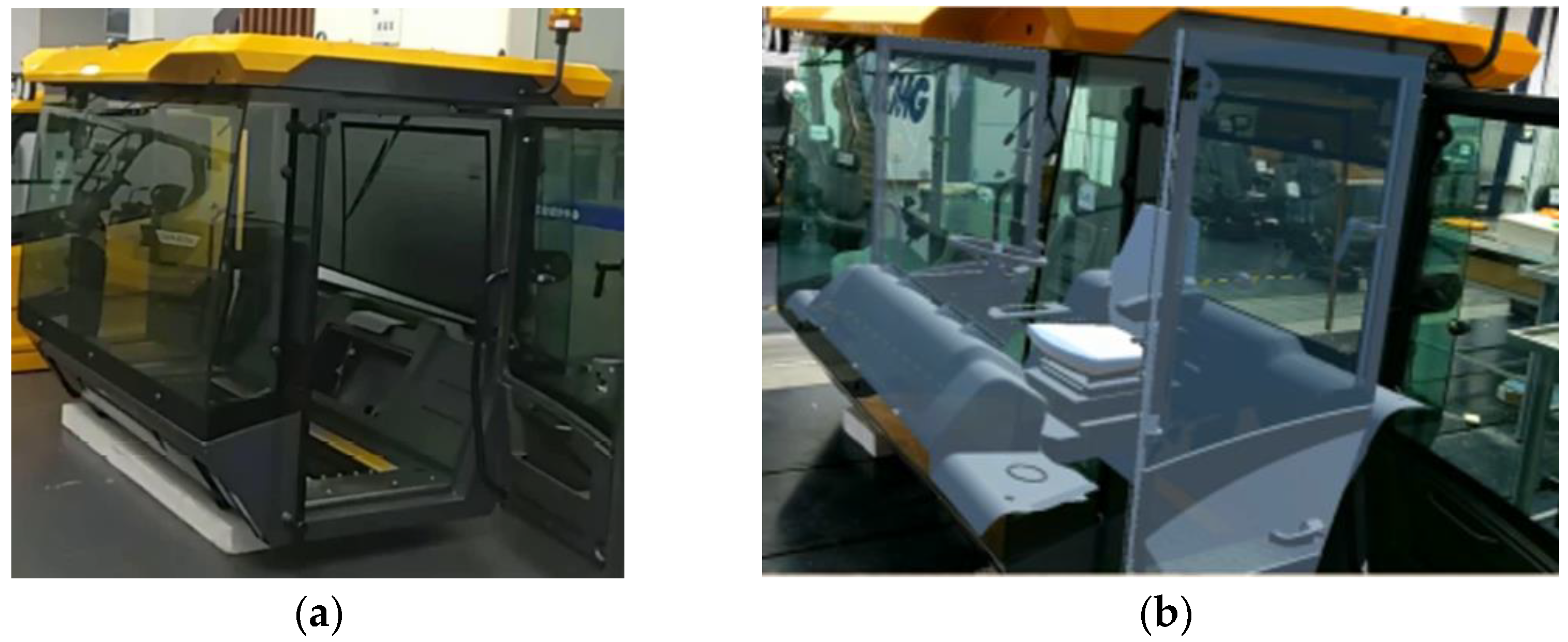
Figure 12 shows the semi-physical and virtual assembly effect of the cab. In the design verification process, the designer wears an MR headset, and in this case, the best effect Microsoft HoloLens2 is selected in the current market. According to the installation sequence of the assembly path planning, the virtual 3D parts model is sequentially assembled to the semi-physical cab, then the assembly verification is completed. To satisfy different design requirements, the parts can be obtained from the server in different dynamic styles.
Figure 13 shows an example of assembling a steering wheel. A logical constraint relationship is established between the cab as a semi-physical object and the assembly unit. The target position of the part to be assembled is then calculated in real-time. The installation position and angle are automatically matched when it lies within the threshold of the assembly range, which realizes the automatic adsorption function of the part to the corresponding installation position magnetically. When the virtual 3D model collides with semi-physical or other virtual models, it can detect and remind the assemblers of the color change of the outer frame. Thanks to the assembly path planning and collision detection technology, the whole virtual assembly verification process of the cab takes about 15 min, which shortens the verification time and facilitates repeated verification.
In addition, man-machine verification can also be accomplished on the physical human-machine test rig.
Figure 14a shows the physical view of the man-machine test rig. The man-machine verification process is shown in
Figure 14b, where the cabs are virtually fused on the semi-physical rig, and the cabs of different products are switched to verify the man-machine view and accessibility of different cabs.
During the assembly verification and man-machine verification process, designers can also communicate and discuss with the designers, technicians, and supervisors in charge of each system, who are also wearing XR devices or holding mobile devices. This communication takes place by voice, through XR collaboration technology, and enables system operators to make adjustments in good time when problems are found. Whereas the traditional design cycle of the cab is about 30 days, the cycle is reduced to 15 days with MR Technology.
4.2. XR Collaboration-Based Loader Cab Design Proposal Review
According to the design plan, the 3D model of the cab is assembled in the MR virtual environment, breaking the limitations of time and space. The designers, technicians, and leaders can review the design plan of the cab by wearing XR devices or handheld mobile devices that enable them to exchange opinions through voice communication. As such, all users are able to operate the cab, discover problems, and enact timely adjustments.
The MR multi-user remote collaborative review solution for cab design is shown in
Figure 15. Here, Designer A is the local user while other designers, also wearing MR headgear, determine the position of other users in the virtual scene through the white head models in this user’s line of vision.
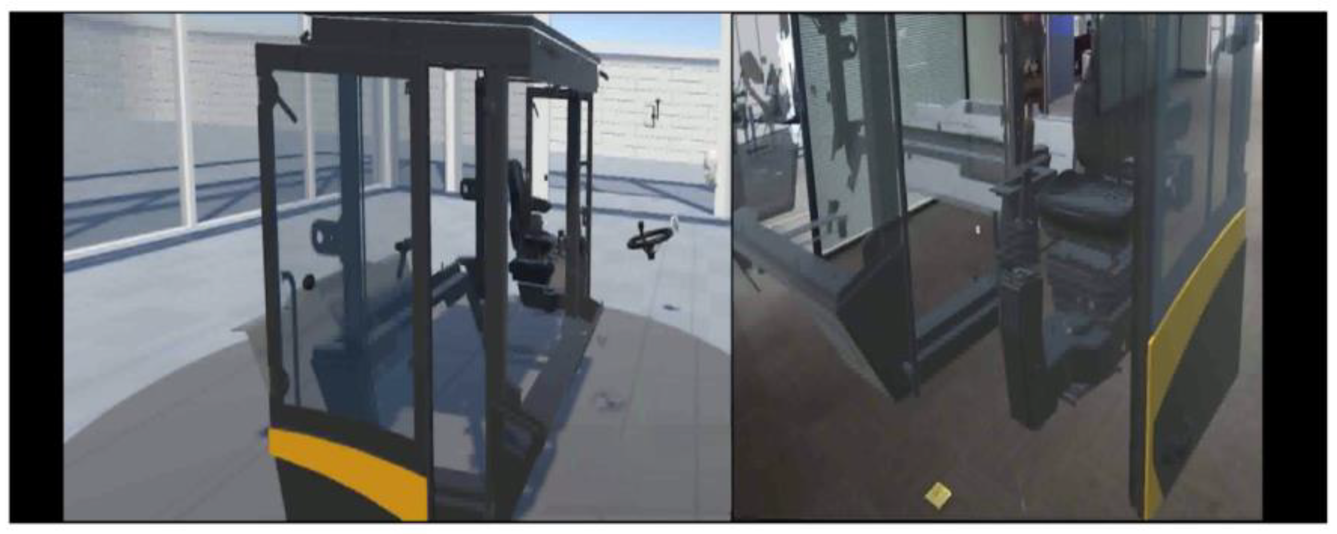
The MR device and VR device remote collaborative review cab design scheme is shown in
Figure 16. The left image shows the view of a designer wearing a VR device while the right image shows the view of a designer wearing an MR device. The VR device is fully immersive, excluding the influence of objects in the real world.
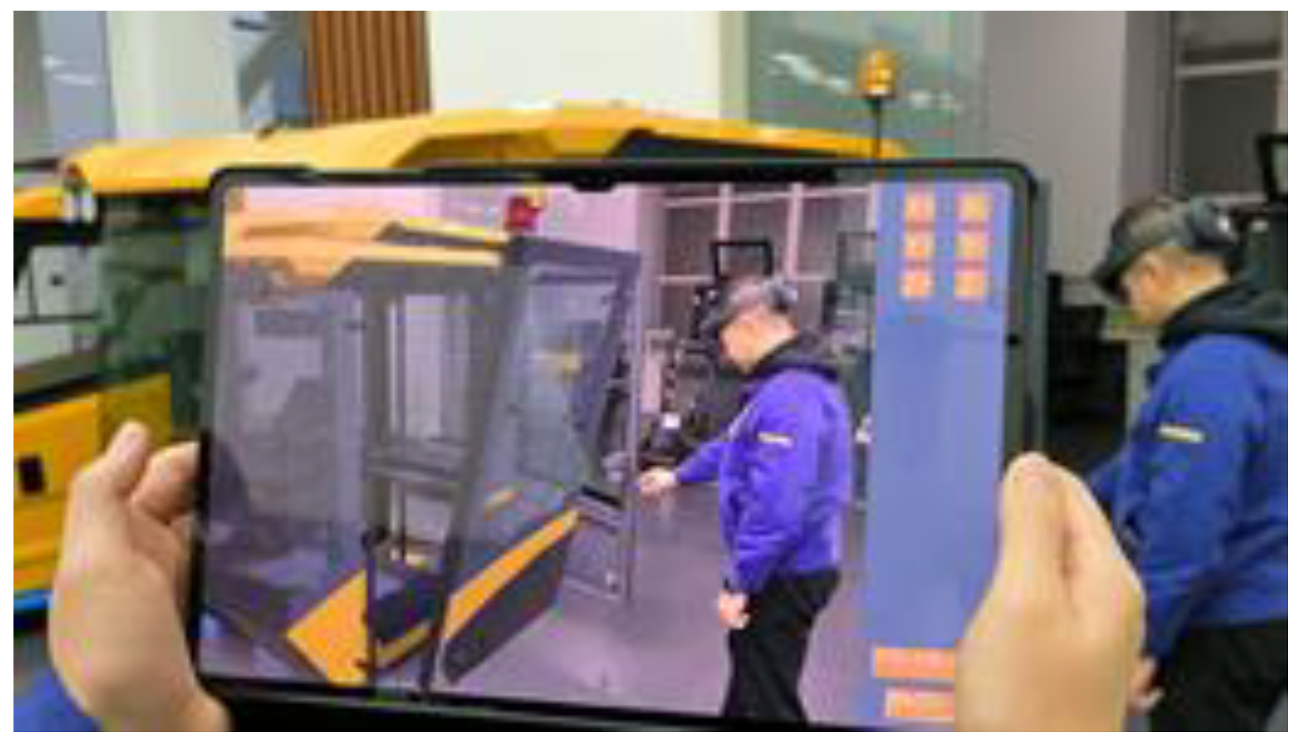
The MR device and mobile device collaborative review design solutions are shown in
Figure 17. This approach can also be referred to as a third-party perspective. A new and lightweight third-party view solution was designed in lieu of Microsoft’s Spectator View, where the designer wears the MR headset and virtual objects, as well as corresponding operations, can be observed in the mobile device. These can then be interacted with by simply touching virtual objects on the screen of the mobile device. In addition, the mobile device can be streamed live to the outside world with the help of a third-party pushing software.
The computing power of the MR device is relatively low, so when the user performs several operations, problems of delay and line drop may occur in the MR User’s scene. Therefore, to eliminate such problems as far as possible, a method is summarized based on the continuous testing site. In the current scene with the number of slices, when the user needs to synchronize the scene, the synchronization will be performed selectively.
Table 1 shows the time required by different multiple users to complete specific functions in the case of multiple objects.
4.3. Tractor Whole Machine Appearance Design Plan Review
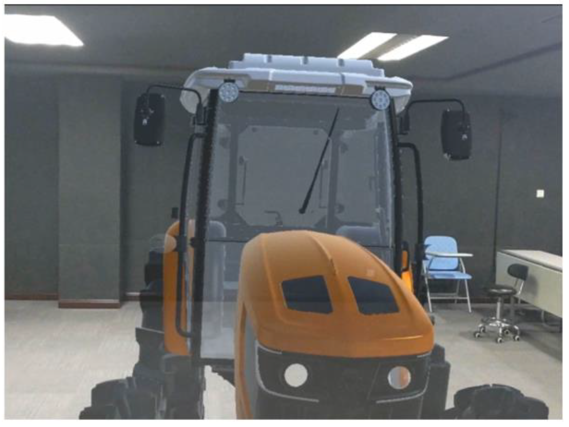
Appearance review in the R&D design stage is also very important and in the whole of the machine appearance review application. We can take making a virtual tractor machine as one example. Firstly, the MR Headset is worn to scan the environmental space and to select the plane on which the model needs to be placed. Then, the 3D tractor model is placed on a flat surface.
Figure 18 shows the virtual tractor model in the real environment.
As shown in
Figure 19, the review scheme has two toolboxes that can be chosen: the general toolbox (
Figure 19a) and the special toolbox (
Figure 19b). The toolbox buttons are expanded from left to right.
In the general toolbox, the wheel-package modeling and coating can be altered. As shown in
Figure 20, there are two wheel-package modeling schemes and three coating modeling schemes. When you select the special toolbox, you can switch various materials, paints, and colors, before selecting the corresponding part of the tractor you wish to alter. The material can also be loaded from the Asset Bundle in the cloud server. The ability to quickly combine different schemes is convenient for an efficient evaluation of the whole tractor shape.
When entering the cab, the measuring tool in the general toolbox can be opened and different measuring objects can be selected for dimensional measurement, including points, lines, and surfaces, as shown in
Figure 21. The scanning tool was selected and the model dissected.
Figure 22 shows the effect diagram after dissecting.
4.4. Factory Layout Verification of Milling Rotor Welding Line
The layout of the production line is one of the main elements of the factory’s arrangement. The factory needs to spend a lot of energy planning the layout of the production line before it is put into production. MR Technology is then used in the layout of the factory production line to obtain better results.
First, the location of the production line is determined in the factory, and the two-dimensional code is posted. Based on marker recognition technology, the MR headset can quickly locate and load the three-dimensional virtual model of the milling rotor welding production line into the scene. As shown in
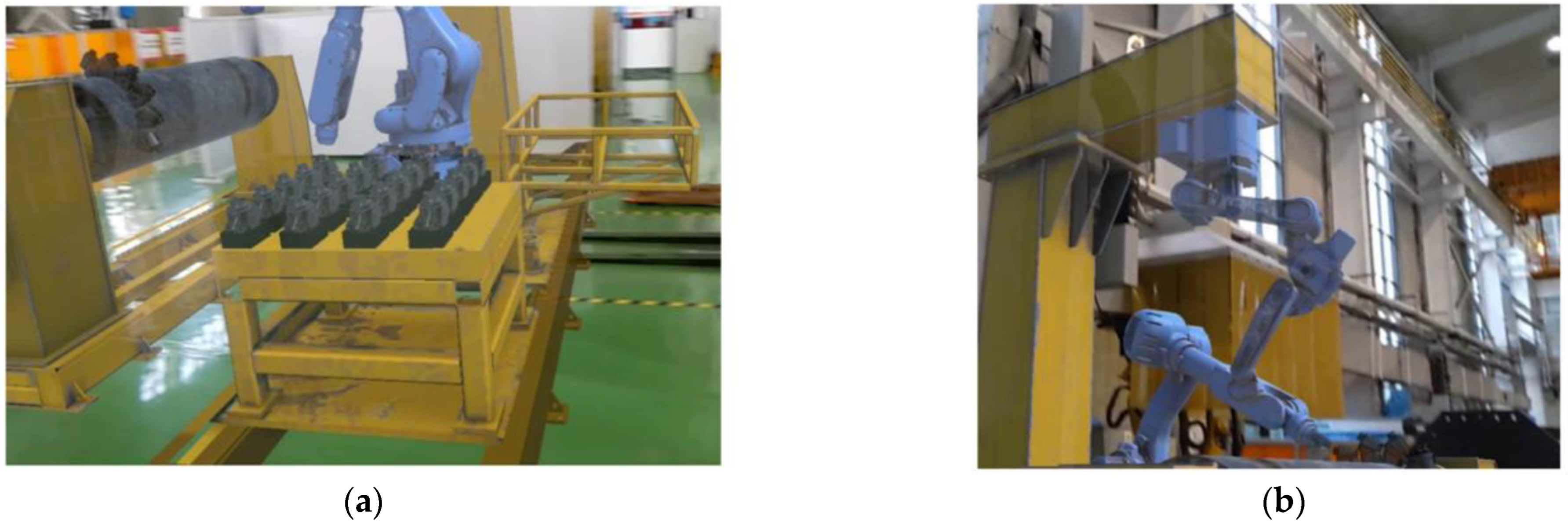
Figure 23, the position of the milling rotor welding production line has been completed. The designer can subsequently verify the reasonableness of the production line layout with the MR headset. The ability to use three-dimensional and immersive layouts are the main advantages over standard drawings. In addition, the virtual model simulates the operation of a production line, where a mechanical arm grabs the milling rotor onto the drum and welds it and the drum moves to the next welding position.
4.5. Milling Rotor Welding Process Digital Twin Visualization
This section takes the milling rotor welding production line as an example, building a digital twin-state monitoring system for cooperative robots. Firstly, the welding robot and the supporting construction facilities were modeled in equal proportions by field measurement and other methods, and the virtual sand table of the milling rotor welding production line was created. MR interactive control was used to control the presentation ratio of the virtual sand table.
Figure 24 shows the effect of the virtual sand table reduced in equal proportions in the MR head-mounted display.
In addition, a set of real-time synchronous mapping systems based on UDP communication and server-side twin data management is established. This opens the virtual and real remote wireless communication port, transferring the physical robot and drum state data to the twin in the virtual sand table in real-time. It then synchronizes the actual production line state with the production line state in the virtual sand table, checking the table’s state through the MR device. In this way, it can realize remote immersion monitoring of the milling rotor welding production line and support multi-person collaborative monitoring. The comparison between the actual production process of milling rotor welding and virtual mapping is shown in
Figure 25.
4.6. Construction Verification for Virtual Control of the High-Altitude Working Platform
This section introduces the construction verification case for the virtual control of the high-altitude working platform. The high-altitude working platform is shown in
Figure 26. The basic principle is to construct the virtual motion simulation mapping of the working platform and to experience its operation by wearing the MR headset, thereby realizing the real-time confirmation and training of complex on-site construction methods.
The movement of the high-altitude working platform is controlled by a wireless keyboard or control handle, the handle having a better operating experience.
Use W, A, S, and D on the keyboard to control the overall movement; use the up, down, left and right keys (↑, ↓, ←, →) to control the expansion and rotation of the long arm of the high-altitude working platform; use the J and L keys to control the rotation of the short arm; use the N and M keys to rotate the turntable;
The movement of the high-altitude operation platform is controlled by the up, down, left, and right keys of the control handle. The corresponding keys of the control handle for the operation of the boom system and the turntable are shown in
Figure 27. Press the “PgDn” key on the control handle to start the operation of the boom system. Corresponding keys 1 to 6 can select the corresponding lower main boom, lower telescopic boom, upper main boom, two upper telescopic booms, and working platform, respectively, and then carry out the corresponding rise “=“ and fall “-” operation. The “K” and “D” keys can rotate the turntable. The gamepad keys are shown in
Figure 26.
5. Discussion
This paper introduces a holographic visualization verification platform for digital prototype of construction machinery based on virtual terminal equipment, which is used to study the application of mixed reality technology in the manufacturing cycle of construction machinery. According to the observation results obtained from the case study, mixed reality technology contributes towards more efficient design, research and development verification, and helps intelligent manufacturing in factories. It therefore improves the user experience both in the process of promotion and use. Unlike the existing single MR application system framework [
2,
38,
39], the framework of this visual verification platform includes six modules. The six cases in this study correspond to these six modules, respectively, also corresponding to the four stages in the whole life cycle of construction machinery: design and development, production and manufacturing, sales and circulation, and user verification. The greatest contribution of this research, which focuses on the construction machinery industry, is to design a unique verification platform according to the actual industry scenarios and production processes.
5.1. Semi-Physical Virtual Assembly
Assembly assistance systems have always been the dominant research focus of MR technology, including assembly instruction, assembly guidance, interactive clues, etc. This paper also utilizes a special assembly assistant system to remind users of assembly sequence and assembly location. The previous auxiliary system can be used for assembly work of spacecraft modules, including assembly planning, assembly training and assembly quality inspection [
4]. Such MR guidance systems can also be used in factory assembly to automatically detect the position of equipment and targets [
23]. Previous studies have found that the HoloLens assist system works well [
40].
In the semi-physical virtual assembly module, combined with virtual-real integration technology, users can assemble virtual parts to the actual cab frame in the holographic environment. The virtual parts are dynamically loaded online through the server, aiming to complete the assembly verification and man-machine verification of construction machinery. Man-machine verification is one of the highlights of this paper. The virtual model of the cab is loaded onto the man-machine verification stand to verify the man-machine vision and accessibility of different cabs. Assembly verification and man-machine verification eliminate the dependence on the real vehicle in the design and development stage, meaning the verification of the design scheme can be completed through HMD, effectively shortening the research and development cycle.
The effect of semi-physical virtual assembly is more intuitive than that of complete virtual assembly. However, limited by the semi-physical frame, it can only complete specific assembly verification and man-machine verification. Next, it will be further promoted.
5.2. XR Remote Collaboration
Remote collaboration has been one of the fundamental applications of MR devices since Microsoft released the HoloLens2 as an expert remote guidance case. Researchers also have also offered different remote collaboration solutions. For example, a projector-based mixed reality remote collaboration system [
41]; a multi-person mixed reality application [
42], which supports remote participants to operate engineering equipment and learn operational processes in a shared virtual environment; and Snow Dome which support MR and VR user remote collaboration [
35].
Instead of extending an existing application to four different platforms— Steam VR, Microsoft mixed reality, smartphone, tablet, and desktop [
43]—the solution proposed in this paper is to share the same scene between MR, VR, and mobile terminals. Users can access servers based on requirements and actual conditions, sharing the same virtual scenario, and interacting with virtual objects.
Among the solutions designed in this study is the third-party perspective of MR-Mobile, which is lightweight, low-cost, and based on ARCore. Compared with Microsoft’s Spectator View, it is easier to build, and only needs a mobile device, mobile phone or tablet computer. Images captured by mobile devices can also be shared with the public through third-party streaming software, allowing more people to see the interaction between the real world and the virtual world in the holographic scene.
In MR–MR collaboration, users can see the relative positions of other people through virtual avatars but cannot realize this function in MR–VR collaboration, since the current VR device relies on access to a PC. In the future, it will be expanded to a VR all-in-one machine in order to realize this function.
5.3. Whole Machine Appearance Review
Like a traditional virtual appearance review, you can change the object by selecting the desired material in the material library, or selecting the parts in the styling library. Much like in a racing game, you can also change the color, styling, parts, and so on of the car according to your personal preference. This paper selects HoloLens2—the MR equipment currently recognized as having the best interactive effect—and creates a material library of 137 commonly used materials according to the characteristics of the construction machinery industry. The target users focus on the designers of the company. However, ordinary users can also have a better experience. The folding toolbox, for instance, is designed to better fit people’s usage habits. The general toolbox is used to switch materials, shapes, etc., and the special toolbox is used to host some small tools.
In the proposed appearance and shape evaluation scheme, some special tools are added, such as measurement and cutting. The measurement tool can measure the distance between any two points, lines, and surfaces, which is very practical for designers. The basic principle of the measurement tool is similar to the non-contact measurement method with interactive function proposed by Huang [
44]. Both are based on Microsoft’s mixed reality product HoloLens2. The depth camera on HoloLens is used to scan the measurement space. Measurement points are determined by using gaze and gesture functions that enable users to realize non-contact measurement and automatic calculation of distance between target points. The cutting tool allows the designer and the user to see the situation of the machine cross-section, thereby facilitating a better understanding of details.
5.4. Factory Layout Verification and Digital Twin Visualization
In order to minimize the cost of virtual objects and enhance the user’s sense of reality, MR technology is proposed to solve the layout problem of factory production lines. As early as 2011, Lee [
45] proposed a virtual factory layout planning system based on deploying the method of a mixed reality digital manufacturing environment. Similarly, MR technology is also applied to the layout of indoor furniture, where various three-dimensional computer graphics (such as sofas, beds and lamps) are superimposed on the real space, allowing users to visualize interior design [
46]. The factory layout works the same way as the interior layout, positioning virtual objects in the real world and observing the rationality of the layout with the help of an MR headset. The factory layout verification scheme proposed in this paper not only realizes the traditional production line layout, but also realizes the virtual production line simulation and simulates the real working environment. Considering the complexity of the actual production line, the current production simulation can only simulate routine operations, but cannot simulate the abnormal phenomenon such as equipment failure. MR tools are superior to traditional simulation software in terms of both planning quality and flexibility.
Digital twinning is a technology that maps virtual space to reflect the full life-cycle process of corresponding physical equipment. Digital twin technology in this paper is applied to the welding production process of milling rotors, this research is distinct from Buyruk’s [
47] digital twinning of parameterized design and robot manufacturing, which adding holographic content to images in the real world and superimposing them as holographic content. In this paper, with the help of MR remote collaboration technology, a mixed reality virtual sand table is constructed to transmit real-time parameters of equipment on the production line to the virtual sand table. The virtual sand table synchronizes data in real time and presents the simulation process of the production line in proportion, realizing remote monitoring through MR device. Compared with Zhou’s [
48] sand table prototype based on projection, the technology is simpler and the presentation effect is better.
5.5. Virtual Motion Simulation
The virtual motion simulation solution in this paper is inspired by the XE15R remote control hydraulic excavator, which is controlled by the handle. After analyzing the force and movement of complex moving parts, the function of complex construction machinery is modularized, and the movement components of engineering analytical solution are decomposed into: rocker (rocker hinge, rocker joint, rocker limit), crank (free crank, restricted crank), and slider (telescopic slider, sequential telescopic arm, connecting rod slider). The movement and rotation of each motion module are controlled by script to realize motion simulation. In this paper, common handles are selected to improve applicability and popularity.
In addition to the high-altitude working platform mentioned in this paper, the grader, the loader, etc., also realize virtual motion simulation. In the proposed virtual motion simulation method, users can realize the simulation operation of construction machinery without the real car. Compared with traditional PC simulation control, the immersion and control are the biggest advantages, which can not only be used for exhibition experience, but also for virtual training.
6. Conclusions and Future Work
With the rapid development of XR technology (VR, AR, and MR, etc.), its range of possible applications in an industrial environment have greatly expanded. Construction machinery is an important infrastructural tool within the field of equipment manufacturing. The application of MR technology in the manufacturing of construction machinery and equipment will help the development of traditional industries.
This paper proposes a holographic visualization verification platform for a digital prototype of construction machinery based on virtual terminal equipment. This equipment consists of six modules, including virtual-real integration design assembly verification and man-machine verification, remote multi-user collaborative review, complete machine modeling verification, factory production line layout, digital twin visualization of production line, virtual simulation and motion simulation of construction machinery equipment. The platform is designed to cover the whole life cycle of construction machinery. This study shows that the visual verification platform is a feasible, low-cost, and scalable solution that can be easily applied to the field of construction machinery. In addition, it not only expands the application of mixed reality technology in industrial fields, but also further advances intelligent manufacturing in traditional industries.
Further exploration of computer vision and machine learning techniques is needed to improve existing methods. For future research, the team will focus on optimizing the existing modules, developing more functional modules, and ameliorating the existing solutions using 3D reconstruction and data visualization technologies.


