Abstract
Manipulator motion planning for real-time obstacle avoidance in a dynamic environment is explored in this article. To address obstacle avoidance problems, a multiple-query and sampling-based motion replanning algorithm with the dynamic bias-goal factor, rapidly exploring random tree (DBG-RRT), is proposed to achieve a rapid response and a high success rate. Differently from other studies on path planning, a relay-node method is adopted on the basis of motion planning to generate a new collision-free trajectory. Subsequently, an un-interrupt strategy is embraced to judge whether the generated trajectory would be interfered with by dynamic obstacles. In the end, the DBG-RRT algorithm is applied, and the results demonstrate its effectiveness for manipulator motion planning in a dynamic environment.
1. Introduction
Autonomous robots are widely used for agriculture, manufacturing, aviation, etc. The intelligent factory is a man–machine hybrid system that has substantial economic benefits in production [1,2]. As for the robot, it is a significant challenge to work in a dynamic environment [3]. Obstacle avoidance methods require feasible solutions, such as processing information, data delivery, computational treatment, etc., within a stipulated period [4]. Especially in computational process, the collision is caused by unpredictable obstacles, e.g., operators appearing in the workspace with manipulators. Therefore, an efficient real-time planner is demanded in a dynamic environment, where the appearance, movement and disappearance of obstacles are not a priori conditions [5].
Path planning and trajectory planning are two types of tasks for the manipulator in the planning layer that typically generates an executable trajectory [6,7]. Once dynamic obstacles are affected while executing this trajectory, a new trajectory is planned to avoid the dynamic obstacles. Compared with the new trajectory, the initial trajectory is called as the previous trajectory. In this paper, a dynamic replanning frame and a dynamic bias-goal factor, rapidly exploring random tree (DBG-RRT) motion replanning algorithm, are introduced. In a static environment, the BG-RRT algorithm is efficient, and the dynamic strategy is introduced to support the robot in real-time replanning [8,9]. The proposed method does not distinguish between local and global planning, and gives priority to fast convergence to ensure a high success rate.
As for the sampling-based method, the RRT algorithm is widely used [10]. According to the characteristics of the RRT algorithm [11], different evolution algorithms are proposed to satisfy unpredictable or moving environments. Bruce et al. [12] proposed the execution extended RRT (ERRT) algorithm with efficient performance in mobile robots using the waypoint cache approach. Ferguson et al. [13] reused the previous path to propose a dynamic RRT (DRRT) algorithm. The new path grew to the root of the previous path. The RRT*FN dynamic (RRT*FND) algorithm was suggested by Adiyatov et al. [14]. The useful section of the extension tree was clipped and maintained, and the regrow and reconnect methods identified a new solution route. This strategy, however, would need some computations. Otte et al. [3] presented the RRT, which was an asymptotically optimal and single-query sampling-based motion replanning algorithm. The RRT algorithm respected the kinematics of the robot and was asymptotically optimal during navigation. Wen et al. [15] used the dueling DQN algorithm to solve the navigation under unknown environments, and the proposed algorithm had a good performance for autonomous navigation in a complex environment. Mao et al. [16] focused on task-restricted conflict resolution. They demonstrated an adaptive motion planning strategy for the manipulator to solve a variety of dynamic situations. Selin et al. [17] proposed frontier exploration planning as a global planner and best-view planning under the receding horizon as a local planner. The experimental results showed the proposed method can quickly explore large unknown environments without falling into a local minimum.
The DBG-RRT algorithm, which is a multiple-query sampling-based motion replanning algorithm, is proposed to provide a high success rate and stable performance in dynamic environments. The main contributions are concluded as follows:
- In order to move continuously in dynamic environments, the concept of a relay node based on motion planning is introduced to generate a new no-collision trajectory according to the position, robot’s velocity, and the predicted velocity of moving obstacles.
- The connection strategy is designed with the reconnect, regrow, and un-interrupt strategy to make up all possible replanning cases and fix the interrupted planning in dynamic obstacle avoidance.
- The DBG-RRT algorithm is proposed based on KD-tree and the waypoint cache method, and is verified with a robust performance by the dynamic obstacle-avoidance simulation platform and experiment platform.
The remaining parts are organized as follows. The dynamic obstacle-avoidance issue and notation are described in Section 2. Section 3 introduces the background of the BG-RRT algorithm and motion planning. The relay-node method and dynamic strategy are proposed in Section 4. Section 5 performs the simulation platform and experiment platform to verify the DBG-RRT algorithm. Finally, the conclusion is offered in Section 6.
2. Environment and Notation
2.1. Environment
Obstacle-avoidance planning is separated into two types based on motion planning: static environment and dynamic environment. Moreover, the obstacle-avoidance planning in a dynamic environment includes known environments and unknown or partially unknown environments, as shown in Figure 1. When the environment or target changes, a new trajectory is replanned during the movement. The new trajectory and previous trajectory are connected smoothly, and the robot moves continuously.

Figure 1.
Classification of obstacle-avoidance planning.
Set a stationary and known prior obstacle set as in static environments. In addition, set a dynamic obstacle set as , where t is time. As for the dynamic obstacles with uncertain moving, it is hard to anticipate the dynamic obstacles [18]. Based on the probability theory, the uncertainty modeling of dynamic obstacles is carried out to anticipate the change of information of dynamic obstacles including their speed and motion direction in the workspace, and is depicted in reference [19].
2.2. Notation
The path planning concretes on a geometric path in a configuration space. Considering the time constraints of the dynamic obstacle and trajectory planning, the state of obstacle avoidance problem is set in a configuration space with time constraint as , where [16]. Therefore, . All the obstacles are configured as . Thus, the free region of obstacles is set as that the robot can reach. Set the extension tree embedded in S, where N, V, and E are the nodes of the extension tree set, the vertices of the path set, and the edge set, respectively. Set the vertices of the path as , where is the discrete function from the start time to the end time . An execution trajectory is created by the robot’s kinodynamic and other constraints, e.g., maximum acceleration. The start state and the goal state both belong to V. Set is a Euclidean distance function on S, and all .
3. Background: BG-RRT Algorithm and Motion Planning
In this section, the BG-RRT algorithm, which takes the idea of potential field and heuristic probability, is introduced to satisfy the need for real-time dynamic planning. Furthermore, the rarefy treatment and non-uniform B-spline interpolation is used to generate a smooth execution trajectory [8].
3.1. BG-RRT
The BG-RRT algorithm is proposed by the extension approach according to the heuristic idea based on the well-known RRT algorithm [20]. As for the RRT algorithm, is defined as
where is the step size; and are randomly sampled points and the points closest to in . The bias-goal factor is used to update the sampling method according to reference [8] in Figure 2. Thus, combined with is reconfigured as
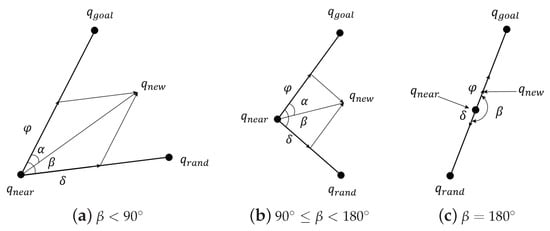
Figure 2.
Three cases sampled by the BG-RRT algorithm.
is set as
where x is . and are the indeterminate coefficients.
Although the BG-RRT algorithm introduces the potential field idea, it converges quickly with a high success rate while avoiding the local minimum problem in complex environments.
3.2. Motion Planning
Trajectory planning is an important part of manipulator motion planning and the basis of trajectory-tracking control, as shown in Figure 3. Trajectory planning uses path points to generate a smooth trajectory execution, e.g., minimum snap optimization [21], B-spline trajectory optimization [22], kinodynamic constraints [23,24], etc. Considering the non-uniformity of the waypoint, a non-uniform B-spline method is adopted to fit the discrete waypoints to generate the executable trajectory for manipulator. The specific process is described in reference [8]. As shown in Figure 4, the trajectory planning is realized on the path points, which are plotted with green, after the rarefying by the Douglas–Peucker algorithm. The red path represents the connection of waypoints planned by the BG-RRT algorithm. The green waypoints are the rarefied paths by the Douglas–Peucker algorithm lined with blue. The cyan continuous trajectory is an executable trajectory generated by the non-uniform B-spline method.
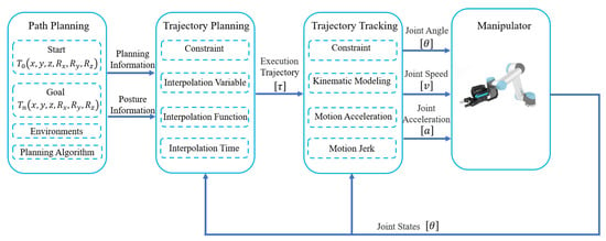
Figure 3.
Manipulator motion planning control.
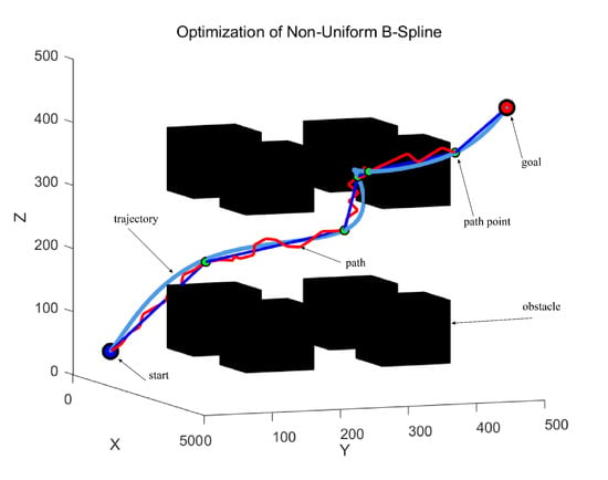
Figure 4.
Three paths are generated in the motion planning.
4. Dynamic BG-RRT Motion Replanning
Based on reference [19], the DBG-RRT motion replanning algorithm, which includes the relay-node method, connection strategy, and un-interrupt strategy, named according to how the tree expands and based on sampling, is proposed for manipulators to solve the obstacle avoidance planning problem. Furthermore, the KD-tree [25] and waypoint cache [26] methods are introduced to improve searching speed and efficiency.
4.1. Obstacle Avoidance Problem Description
In the process of dynamic obstacle avoidance, the manipulator needs to replan according to the updated environment. Dynamic environments are different from static environments, but they can generally be regarded as real-world updates alternating with the system of planner [18]. Therefore, the processes of dynamic obstacle avoidance are summarized in Figure 5.
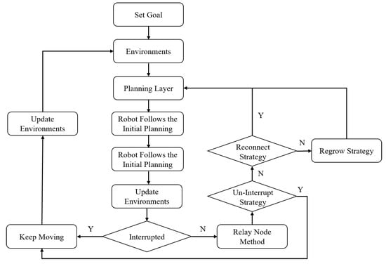
Figure 5.
The flowchart of the obstacle-avoidance problem.
4.2. Relay Node
In order to meet the real-time needs of manipulators working in unknown environments, the relay-node method, which generates a collision position according to the motion state of dynamic obstacles and the robot, is proposed. When the initial planning is blocked, is calculated according to the information on robot and dynamic obstacles. In the process of moving to , a new trajectory is repaired in the updated environment. If the robot fails to repair before reaching the , it will stop and wait until planning is complete. If the robot is affected by dynamic obstacles continuously during the motion, it will recalculate according to the current execution trajectory and repeat the above process to complete the task.
The relay-node method based on path planning is described as shown in Figure 6. The red nodes and yellow nodes represent the V and . The robot’s current position is set as , thus, is the angle between the direction of the obstacle and the line from the robot to the current position of obstacles. Set the velocity of robot as , and assume that the robot always moves along with initial planning with the maximum velocity . In this way, the replanning is safe according the than . The velocity and motion angle of dynamic obstacles are set as and , respectively, where the and are configured according to the dynamic obstacle of uncertain expression by the probability theory. Set the position where the boundary of dynamic obstacle intersects the initial planning, also near to as . Recording the sequence of path points, the is calculated by the binary search BinarySearch(). Therefore, the relay-node based on path planning in reference [19] is defined as , where the k is configured as:
where is the distance between and . in Equation (4) is much safer than is calculated on the line between and .
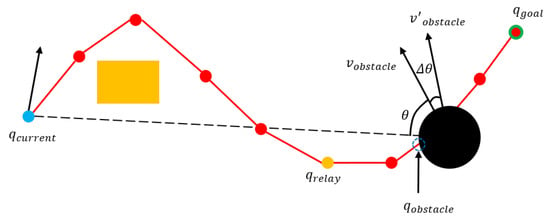
Figure 6.
Schematic diagram of the relay-node method based on path planning.
Compared with the limited nodes in path planning, the motion trajectory is more accurate to represent the position of relay node. The dynamic obstacle avoidance problem needs to solve based on motion planning for the manipulator or other robots. As shown in Figure 7, the position of is a defined by summing along the execution trajectory as , where the k is identical with Equation (4). Compared to the above methods, the description of based on motion planning is more accurate. At the same time, the calculation of the binary search method is avoided and the success rate is improved.
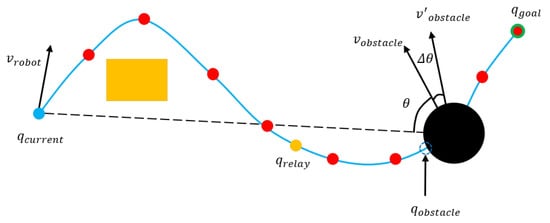
Figure 7.
Schematic diagram of the relay-node method based on motion planning.
4.3. Connection Strategy
The connection strategy is implemented based on reference [14] by the relay-node approach. According to the extended mode of RRT tree, the connection strategy is divided into the reconnect strategy, regrow strategy, and un-interrupt strategy.
When the initial planning is disrupted by dynamic obstacles, the cache information of the searching tree is reused. If the failure planning is repaired before the robot arrives at , it will move continuously through to execute the repaired planning. Otherwise, the robot will come to a halt until the problem is resolved.
4.3.1. Reconnect
According to the repair method of the RRT, the failure tree is connected again by a straight line with a single step. The above replanning strategy is defined as the reconnect strategy. As shown in Figure 8a, the robot moves along with the initial planning, the blue dotted line represents the execution trajectory. When dynamic obstacles interrupt the previous planning, the failed V is removed. The path points are divided by the dynamic obstacle as the valid path node and the backward path node (the subscripts are named according to the parent–child relationship in initial planning), and is calculated as shown in Figure 8b. The vicinity node of and are inquired to repair the failure planning in a single step within a range of the center and the radius r, as shown in Figure 8c. and are selected form and . If the solution is found, the points from and are directly connected to repair the planning, as shown in Figure 8d.
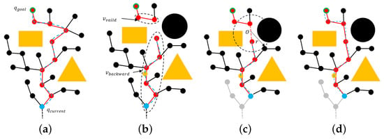
Figure 8.
The strategy of Reconnect.
4.3.2. Regrow
As for the unpredictability of dynamic impediments, once the failure tree cannot be repaired by the reconnect strategy, the regrow strategy, which makes full use of cache information, is introduced to repair the failure planning. In Figure 9a, the robot moves along with the initial planning similar to Figure 8a. As shown in Figure 9b, is calculated, and only considers the end of T between and to find the lowest cost node as new which is plotted with black with a blue circle, as shown in Figure 9c. Then, the is set as a new . It is not necessary, states reference [13], to compulsive repair toward the root of . Within the error range, T will extend to any node in in Figure 9d. The BG-RRT algorithm is implemented in this step to accelerate the convergence speed.
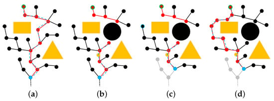
Figure 9.
The strategy of Regrow.
4.4. Un-Interrupt
Although the previous planning is interrupted by movement obstacles, the robot, which continues to move along with the initial planning, may not collide with the obstacle because the dynamic obstacle moves away from robot or exceeds the collision range of the robot. Compared with the replanning execution, the robot has more obvious advantages to executing the previous planning. Therefore, a new strategy named un-interrupt is proposed with full consideration of the uncertainty of dynamic obstacles to judge whether the previous planning is still blocked when the robot arrives at the .
There are three cases, as shown in Figure 10. If the robot arrives at the , and the obstacle is also interrupted by the planning, it means the dynamic obstacle always influences the solution, as shown in Figure 10a,c. Otherwise, the dynamic obstacle is considered as moving away in Figure 10b. Hence, the robot can continue to move along with the previous planning.

Figure 10.
The strategy of un-Interrupt.
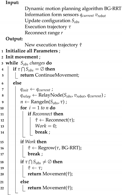
The pseudo-code of the DBG-RRT algorithm is provided in Algorithm 1. Three strategies are counted with six different sizes of the dynamic obstacle, which is 30∼300% of the static obstacles’ size, in random motion for 1000 times each group, as shown in Figure 11. The characteristic of the strategy is concluded as follows:
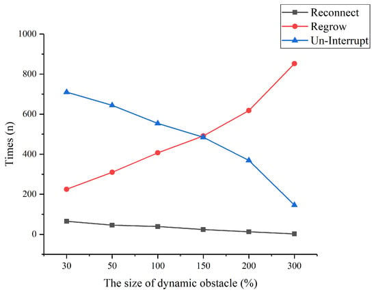
Figure 11.
The time of three strategies in 1000 trials.
- The number of the reconnect strategy is much smaller than the others. Furthermore, the reconnect strategy is the first step of the connection strategy, and it works in the condition changed by a small size obstacle. Little computation is taken by checking the points in the area of r.
- The BG-RRT algorithm is better combined with the regrow strategy in experiments, and the regrow strategy takes part mainly in replanning. To improve efficiency, the waypoint cache method is introduced in the regrow strategy.
- Because of the and the un-interrupt strategy, the robot can continue to follow the previous trajectory. Both sides are indispensable, and the un-interrupt strategy based on the is essential.
- The choice of strategy is greatly influenced by the obstacle configuration. With the increase in dynamic obstacle size, the regrow strategy is more efficient than the un-interrupt strategy. However, both of them can help solve the uncertainty dynamic obstacle-avoidance problem.
| Algorithm 1: DBG-RRT |
 |
5. Experiment
The dynamic obstacle-avoidance simulation platform and experiment platform are built based on the collaborative manipulator with Intel Core i5-8265U 1.8 GHz and 8 GB computer to verify the DBG-RRT algorithm. The probability towards the goal and waypoint are set as and [12].
5.1. Simulation-Platform
The BG-RRT algorithm is inherited by C++ in ompl::base::planner to evaluate the efficiency of the proposed method in the simulation platform. The dynamic obstacle avoidance strategy is encapsulated as a ROS node to move_group interface. According to the uncertainty modeling [19], the function under the moveit_msgs class is used to plan the dynamic obstacle.
The manipulator works in complex environments that include stationary obstacles and dynamic obstacles. Thus, the environments are set, as shown in Figure 12, compared with the ERRT algorithm [12] and the DRRT algorithm [13] to test the efficiency of the DBG-RRT algorithm with 100 simulation times in each map, as shown in Table 1. The difficulty of replanning from the map in Figure 12a to the map in Figure 12c is increasing. Although there are more obstacles in Figure 12b, the process of replanning is relatively simple. To experiment clearly, the manipulator’s maximum speed and maximum acceleration are restricted to 30%. In addition, when the target is met, a one-second pause is established to indicate manipulator operation.

Figure 12.
Experiment maps. In the workspace of the manipulator, (a) has no static obstacles, (b) has three static tables, and (c) has a static table. The start point is plotted in green, and the goal point is plotted in red.

Table 1.
The experiment data to test dynamic strategy.
As shown in Table 1, the ERRT algorithm does not perform well, because the waypoint cache method of the ERRT algorithm may directly grow to the goal with obstruction. That makes the ERRT algorithm cost a lot at some time. As for the manipulator, which has a complex joint space, the DRRT algorithm has a slower response, because of the replanning distance more than the DBG-RRT algorithm.The DBG-RRT algorithm maintains a high success rate in more complex environments. At the same time, the BG-RRT algorithm can also enhance the success rate. Therefore, the DBG-RRT algorithm has distinct advantages over other dynamic algorithms.
The manipulator behavior is separated into six phases in Figure 13, once complete manipulator dynamic obstacle avoidance from the start to the objective has begun and next to the start in Map 3. In the beginning, the green dynamic obstacle is emerging in a manipulator workspace. In Figure 13b, the manipulator begins to execute the initial planning, and the dynamic obstacle is changing position. If the manipulator travels along the intended planning with the cyan line as depicted in Figure 13c, it will collide with the dynamic obstacle. Then, a new trajectory is planned, and the manipulator moves along with it, as shown in Figure 13d. After that, the manipulator arrives at the goal in Figure 13e and plans a trajectory to the start position in Figure 13f. As shown in Figure 14, the movement of the manipulator is gentle, and there is no abrupt change in the process of obstacle avoidance, plotted as . The manipulator’s joints move smoothly during obstacle avoidance.
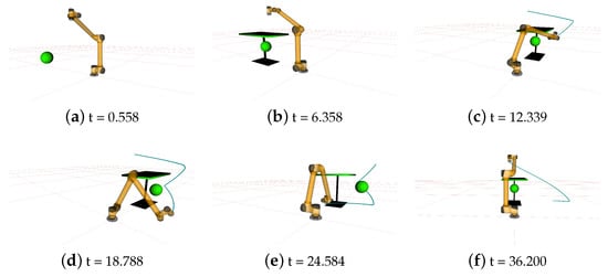
Figure 13.
The simulation in Map 3.
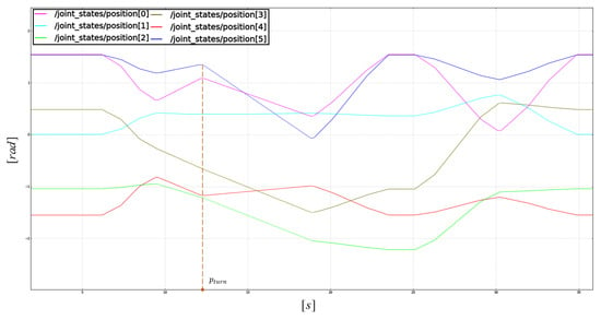
Figure 14.
Changes in each joint of dynamic motion planning in Map 3.
5.2. Experiment-Platform
The dynamic obstacle avoidance experiment-platform is built with a real manipulator, Kinect V2 RGB-D sensor, etc. The manipulator motion is impacted by manual operation connecting the rod. Furthermore, the maximum speed and maximum acceleration of manipulator are limited to 50%, and the experimental arrangement is set, as shown in Figure 15, which includes the Aubo-i5 manipulator, static obstacles, and Kinect sensor. The key positions of the manipulator in different scenes are shown in Table 2.
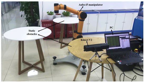
Figure 15.
The arrangement of experiment-platform.

Table 2.
The pose of key points for manipulator in different scenes.
5.2.1. Scene 1
Figure 16 is the whole process, which is similar to Map 3 in the dynamic obstacle avoidance experiment. Dynamic obstacles are artificially set to interrupt the manipulator motion. Figure 16a is the initial position of the manipulator when the collision is detected by the RGB-D sensor of Kinect V2, which is monitoring the manipulator workspace, as shown in Figure 16b. The manipulator is replanned according to the current environment information, as shown in Figure 16c,d. After that, the manipulator moves continuously and reaches the goal position accurately after replanning the trajectory in Figure 16e. The initial planning trajectory and the replanning trajectory of the manipulator are marked with red and blue lines, respectively, in Figure 16f. It is evident that the proposed strategy, rather than replanning to the desired location, uses cache information to fix the trajectory.
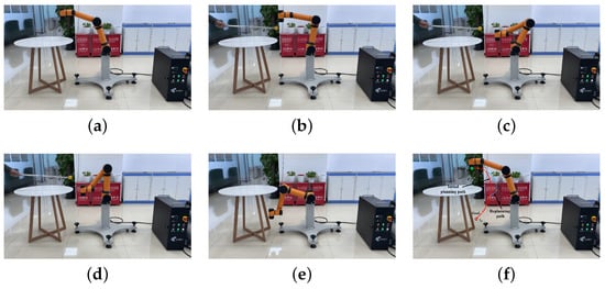
Figure 16.
The experiment in Map 3.
5.2.2. Scene 2
The manipulator in Scene 2 is affected by multiple dynamic obstacles during the manipulator movement. Figure 17a is the start position. In the process of manipulator movement, the RGB-D sensor detects that the dynamic obstacle is affecting the execution trajectory, as shown in Figure 17b. The manipulator replans and avoids the dynamic obstacle, as shown in Figure 17c. Figure 17d depicts that the manipulator accurately reaches the middle position according to the updated environments after avoiding the dynamic obstacle. After one second pause, the manipulator is planned and carried out to the goal position, as shown in Figure 17e, and is also affected by dynamic obstacles in Figure 17f. Finally, the manipulator avoids obstacles and reaches the goal position in Figure 17g. The initial planning trajectory and the replanning trajectory of manipulator are marked with red and blue lines, respectively, in Figure 17h. The validity of DBG-RRT algorithm affected by multiple dynamic obstacles is proved. In addition, Figure 17f,h are marked with the time stamp of key positions as shown in Table 3.
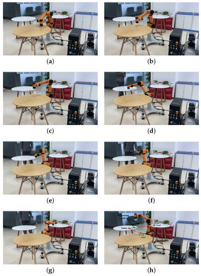
Figure 17.
The experiment in Map 2.

Table 3.
The key position of time stamps for manipulator in three scenes.
6. Conclusions
Several enhancements have been implemented to increase real-time planning and success rates for manipulator motion planning in dynamic situations. With a high success rate and quick reaction, the DBG-RRT motion replanning algorithm is presented, based on the relay-node approach. Compared with path planning, the relay-node approach for motion planning generates a new improved no-collision trajectory before the prior solution is fixed. In addition, the relay-node approach allots enough computation time to fix a path by the connection strategy, including the reconnect strategy, regrow strategy, and un-interrupt strategy. The un-interrupt strategy, which is based on the relay-node approach, is made up of other strategies to make the dynamic strategy more complete. According to simulations and studies in ROS, the DBG-RRT algorithm performs well in both static and dynamic environments.
In the future, in order to further simulate the working conditions in a smart factory, we will focus on multiple manipulators for cooperative work in obstacle avoidance. The multi-sensor fusion technology will be combined to build environmental information together.
Author Contributions
Conceptualization and writing—original draft, C.Y.; data curation and validation, C.Y.; writing—review & editing, C.S. and W.Z.; formal analysis and software, C.Y.; supervision and software, C.Y. All authors have read and agreed to the published version of the manuscript.
Funding
This work is not funded and supported by any organization.
Institutional Review Board Statement
Not applicable.
Informed Consent Statement
Not applicable.
Data Availability Statement
Not applicable.
Conflicts of Interest
The authors declare no conflict of interest.
References
- Wei, K.; Ren, B. A method on dynamic path planning for robotic manipulator autonomous obstacle avoidance based on an improved RRT algorithm. Sensors 2018, 18, 571. [Google Scholar] [CrossRef] [PubMed]
- Savazzi, S.; Rampa, V.; Spagnolini, U. Wireless cloud networks for the factory of things: Connectivity modeling and layout design. IEEE Internet Things J. 2014, 1, 180–195. [Google Scholar] [CrossRef]
- Otte, M.; Frazzoli, E. RRTX: Asymptotically optimal single-query sampling-based motion planning with quick replanning. Int. J. Robot. Res. 2016, 35, 797–822. [Google Scholar] [CrossRef]
- Desai, A.; Collins, M.; Michael, N. Efficient Kinodynamic Multi-Robot Replanning in Known Workspaces. In Proceedings of the 2019 International Conference on Robotics and Automation (ICRA), Montreal, QC, Canada, 20–24 May 2019; pp. 1021–1027. [Google Scholar]
- Faridi, A.Q.; Sharma, S.; Shukla, A.; Tiwari, R.; Dhar, J. Multi-robot multi-target dynamic path planning using artificial bee colony and evolutionary programming in unknown environment. Intell. Serv. Robot. 2018, 11, 171–186. [Google Scholar] [CrossRef]
- Sun, Y.; Zhang, C.; Sun, P.; Liu, C. Safe and Smooth Motion Planning for Mecanum-Wheeled Robot Using Improved RRT and Cubic Spline. Arab. J. Sci. Eng. 2019, 45, 3075–3090. [Google Scholar] [CrossRef]
- Gia Luan, P.; Thinh, N.T. Real-time hybrid navigation system-based path planning and obstacle avoidance for mobile robots. Appl. Sci. 2020, 10, 3355. [Google Scholar] [CrossRef]
- Yuan, C.; Zhang, W.; Liu, G.; Pan, X.; Liu, X. A Heuristic Rapidly-Exploring Random Trees Method for Manipulator Motion Planning. IEEE Access 2019, 8, 900–910. [Google Scholar] [CrossRef]
- Wang, C.; Zhang, Q.; Tian, Q.; Li, S.; Wang, X.; Lane, D.; Petillot, Y.; Wang, S. Learning mobile manipulation through deep reinforcement learning. Sensors 2020, 20, 939. [Google Scholar] [CrossRef] [PubMed]
- Zhang, Z.; Qiao, B.; Zhao, W.; Chen, X. A Predictive Path Planning Algorithm for Mobile Robot in Dynamic Environments Based on Rapidly Exploring Random Tree. Arab. J. Sci. Eng. 2021, 46, 8223–8232. [Google Scholar] [CrossRef]
- He, Z.; He, Y.; Zeng, B. Obstacle avoidance path planning for robot arm based on mixed algorithm of artificial potential field method and RRT. Ind. Eng. J. 2017, 20, 56–63. [Google Scholar]
- Bruce, J.; Veloso, M.M. Real-time randomized path planning for robot navigation. In Proceedings of the IEEE/RSJ International Conference on Intelligent Robots and Systems, Lausanne, Switzerland, 30 September–4 October 2002; Springer: Berlin/Heidelberg, Germany, 2002; pp. 288–295. [Google Scholar]
- Ferguson, D.; Kalra, N.; Stentz, A. Replanning with rrts. In Proceedings of the 2006 IEEE International Conference on Robotics and Automation, ICRA 2006, Orlando, FL, USA, 15–19 May 2006; pp. 1243–1248. [Google Scholar]
- Adiyatov, O.; Varol, H.A. A novel RRT*-based algorithm for motion planning in dynamic environments. In Proceedings of the 2017 IEEE International Conference on Mechatronics and Automation (ICMA), Takamatsu, Japan, 6–9 August 2017; pp. 1416–1421. [Google Scholar]
- Wen, S.; Zhao, Y.; Yuan, X.; Wang, Z.; Zhang, D.; Manfredi, L. Path planning for active SLAM based on deep reinforcement learning under unknown environments. Intell. Serv. Robot. 2020, 13, 263–272. [Google Scholar] [CrossRef]
- Mao, H.; Xiao, J. Real-Time Conflict Resolution of Task-Constrained Manipulator Motion in Unforeseen Dynamic Environments. IEEE Trans. Robot. 2019, 35, 1276–1283. [Google Scholar] [CrossRef]
- Selin, M.; Tiger, M.; Duberg, D.; Heintz, F.; Jensfelt, P. Efficient autonomous exploration planning of large-scale 3-d environments. IEEE Robot. Autom. Lett. 2019, 4, 1699–1706. [Google Scholar] [CrossRef]
- Du Toit, N.E.; Burdick, J.W. Robot motion planning in dynamic, uncertain environments. IEEE Trans. Robot. 2011, 28, 101–115. [Google Scholar] [CrossRef]
- Yuan, C.; Liu, G.; Zhang, W.; Pan, X. An efficient RRT cache method in dynamic environments for path planning. Robot. Auton. Syst. 2020, 131, 103595. [Google Scholar] [CrossRef]
- LaValle, S.M. Rapidly-Exploring Random Trees: A New Tool for Path Planning; Iowa State University: Ames, IA, USA, 1998. [Google Scholar]
- Richter, C.; Bry, A.; Roy, N. Polynomial trajectory planning for aggressive quadrotor flight in dense indoor environments. In Robotics Research; Springer: Berlin/Heidelberg, Germany, 2016; pp. 649–666. [Google Scholar]
- Stoican, F.; Prodan, I.; Popescu, D.; Ichim, L. Constrained trajectory generation for uav systems using a b-spline parametrization. In Proceedings of the 2017 25th Mediterranean Conference on Control and Automation (MED), Valletta, Malta, 3–6 July 2017; pp. 613–618. [Google Scholar]
- Campos-Macías, L.; Gómez-Gutiérrez, D.; Aldana-López, R.; de la Guardia, R.; Parra-Vilchis, J.I. A hybrid method for online trajectory planning of mobile robots in cluttered environments. IEEE Robot. Autom. Lett. 2017, 2, 935–942. [Google Scholar] [CrossRef]
- Yuan, C.; Shuai, C.; Ma, J.; Fang, Y. An efficient control allocation algorithm for over-actuated AUVs trajectory tracking with fault-tolerant control. Ocean Eng. 2023, 273, 113976. [Google Scholar] [CrossRef]
- Wu, X. Research on Dynamic Motion Planning for Manipulator among Movable Obstacles. Master’s Thesis, Zhejiang University, Hangzhou, China, 2019. [Google Scholar]
- Liu, C.; Han, J.; An, K. Dynamic Path Planning Based on an Improved RRT Algorithm for RoboCup Robot. Robot 2017, 39, 8–15. [Google Scholar]
Disclaimer/Publisher’s Note: The statements, opinions and data contained in all publications are solely those of the individual author(s) and contributor(s) and not of MDPI and/or the editor(s). MDPI and/or the editor(s) disclaim responsibility for any injury to people or property resulting from any ideas, methods, instructions or products referred to in the content. |
© 2023 by the authors. Licensee MDPI, Basel, Switzerland. This article is an open access article distributed under the terms and conditions of the Creative Commons Attribution (CC BY) license (https://creativecommons.org/licenses/by/4.0/).