Article

Case Study and Risk Assessment of Water Inrush Disaster in Qingdao Metro Line 4

1
School of Civil Engineering, Qingdao University of Technology, Qingdao 266520, China
2
Department of Civil and Environmental Engineering, Brunel University London, London UB8 3PH, UK
3
Engineering Research Center of Concrete Technology under Marine Environment, Ministry of Education, Qingdao 266520, China
*
Author to whom correspondence should be addressed.
Appl. Sci. 2023, 13(6), 3384; https://doi.org/10.3390/app13063384
Submission received: 16 February 2023 / Revised: 4 March 2023 / Accepted: 5 March 2023 / Published: 7 March 2023
(This article belongs to the Special Issue Fracture and Failure of Jointed Rock Mass)

Abstract

:
Water inrush is one of the most frequent and catastrophic hazards in tunnel engineering, and poses serious threats to the safety of engineering and personnel. This paper presents a case study of a water inrush and ground collapse in the Qingdao Metro Line 4, which caused a cave-in with the diameter and depth of about 30 m and 6 m, respectively. Based on the field data and numerical modelling, the causes of the disaster were analyzed. A numerical model was used to analyze the changes of surface settlement, vault settlement and water pressure during the tunnel excavation. The results of the study indicate that the cause of this disaster was the failure of the tunnel vault surrounding rock caused by the weakening of the tunnel surrounding rock and water pressure, which in turn triggered the water inrush in the tunnel and caused a large volume of surface collapse. As the tunnel was excavated from the slightly weathered area to the strongly weathered area, the vault settlement increased, and the influence zone expanded towards the surface due to the continuous decrease in the strength of the surrounding rock. In particular, a negative pore water pressure zone was formed in a certain area around the tunnel during the water inrush. The negative pressure zone caused the surrounding groundwater to converge here, leading to an increase in the amount of water inflow, which also increased the scope and scale of the impact of this disaster. A risk assessment method for water inrush in tunnels is proposed. According to the geological and engineering characteristics of Qingdao area, the evaluation index system of tunnel water inrush risk was established. An RBF neural network was improved by gray correlation analysis and a PAM clustering algorithm to establish the tunnel water inrush risk assessment model. Comparing the evaluation data with the actual data, the prediction data of a traditional RBF neural network and a BP neural network, the accuracy and reliability of the model were verified. This study has value in reducing the occurrence of water inrush in a composite formation tunnel.

1. Introduction

As metro construction increases, the pressure of urban surface transportation brought about by urban development and dense population has been greatly alleviated, and metro is the preferred transport mode of people [1,2]. According to statistics from the National Bureau of Statistics, 51 cities in China had opened metro lines by the end of 2021, with a total operating distance of 8736 km. However, water inrush disasters often occur due to geological and groundwater during metro tunnel construction [3]. For example, on 6 May 2011, a water inrush accident occurred during the construction of Tianjin Metro Line 2, and caused the collapse of the road surface. Another example is that on 7 February 2018, in Foshan Metro Line 2, when a water inrush accident occurred and caused the tunnel and roadway to collapse. Water inrush disasters not only cause life and property loss, but also cause environmental problems such as surface collapse and groundwater loss [4]. Therefore, reducing the occurrence of water inrush is of great significance for safe construction, property loss and environmental protection.
Various methods, such modeling experiments, numerical simulation and field tests have been adopted to explain the mechanism of water inrush. In terms of modeling experiments, various types of models with different sizes and conditions have been proposed to study the process of water inrush. For instance, Li et al. [5] studied the stability of the surrounding rock using a true triaxial geological model test, revealed the internal connections between physical information such as displacement, stress and seepage pressure during tunnel excavation, and established the theoretical basis of the predicting of water inrush. Yang et al. [6] proposed a 3D fluid-solid coupling model test to study the evolution process of water inrush caused by excavation and rainfall, and revealed the mechanism of water inrush. Zhou et al. [7] carried out a seepage instability water inrush test of a karst pipeline to study the evolution process of the filling material seepage instability water inrush and analyzed the changes of surrounding rock displacement, stress, and seepage pressure during the water inrush process. Wang et al. [8] developed a visual experimental system of particle migration to study the mass loss evolution of broken porous rock induced by seepage failure, and discussed the influence of grain gradation on particle migration. However, experimental research is restricted by models without real geological conditions, resulting in difficulty to truly deduce the evolution process of water inrush disaster in engineering. With the development of computers, scholars are addressing this problem using numerical models [9,10,11,12]. Li et al. [13] studied the water inrush mechanism in faults of a harbour tunnel by physical and numerical models, and discussed the causality between crown displacement and hydraulic pressure. Jiang et al. [14] revealed the mechanism of water sand inrush in water-rich sandy dolomite strata by a flow-solid coupling model, and analyzed the influence of different factors on the deformation value of the tunnel face. Fan et al. [15] developed a numerical model combining the discontinuous deformation analysis method (DDA) and the smoothed particle hydrodynamics method (SPH) to clarify the water inrush mechanism and the critical thickness of a water-resistant rock mass in a jointed rock tunnel, and divided the process of water inrush into a mutation stage, a cataclysmic stage and a stable stage. Yan et al. [16] studied the mechanism of the collapse of a funnel-shaped stratum through numerical simulation, and found that the essence of the collapse is the process of converting potential energy into kinetic energy. Huang et al. [17] proposed a conceptual model which emphasized the evolution of fracture connectivity to investigate fluid flow through fractured rocks and study the water inrush mechanism, and discussed the influence of the connected fractures on water inflow. Although a numerical model can calculate problems at the engineering scale, results are deficient and ignore the heterogeneity of surrounding rocks. On-site monitoring can reflect the dynamic changes in excavation engineering and the working state of surrounding rock and support [18,19,20]. Therefore, scholars have also striven to explain the water inrush mechanism based on on-site monitoring data such as surface deformation [21], lining stress [22], water inflow [23,24], and microseismic signals [25]. Previous research has revealed the relationship between disasters and various factors [26,27,28,29] that play an important role in reducing the risk during excavation.
Water inrush risk assessment is an important tactic to reduce the occurrence of disaster. The study of tunneling risks started in the 1970s, and Guillermo-Federico [30] first introduced the idea of risk assessment into the field of tunnelling in 1983. Nilsen et al. [31] established a risk assessment structure chart and applied it to a cross-harbour tunnel, based on which Kampmann et al. [32] further improved the risk assessment system and applied it to the metro. Multiple methods have been applied to water inrush risk assessment, including the analytic hierarchy process-AHP [33], cloudy theory [34], Bayesian network [35,36], neural network [37], fuzzy theory [38,39,40], and other mathematical models. Meanwhile, scholars have continuously improved the original method to obtain more accurate results. For instance, Kim et al. [41] improved the analytic hierarchy process using the Delphi survey technique, and established a probabilistic tunnel collapse risk evaluation model. Aalianvari et al. [42] proposed a risk evaluation model for water inrush combining the analytic hierarchy process and fuzzy Delphi method, helping to design a more suitable drainage system, drilling method, and support. Wang et al. [43] applied an analytic hierarchy process and fuzzy theory and proposed an interval risk assessment method of water inflow and inrush in karst tunnel. The above-mentioned methods have been effective in reducing engineering risks.
Previous research on the mechanism and risk assessment methods of water inrush have been mostly focused on mountainous and karst areas, while there has been less research on water inrush in the upper soft and lower hard composite strata. Furthermore, for most of the above methods, for the selection of evaluation indexes is it has been difficult eliminate subjectivity. Hence, this study aimed to clarify the water inrush mechanism in composite strata by a case of water inrush and ground collapse in Qingdao Metro Line IV, and proposed a water inrush assessment method based on characteristics of composite strata. Frist, the case of water inrush and ground collapse is considered. Then, the disaster-causing factors of the water inrush were analyzed comprehensively, and the water inrush mechanism are discussed with respect to a numerical model. Finally, the water inrush risk of the tunnel is evaluated using the improved method. This study has value in reducing the occurrence of water inrush in a composite strata tunnel.

2. Description of the Project and the Collapse

2.1. Project Overview

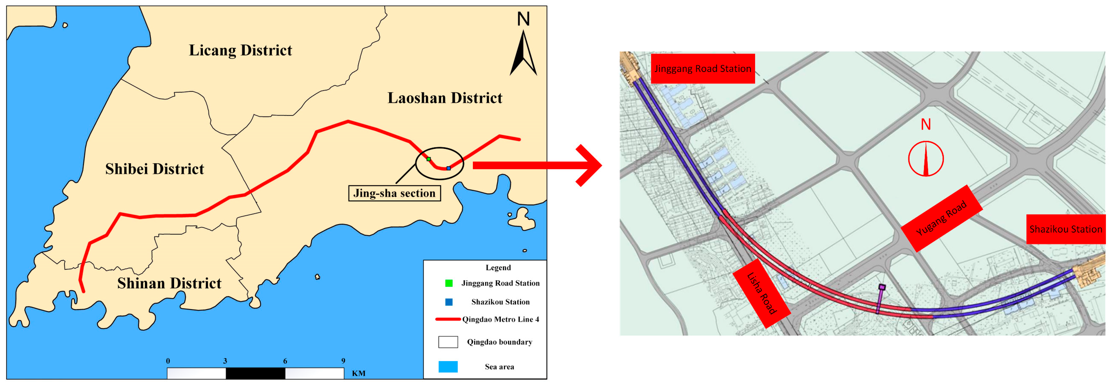
Qingdao Metro Line IV is the backbone line of the main urban area connecting Shinan District, Shibei District and Laoshan District. The Jing-sha Section is located between Jinggang Road Station and Shazikou Station in Laoshan District, Qingdao City, and its location is shown in Figure 1. After leaving Jinggang Road Station, the section tunnel is laid southward along the middle of Lisha Road, and then deviates from Lisha Road near the intersection of Yugang Road, heading east towards Shazikou Station. The tunnel consists of two parallel single-hole tunnels with a spacing of 13.8 m. The starting and ending mileage of the interval tunnel is (Z) YDK24+739.400-(Z) YDK25+879.000, with a total length of 1139.600 m.

2.2. Geological Conditions

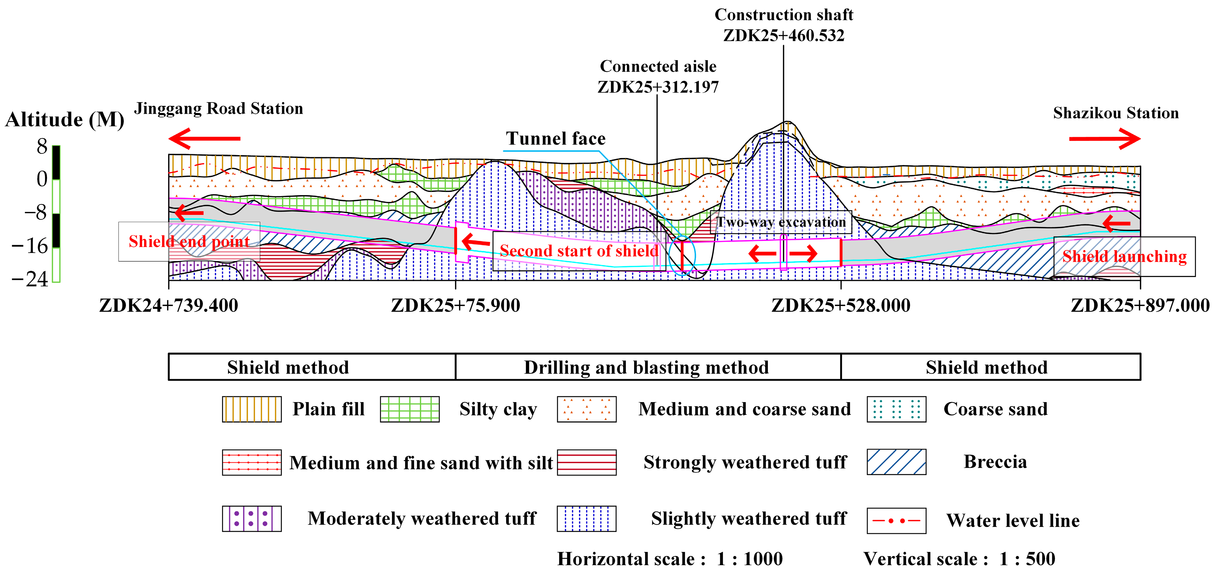
Figure 2 shows the geological profile of the Jing-sha section. The terrain in the section is relatively flat, and the tunnel passes through the corner of Dongjian Mountain at YDK25+355.000~YDK25+504.000. The buried depth of groundwater is 0.8–4.7 m. The stratum is mainly composed of plain fill, silty clay, medium-coarse sand, breccia (moderately weathered granite) and tuff with different weathering degrees. Table 1 shows the physical and mechanical parameters of the different section of ground. The bedrock in the interval is mainly slightly weathered tuff. The buried depth of the section tunnel is about 15.0–33.3 m, and the thickness of the overburden of the tunnel vault is about 9.5–27.8 m. Silty clay and sand are widely distributed, with the thickness of silty clay and sand being 0.8–4.8 m and 1.2–10.2 m, respectively. The tunnel is mainly located in moderately weathered granite and slightly weathered tuff strata, and partially located in strong and moderately weathered tuff strata.

2.3. Excavation and Support Methods

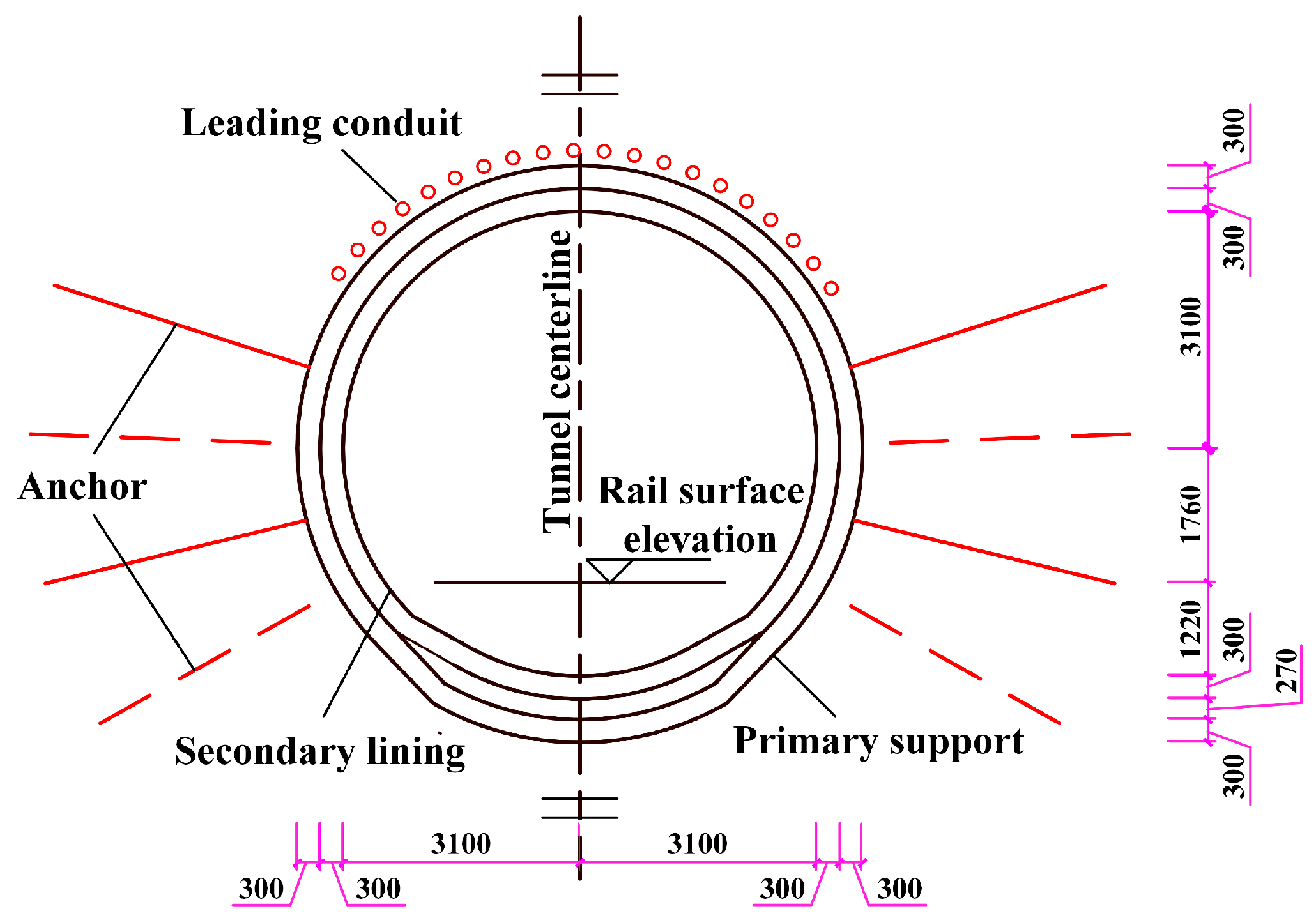
The construction methods of the tunnel are the shield method and the drilling and blasting method, and the areas used are shown in Table 2. The diameter of the shield tunnel is about 6.3 m. The section and support parameters of the drilling and blasting method tunnel are shown in Figure 3. The tunnel excavation area is about 7.5 m high and 7.4 m wide. The tunnel is excavated by the benching method. It is about 3.7 m high for the upper bench, 3.85 m high for the lower bench, and 3–5 m long for each bench. The initial support of the tunnel is grid steel frame and shotcrete. The grid steel frame spacing is 0.5 m. The shotcrete is C25 concrete with a thickness of about 300 mm. The permanent lining of the tunnel is 300 mm thick molded concrete consisting of C45 waterproof concrete and steel reinforcement. When the tunnel passes through an area with poor surrounding rock properties, Φ42 advanced small conduits (3.5 m in length and 15° inclination angle) are mounted into the rock in a 120° range around the extrados of the tunnel.
In addition, due to construction needs, there is a construction shaft and cross passage at YDK25+460.532.

2.4. Details of the Collapse

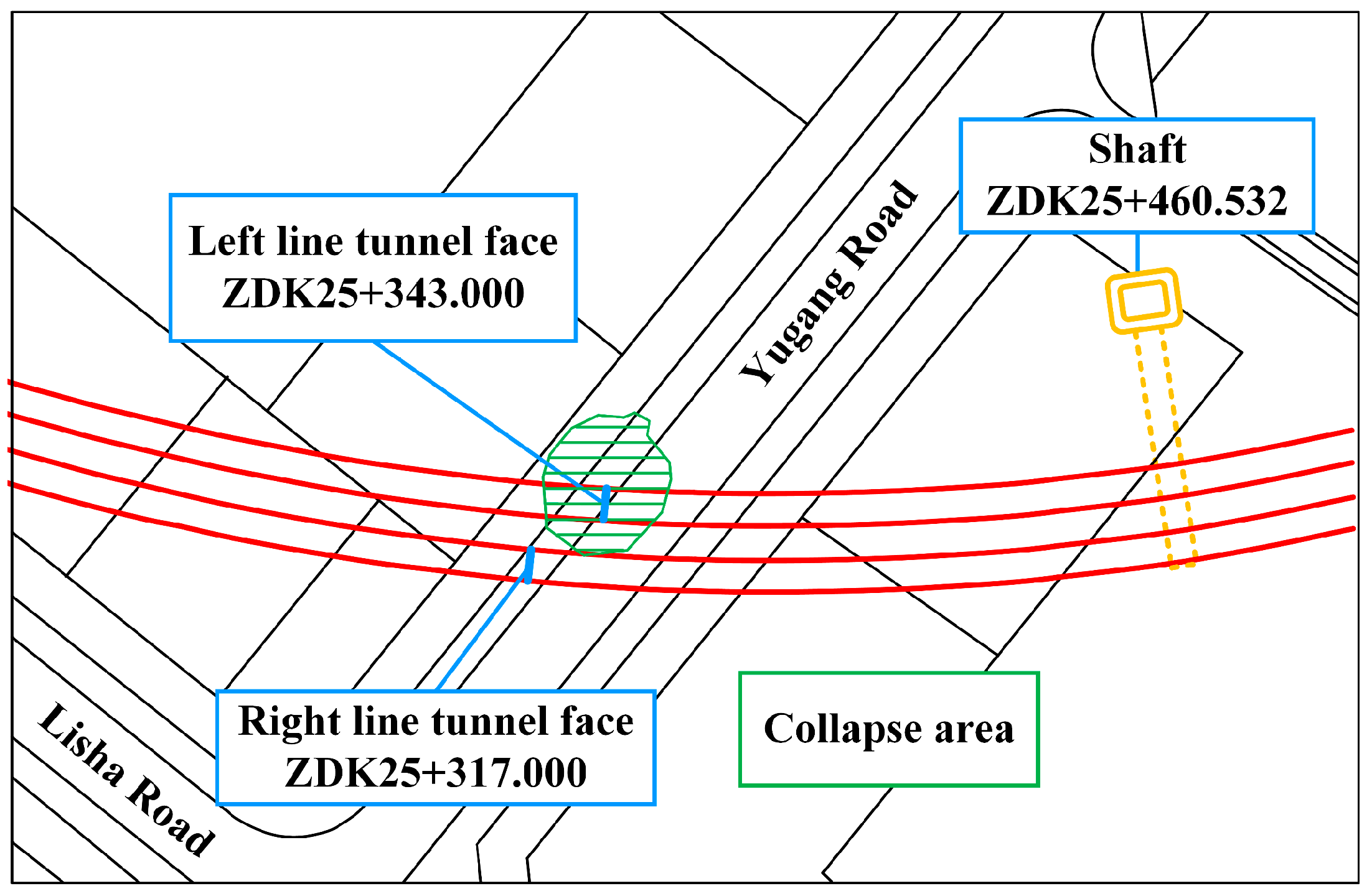
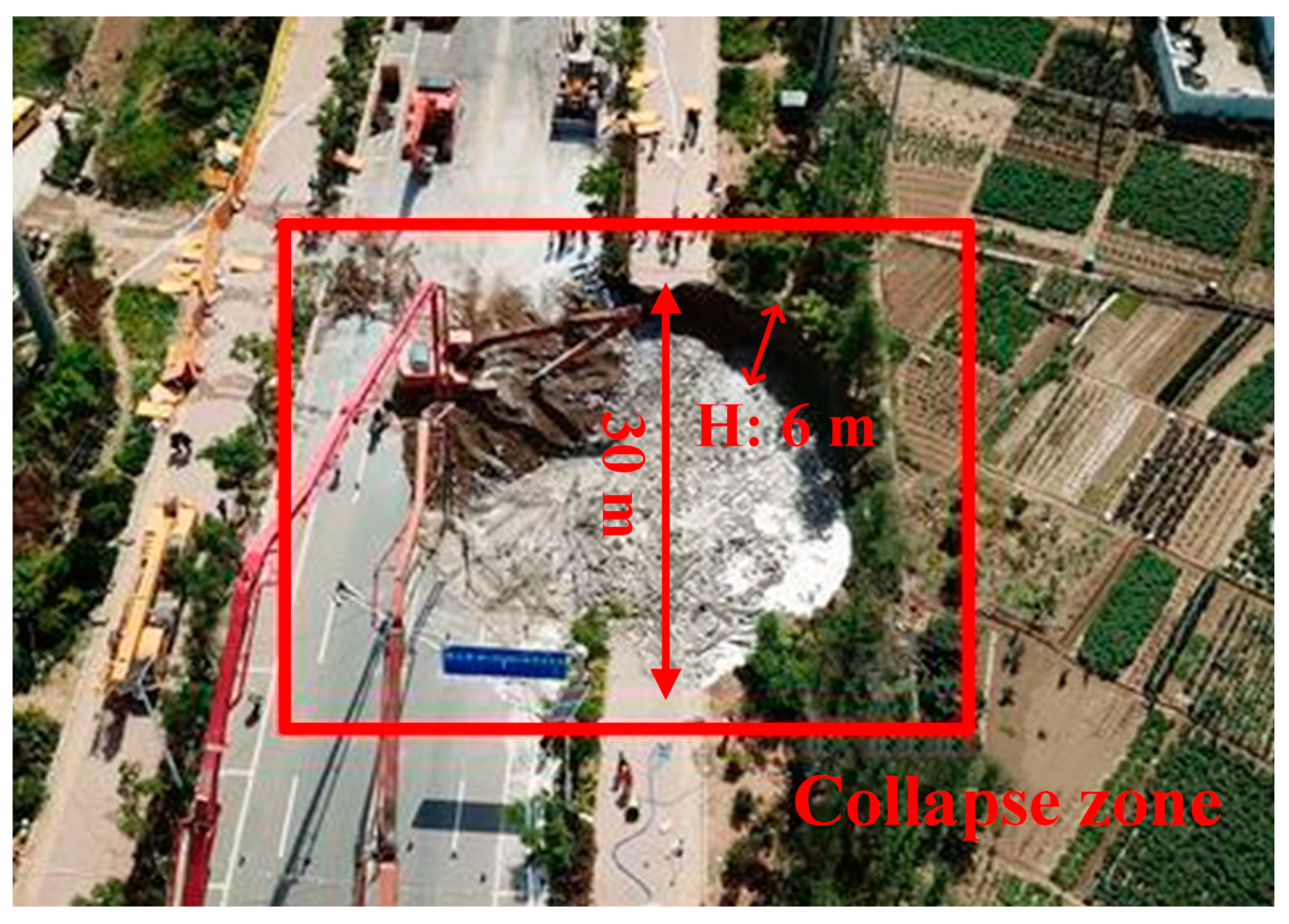
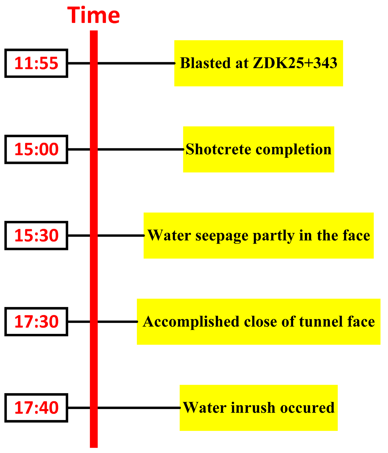
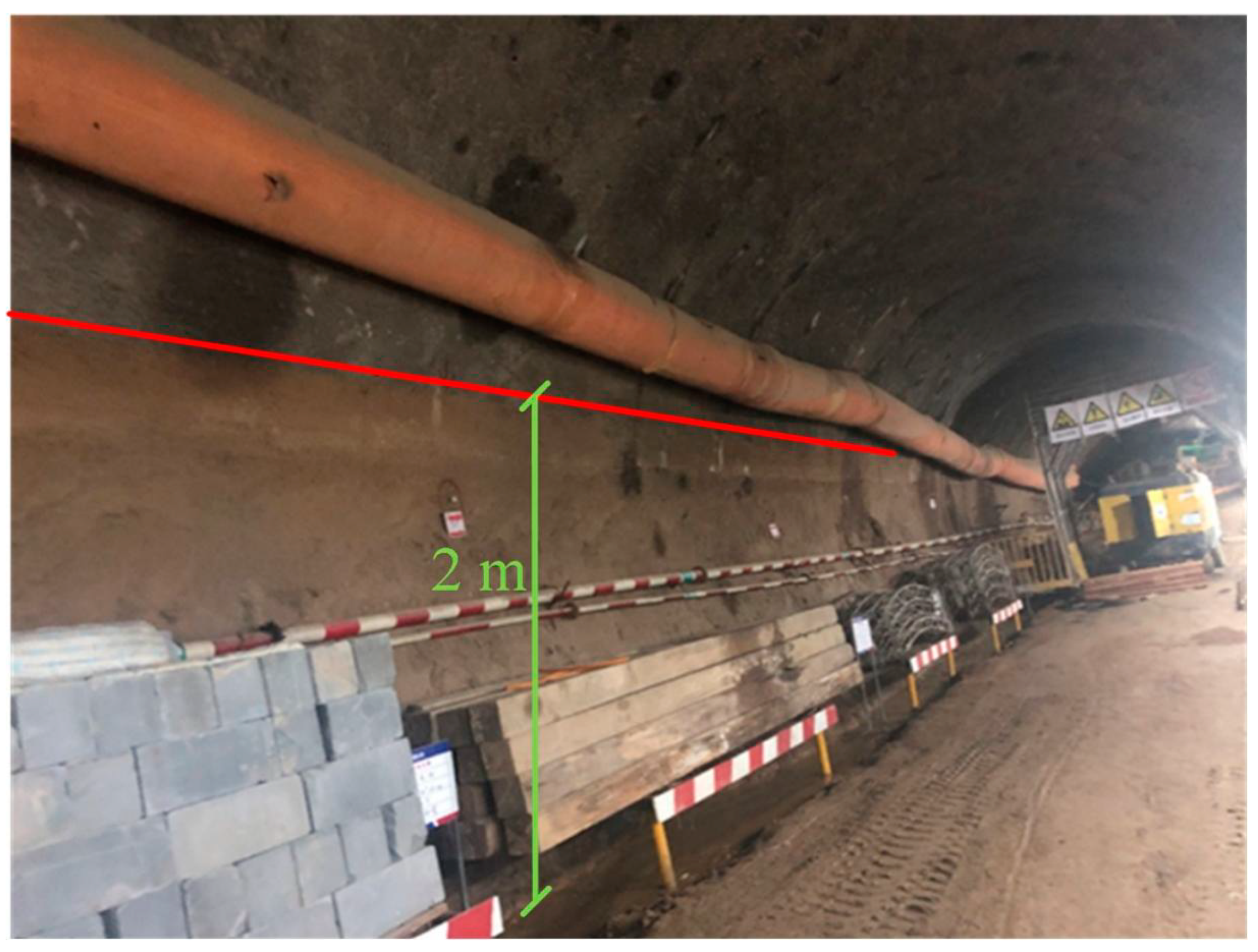
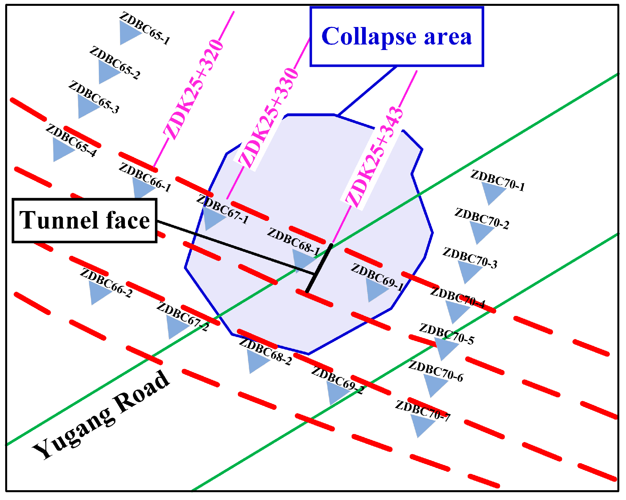
At about 17:40 p.m. on 27 May 2019, water and mud inrush occurred during the construction of the tunnel in the Jing-sha section, which caused ground collapse. The location of the collapse was ZDK25+343, which is located below Yugang Road, as shown in Figure 4. After the accident, a huge collapse pit with a length of 30 m, a width of 25 m and a height of 6 m was formed on the ground, as shown in Figure 5. It can be seen from the picture that the disaster caused damage to roads, surrounding farmland and underground pipelines. Figure 6 shows the process of collapse. At 15:30 on 27 May 2019, partial water seepage and block falling occurred on the face at ZDK25+343 on the left line, and the face was immediately treated by the conventional treatment method of shotcrete sealing with steel mesh. At about 17:30, closure construction of the face was completed, and there was no water seepage or block falling. At around 17:40, water and mud inrush appeared on the face. Generally speaking, the disaster developed from partial water seepage on the face of the tunnel, to water and mud inrush, and finally to ground collapse. However, there is no obvious precursor information before the water inrush occurred, which increases the difficulty of disaster identification. After the water and mud inrush occurred, the maximum velocity reached 20.885 m/s, and the mud reached the position of the cross passage (about 110 m from the tunnel face) within 11 s. According to estimates, the volume of sediment in this disaster was about 6924 m2. Figure 7 is a picture of the scene after the tunnel was cleaned up. Traces of muddy water can be clearly seen on the side wall of the tunnel. The height of the muddy water was about 2 m, which shows that the mud once occupied most of the entire tunnel area when the disaster occurred.

3. Analysis on the Causes of the Collapse

3.1. Factors Leading to the Collapse

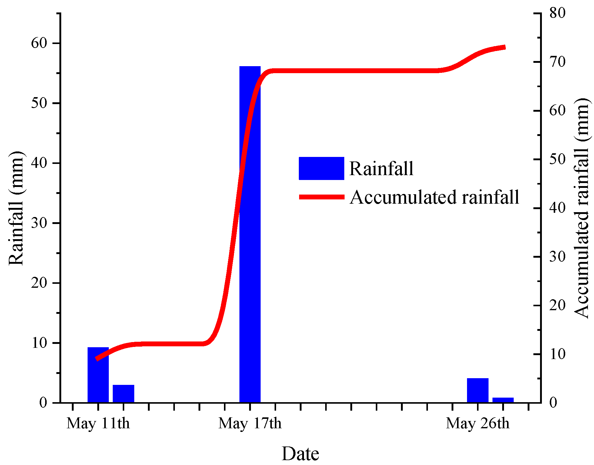
It is obvious from Figure 2 that the topography near the disaster location looks like a “funnel”, which made groundwater tend to converge at the bottom of the tunnel. The strata at the disaster location, from top to bottom, consists of a 6.4 m plain fill layer, a 0.8 m silt clay, a 7.1 m medium to coarse sand, a 4.9 m silt clay and tuff with different degrees of weathering. The tunnel is located in strongly weathered tuff and moderately weathered tuff. In the collapse zone, the tunnel passes through the bottom of a “funnel” with a buried depth of approximately 19.6 m, while the water level relative to the top of the tunnel is 19 m. As the tunnel was excavated, groundwater tended to flow into the tunnel at the bottom of the funnel. The strongly weathered tuff at the tunnel vault is extremely fragmented and fissures were developed. Tensile failure and crack expansion of the rock caused by the blasting vibration provided additional water channels. These factors caused the tunnel vault to bear a large water pressure. In this situation, the thickness of strongly weathered tuff at the tunnel vault in the collapsed area is only 0.7 m. According to the statistics, the cumulative rainfall in the Shazikou area from 11 May to 27 May was 73 mm, as shown in Figure 8. On 17 May, the rainfall was 56.1 mm. From 26–27 May, the rainfall continued for two days with an amount of 4.8 mm. The continuous rainfall provided ample recharge of groundwater, which worsened the situation. These two main factors are further analyzed in the next section.

3.2. Numerical Simulation for the Collapse

3.2.1. Establishment of Numerical Models

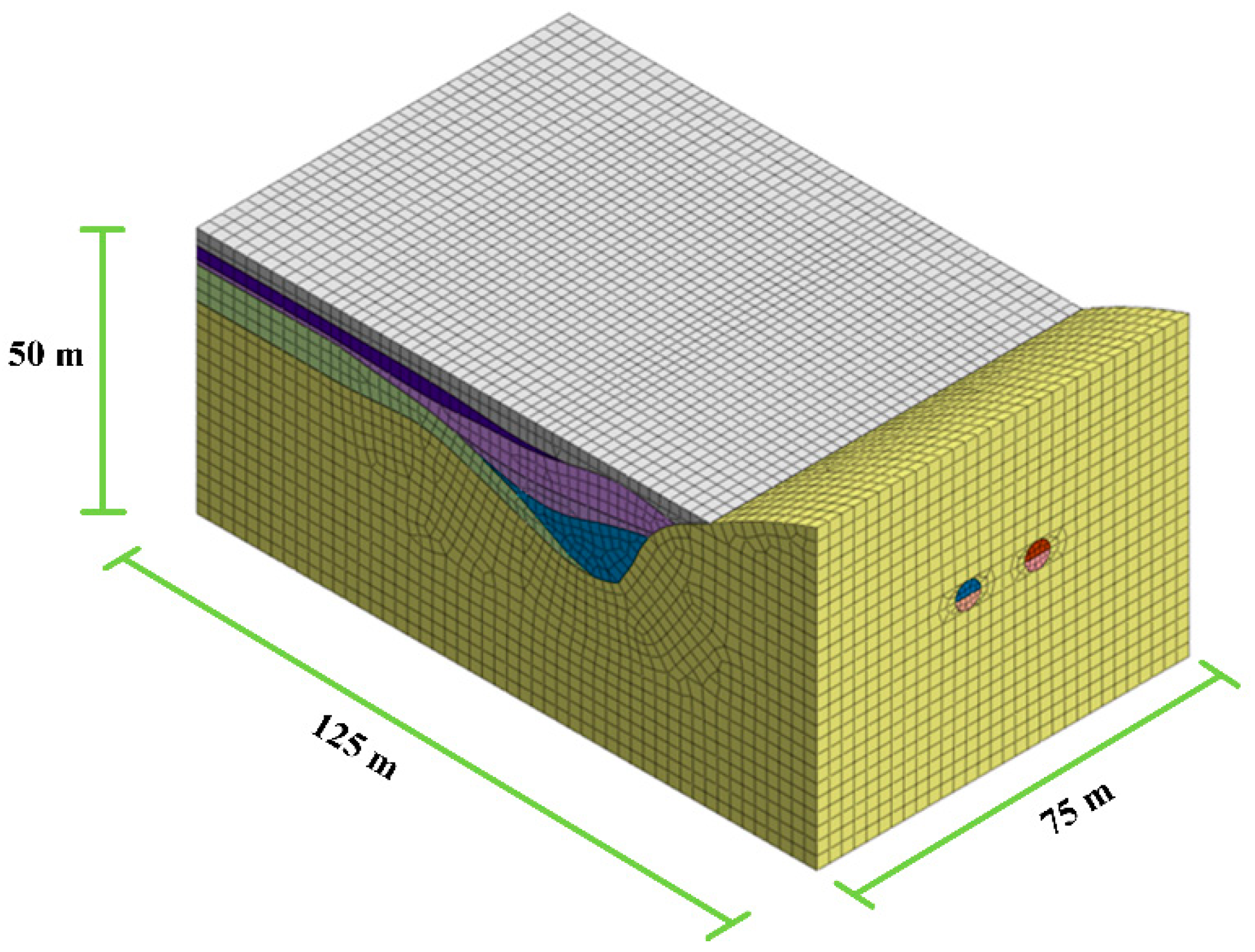
In this section, a numerical model is described to study the evolution of the disaster. Based on the practical geological of the tunnel from ZSK 25+270 to ZSK 25+395, a three-dimensional finite element numerical model was established by Midas GTX NX, as shown in Figure 9. The model size was 75 m × 125 m × 50 m, and the buried depth of tunnel was 19.6 m. In the numerical model, the yield condition, and the Mohr-Coulomb model, was used. The parameters of the model were taken according to Table 1. In accordance with the actual construction method of the project, the tunnel was excavated using the benching method. The left tunnel face was ahead of the right tunnel face with an interval of 10 m, with a single bench length of 5 m. The tunnel excavation range was from ZDK25+340 to ZDK25+395. After the excavation of each bench, C25 concrete with a thickness of 300 mm was used as the initial support, and the parameters are shown in Table 3. The groundwater level was set at −1 m. The left, right and bottom of the model are impermeable boundaries, and the surface of tunnel excavated was set as the permeable boundary.

3.2.2. Analysis of Settlement Results

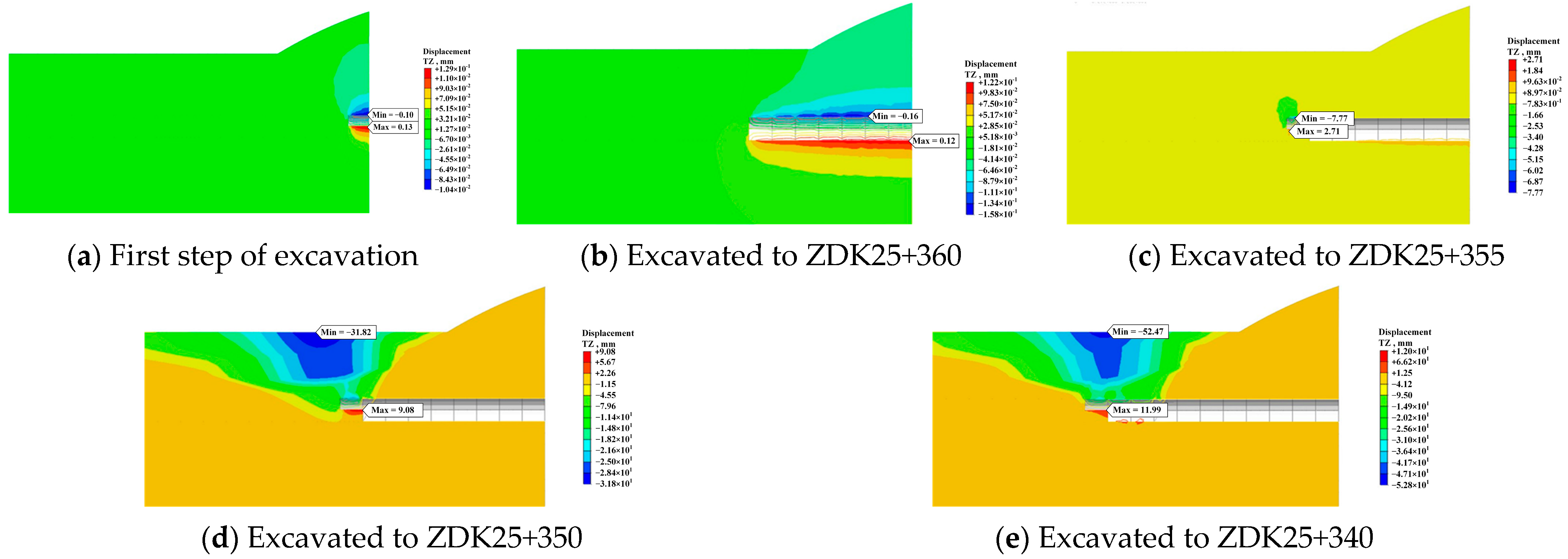
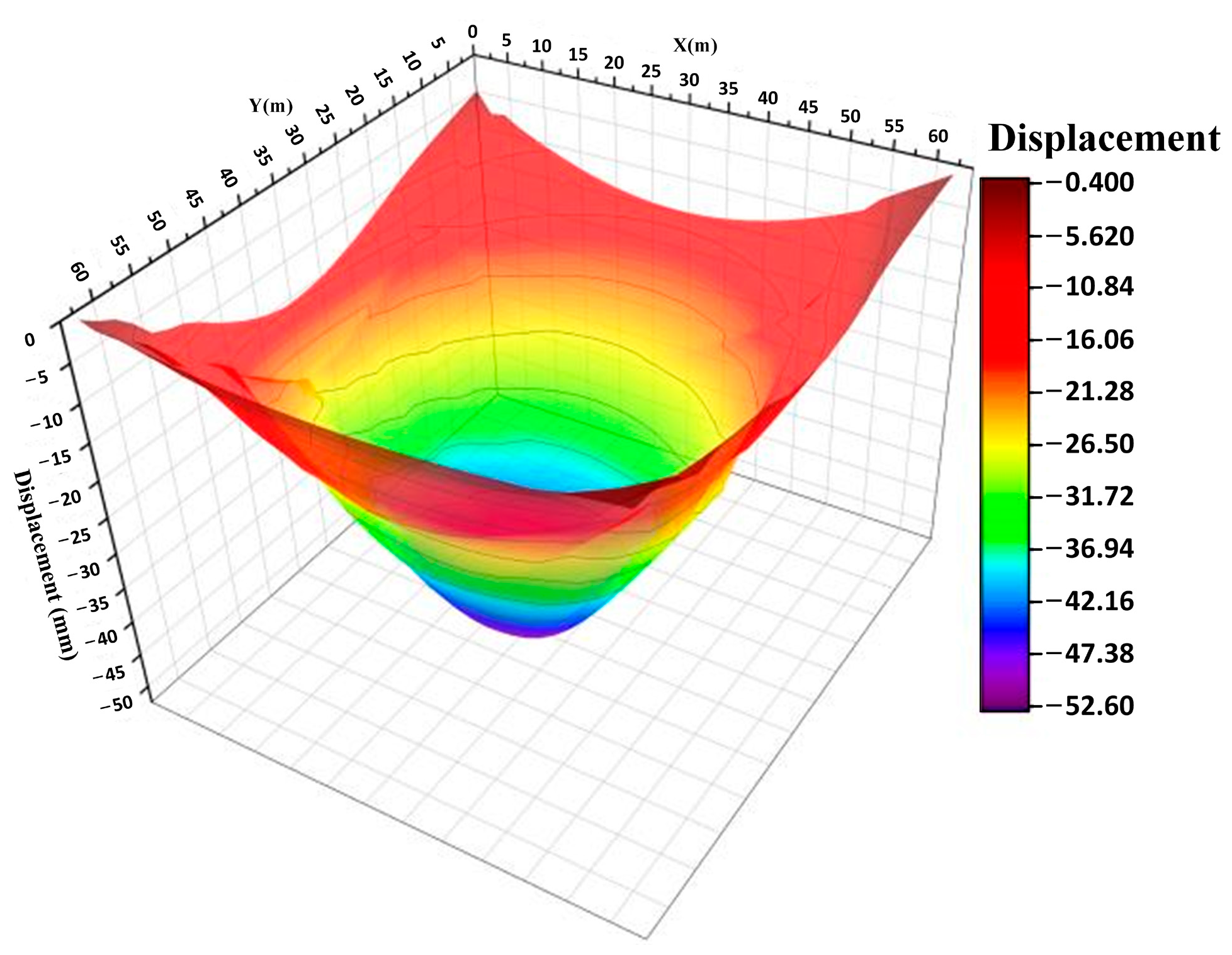
Figure 10 shows the settlement of the ground during excavation. The slightly weathered tuff is the dominant lithology from ZDK25+395 to ZDK25+360, and the grade of surrounding rock is III. Figure 10a,b shows the settlement of the tunnel during the excavation from ZDK25+395 to ZDK25+360. It can be seen from these pictures that the influence zone on the surrounding rock caused by excavation is minor, while the ground surface is basically unaffected. During this period, the excavation caused minor vault settlement, with a maximum settlement value of −0.16 mm. The strongly weathered tuff is the dominant lithology from ZDK25+360 to ZDK25+340, and the grade of surrounding rock is V. When excavated to ZDK25+355, the tunnel is located at the junction of slightly weathered tuff and strongly weathered tuff. During the excavation here, the tunnel vault in the strongly weathered tuff area settled significantly with a settlement value of −7.77 mm, as shown in Figure 10c. Meanwhile, the influence zone of the tunnel excavation started to extend towards the surface. When excavated to ZDK25+350, the surrounding rock of the tunnel consisted entirely of strongly weathered tuff. At this point, tunnel excavation caused significant settlement and had a large impact. Surface settlement was the largest factor, with a settlement value of −31.82 mm, as shown in Figure 10d, which exceeded the warning value of 30 mm required for tunnel monitoring. When excavated to ZDK25+340, the collapse zone, the surface settlement value increased to 52.47 mm, as shown in Figure 10e.
After excavation, near ZDK25+343, a cave-in with the diameter of 30 m appeared in the model, as shown in Figure 11. The actual collapse location is ZDK25+343, and the diameter of the collapse pit is about 30 m. The simulation results are consistent with the actual situation, indicating that the simulation is reliable.
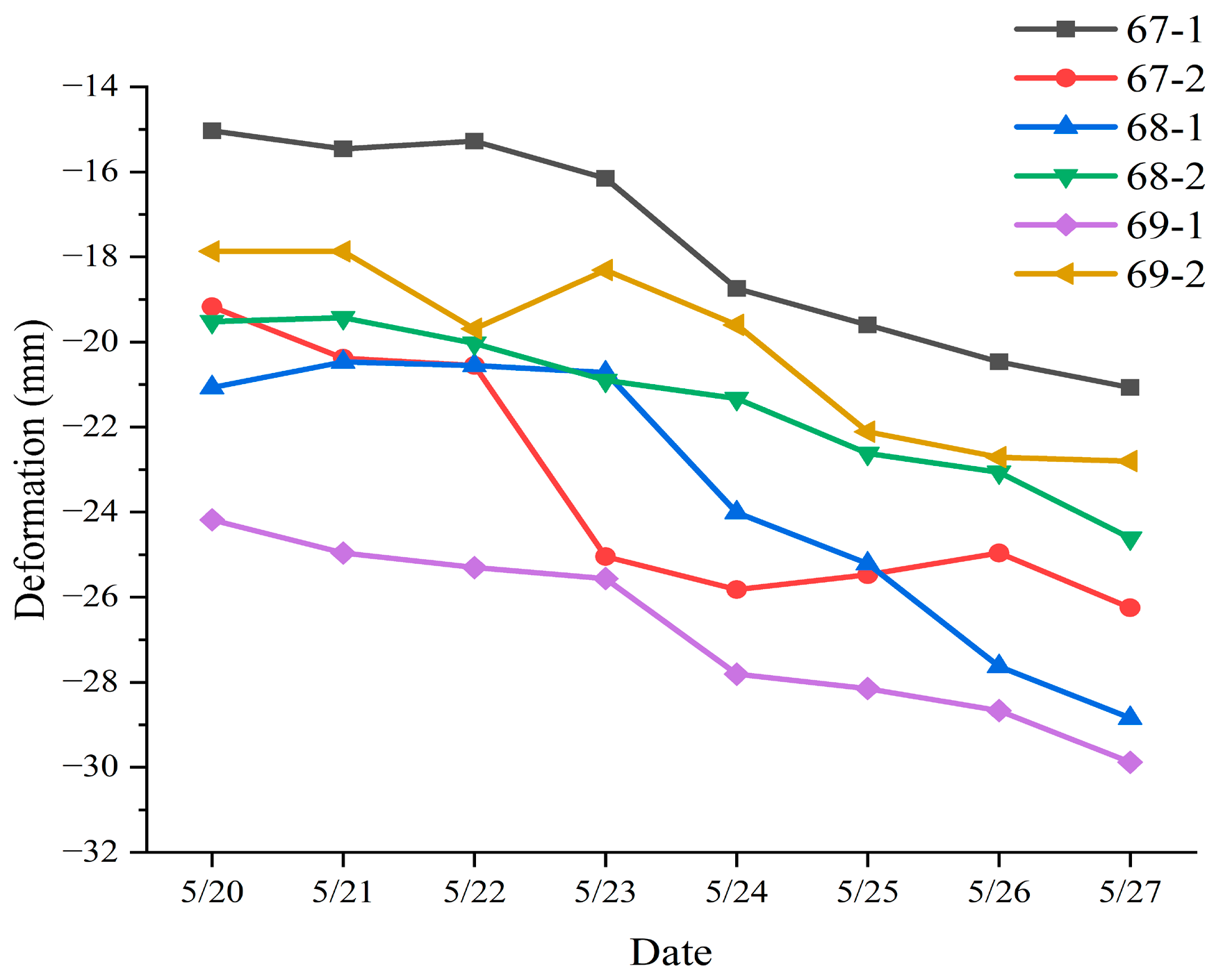
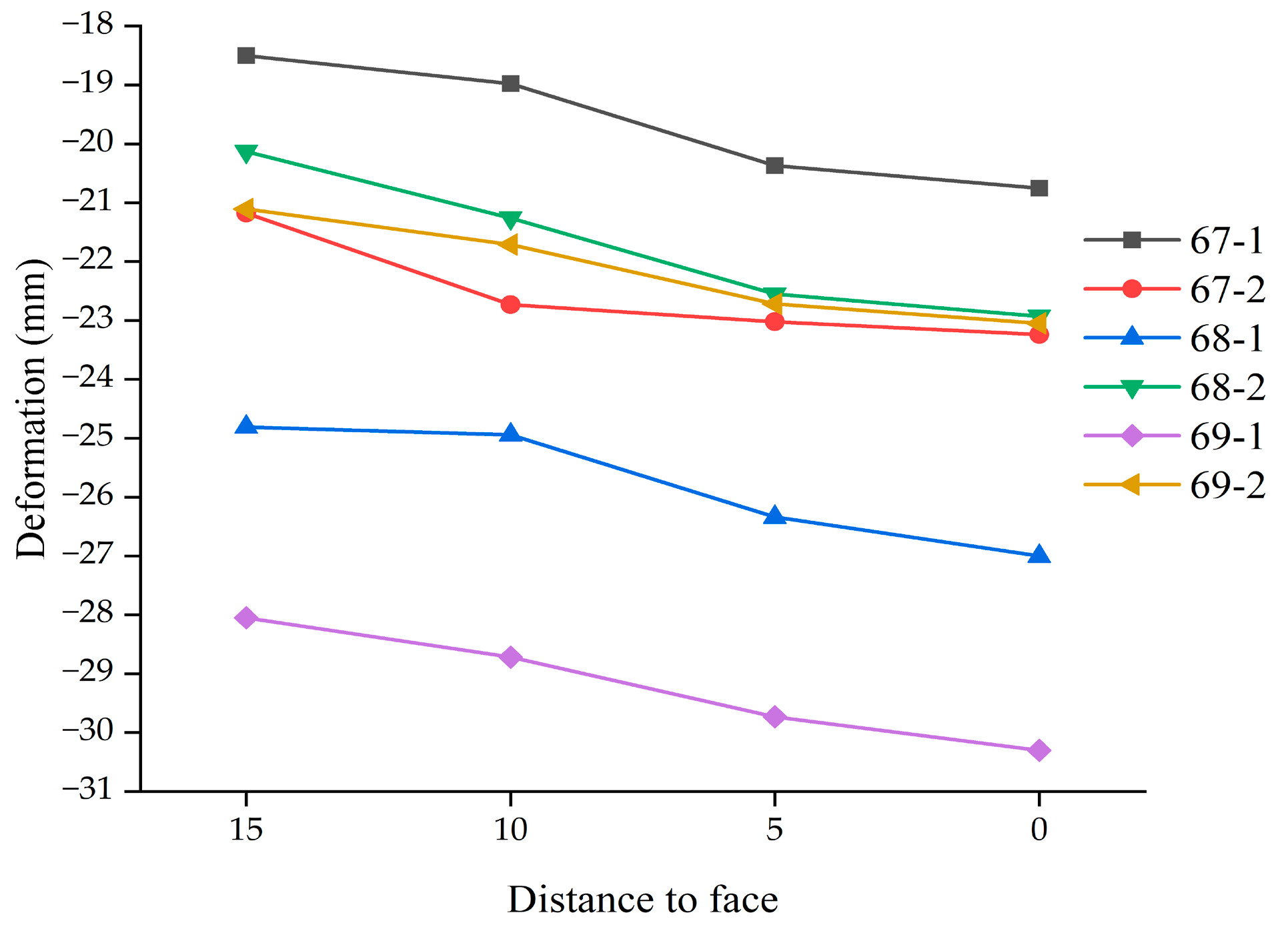
Before excavation, many monitoring points were set up at the surface. The distribution of monitoring points near the disaster area is shown in Figure 12. As can be seen from the figure, there are three groups of monitoring points located in the collapse area, namely ZDBC67, ZDBC68 and ZDBC69. The surface settlement of these three groups of monitoring points 7 days before the collapse is shown in Figure 13. From the figure, it can be seen that the collapsed area had a large settlement before the accident, and the maximum value of surface settlement was about 30 mm at ZDBC69-1. In particular, ZDBC67-2 showed a significant settlement abruptness with a deformation rate of 4.50 mm/d on 23 May. Corresponding to the locations of the three groups of monitoring points, the surface deformation data of the model during the excavation from ZDK25+355 to the collapse zone were extracted, and the results are shown in Figure 14. It can be seen from the figure that when excavated to ZSK25+355, i.e., at the intersection of strongly weathered tuff and slightly weathered tuff, the surface settlement was already large, and the maximum surface settlement was about 28 mm at ZDBC69-1. As the tunnel was excavated, ground deformation gradually increased. When excavated to the collapse zone, the maximum value of surface deformation was about 30 mm, which reached the warning value.
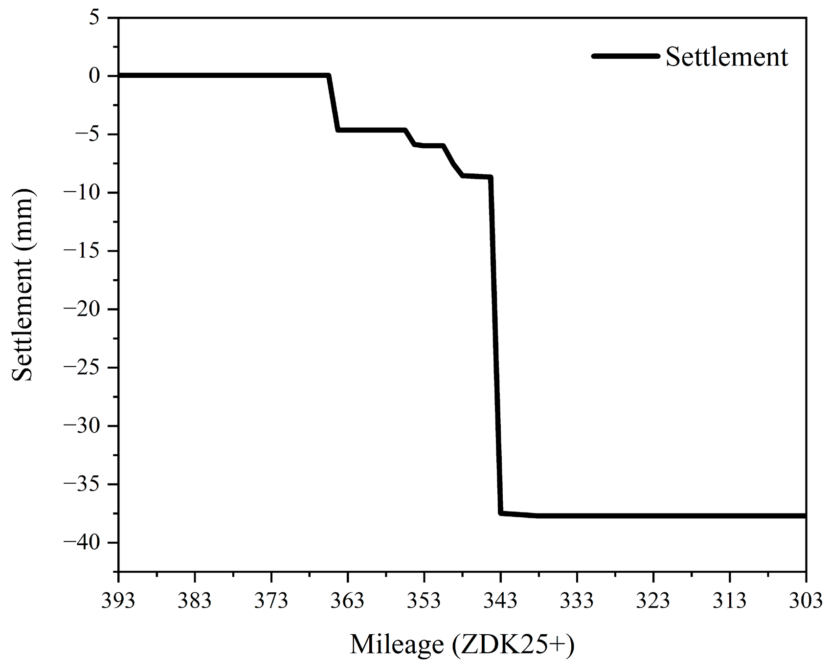
Figure 15 shows the deformation of the tunnel vault surrounding rock in the collapse zone during the simulation. Due to construction disturbance, the stratum in the collapse zone had settled before construction. When the excavation reached ZDK25+355, the tunnel vault settled obviously with a value of about 5 mm. When the excavation reached ZDK25+343, the settlement caused by the excavation increased abruptly, with a settlement value of 28.57 mm. The cumulative settlement during excavation reached 37.44 mm, which exceeded the warning value.
Comprehensive analysis of the monitoring data and simulation data showed that when the tunnel was excavated to the strongly weathered area, especially at the bottom of the funnel, the surface settlement as well as the vault settlement changed significantly, which indicated that adverse geological factors led to the disaster.

3.2.3. Analysis of Seepage Results

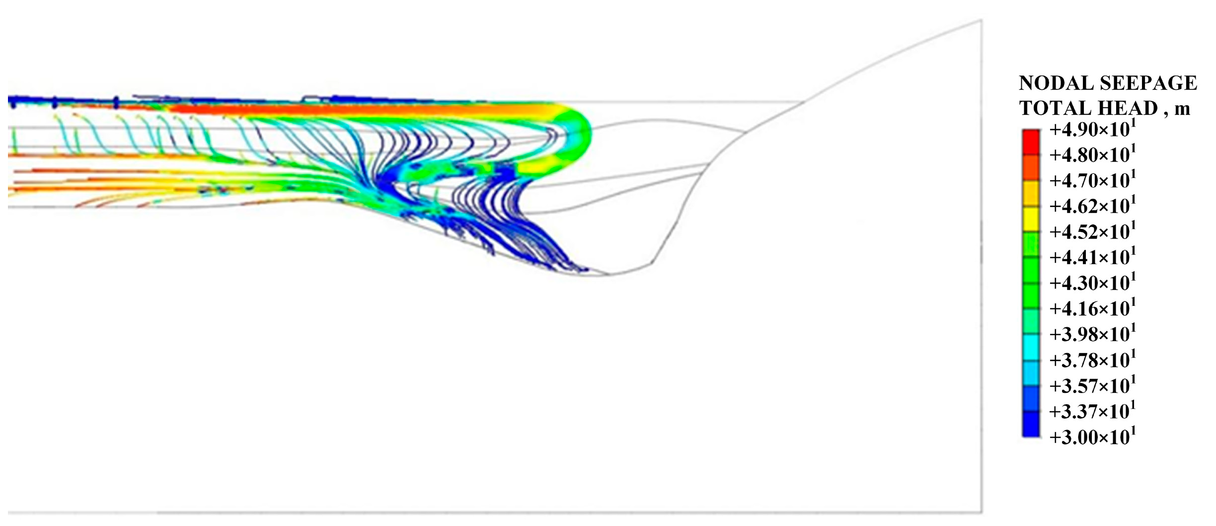
After tunnel excavation, the groundwater seeped towards the tunnel, as shown in Figure 16. As can be seen from the figure, when groundwater converged toward the bottom of the funnel, most of the groundwater bypassed the powdered clay layer due to the poor permeability of the powdered clay, which plays a certain role in water isolation. In this circumstance, the groundwater is more likely to seep downward from above the tunnel vault, resulting in a greater possibility of seepage failure of the surrounding rock.
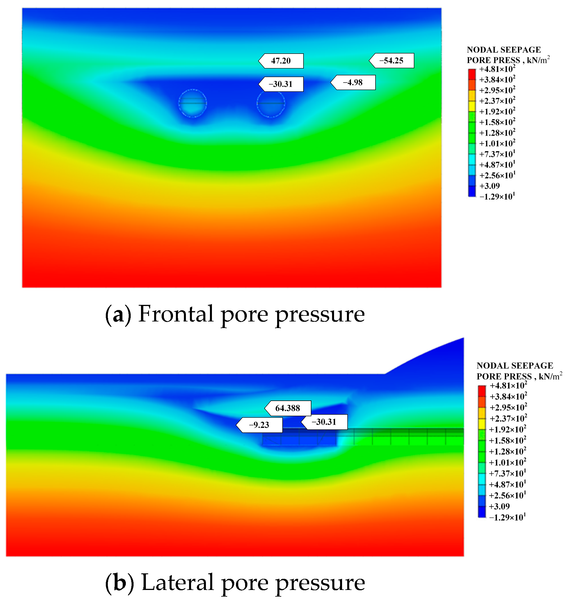
Figure 17 shows the pore water pressure of the ground at the time of the disaster. It can be seen from the figure that a negative pore water pressure zone was formed in a certain area around the tunnel when the disaster occurred. This indicates that the rate of groundwater loss in the region was greater than the rate of recharge. The existence of a negative pressure area increased the groundwater recharge, which indicates that water inrush would cause a larger range of groundwater recharge to the zone and result in an amount of water inflow far beyond the normal amount of water inflow in the area. This, water inrush caused a large amount of groundwater to gush into the tunnel and cause damage to the upper soil layer, causing the ground to collapse. At the site, the volume of water was about 4755.8 m3. According to the empirical formula of maximum water inflow in the Railway Code, as shown in Equation (1), the maximum water inflow in the area would be 4154.4 m3, which is less than the actual value.
Q = 0.0255 + 1.9224 K H
where K is the permeability coefficient of aquifers, and H is the distance from the resting water level to the center of the equivalent circle of the cave cross-section. Inadequate estimation of the water inflow in the tunnel was an important cause of the accident. The water inrush caused the groundwater level to drop significantly, causing the soil to consolidate and create ground subsidence.

4. Water Inrush Risk Assessment

4.1. Evaluation Index System for Water Inrush Risk

The main risk factors inducing water inrush disasters in tunnels include geological structure, landform, tunnel and surrounding rock conditions, and hydrological conditions [44]. Based on the geological characteristics of the Qingdao area, which is soft at the top and hard at the bottom, and combined with the actual engineering problems encountered in the excavation process of the Qingdao subway, the water inrush risk evaluation index system for subway tunnels in Qingdao area was established, as shown in Table 4.

4.2. A Novel Risk Assessment Method

An RBF neural network is a typical single hidden layer feedforward neural network, including an input layer, a hidden layer and an output layer. By mapping, the RBF neural network can transform low-dimensional, inseparable, original data into high-dimensional, linearly separable data, and obtain the implicit law of the original data to perform training fitting and evaluation prediction. At present, RBF neural networks are widely used in the fields of medicine, economy, and the environment. However, they are rarely used in tunnel water inrush risk assessment. The RBF neural network uses radial basis functions, a real-valued function that takes values that depend only on the distance from the centroid, as a mapping relationship to form the input layer data into the hidden layer space. Therefore, the choice of the center point of the RBF neural network is crucial to the performance of its network. Based on this, a PAM clustering algorithm was used to determine the center c of the hidden layer and the expansion constant σ_i to improve the accuracy of the RBF neural network. On the other hand, when using a neural network for learning, the more raw the data, the longer the calculation time and the larger the dimension. In actual computing, dimensionality reduction is often performed on the original data to reduce computing time. In the process of tunnel water inrush risk assessment, conventional dimensionality reduction methods invalidate the physical meaning and research significance of the data itself, which leads to the invalidation of the data. To ensure that the initial information is not corrupted, gray correlation analysis is introduced to reduce the dimensionality of the data.
Through the combination of gray relational analysis, a PAM clustering algorithm and RBF neural network, a tunnel water inrush risk assessment model was established. The evaluation process of the model is shown in Figure 18.

4.3. Application of Proposed Model

4.3.1. Training of Improved RBF Neural Network

According to the water inrush risk evaluation index system proposed in Section 4.1, the relevant indicators of the Kaisheng section of Qingdao Metro Line 1, the Wunan section of Qingdao Metro Line 2, and the Shimiao section of Qingdao Metro Line 2 were selected, as shown in the Table 5. These were used as the training data of the RBF neural network.
The training data were dimensionally reduced by grey correlation analysis. Taking the risk level as the parent sequence and the quantitative index value as the subsequence, we calculated the gray correlation coefficient between the subsequence and the indicators of the parent sequence and averaged them to obtain the correlation degree of each indicator, as shown in Table 6. Before calculation, all data were nondimensionalized using the initial value method to reduce analytical errors.
The indicators were sorted according to their correlation degree, and the first 12 index values with high correlation degree were selected as input values. The 12 sets of sample data were input as training data, and the actual water inrush risk levels (low risk, medium risk, high risk, and very high risk) were represented by numbers 1, 2, 3, and 4. In order to ensure the accuracy of the model, the optimal number of clusters was set to k = 4, and the maximum number of iterations when selecting the center for PAM clustering was 600 times. The improved RBF neural network was trained by the gradient descent method, the err-goal was 0.005, and the maximum number of iterations was set to 10,000. The training prediction results were completely consistent with the training samples, as shown in Table 7, indicating that the model met the training requirements.
Three parameters of different mileage in the static sediment interval were selected as the test sample data. According to the geological survey report and construction site data, the risk index parameters of water inrush in the static sand section were obtained through sorting, as shown in Table 8.
Three groups of test samples were evaluated for water inrush risk level, and the same data, which had been processed, was used to evaluate water inrush risk level through a traditional RBF neural network and BP neural network. The evaluation results are shown in Table 9.
It can be seen from Table 8 that the risk level of water inrush in the Jing-sha section of Qingdao Metro Line 4 predicted by the model was completely consistent with the actual risk level, indicating that the results of the model were reliable. In addition, compared with the traditional RBF neural network model and the BP neural network model, this model had higher prediction accuracy, better performance, smaller mean square error and did not easily to fall into the local optimal solution, indicating that the improved RBF neural network model could better fit the complex relationship between the risk level of water inrush and various factors.

4.3.2. Water Inrush Risk Assessment of Jing-Sha Section

Using the proposed model, the risk assessment of water inrush was carried out for the tunnel in the section from ZDK25+296.800 to ZDK25+402.130. The parameters of water inrush risk indicators in this interval are shown in Table 10.
Through calculation, the risk level of water inrush in this zone was IV, for special high risk. In fact, the water inrush accident introduced in 2.4 occurred in this interval, which is consistent with the predicted results. Through the risk level evaluation and identification of water inrush risk areas, staff could carry out safety protection procedures in advance, thereby reducing the occurrence of water inrush accidents during the construction process.

5. Conclusions

To investigate the disaster and clarify the causes of the disaster, a field survey and numerical simulation were conducted. A risk assessment method for tunnel water inrush was proposed to evaluate the risk. The main conclusions are as follows:
A funnel-shaped formation makes the groundwater converge towards the tunnel. The thickness of strongly weathered tuff at the tunnel vault in the collapsed area is only 0.7 m. At the same time, heavy rainfall increased the groundwater level and the water pressure. These geological conditions became the trigger factors of the accident.
This disaster was significant because of the poor surrounding rock and seepage pressure. When the tunnel was excavated from the slightly weathered area to the strongly weathered area, deformation increased abruptly. As the excavation proceeded, the excavation-affected area gradually expanded to the surface. The monitoring and simulation data showed that when the tunnel was excavated in the strongly weathered area, the surface settlement approached the warning value quickly. In addition, after the disaster, a negative pore water pressure zone formed around the tunnel, and increased the scope and scale of the accident as the water converged here.
A risk assessment index system for tunnel water inrush in Qingdao area is proposed. An improved RBF neural network was established by combining gray correlation analysis and a PAM clustering algorithm, and its reliability was verified. The water inrush risk level of the Jing-sha section was very high risk at level IV, which corresponds to the actual situation (water inrush). Making a proper risk assessment and taking the corresponding measures can effectively reduce engineering risks.
Author Contributions

Conceptualization, Y.Z. and B.G.; methodology, Y.Z. and B.G.; investigation, Y.Z., W.Z. and H.X.; formal analysis, H.X. and F.L.; validation, J.Z. and K.L.; data curation, Y.Z.; funding acquisition, Y.Z.; supervision, Y.Z. and B.G.; writing—original draft, Y.Z., W.Z. and H.X.; writing—review and editing, B.G. All authors have read and agreed to the published version of the manuscript.

Funding

This research was funded by the Demonstration Project of Benefiting People with Science and Technology of Qingdao, China (Grant No. 23-2-8-cspz-14-nsh), the Shandong Provincial Natural Science Foundation, China (Grant No. ZR2022QD102) and the National Natural Science Foundation of China, China (Grant No. 51674151).

Institutional Review Board Statement

Not applicable.

Informed Consent Statement

Not applicable.

Data Availability Statement

The datasets generated and/or analyzed during the current study are available from the corresponding author upon reasonable request.

Conflicts of Interest

The authors declare no conflict of interest.

References

  1. Xie, H.; Leung, C.; Wang, J.; Li, X. Advancing deep underground research through integration of engineering and science. Deep Undergr. Sci. Eng. 2022, 1, 1–2. [Google Scholar] [CrossRef]
  2. Hu, L.; Wang, J.; Karrech, A.; Li, X.; Zhao, P.; Liu, L. Exploring the frontiers of deep underground sciences and Engineer-ing—China Yunlong Lake Laboratory is striving to be the best. Deep Undergr. Sci. Eng. 2022, 1, 130–136. [Google Scholar] [CrossRef]
  3. Sousa, R.L.; Einstein, H.H. Lessons from accidents during tunnel construction. Tunn. Undergr. Space Technol. 2021, 113, 103916. [Google Scholar] [CrossRef]
  4. Liu, J.; Sun, Y.; Li, C.; Yuan, H.; Chen, W.; Liu, X.; Zhou, X. Field monitoring and numerical analysis of tunnel water inrush and the environmental changes. Tunn. Undergr. Space Technol. 2022, 122, 104360. [Google Scholar] [CrossRef]
  5. Li, S.; Gao, C.; Zhou, Z.; Li, L.; Wang, M.; Yuan, Y.; Wang, J. Analysis on the precursor information of water inrush in karst tunnels: A true triaxial model test study. Rock Mech. Rock Eng. 2019, 52, 373–384. [Google Scholar] [CrossRef]
  6. Yang, W.; Yang, X.; Fang, Z.; Shi, S.; Wang, H.; Bu, L.; Li, L.; Zhou, Z. Model test for water inrush caused by karst caves filled with confined water in tunnels. Arab. J. Geosci. 2019, 12, 749. [Google Scholar] [CrossRef]
  7. Zhou, Y.; Li, S.; Li, L.; Shi, S.; Zhang, Q.; Chen, D.; Song, S. 3D fluid-solid coupled model test on water-inrush in tunnel due to seepage from filled karst conduit. Chin J Rock Mech Eng 2015, 34, 1739–1749. [Google Scholar]
  8. Wang, Y.; Chen, F.; Li, X.; Yin, X.; Lei, Y. The variable-mass seepage law of broken porous rock: An experimental study. Geomat. Nat. Hazards Risk 2020, 11, 1991–2005. [Google Scholar] [CrossRef]
  9. Li, G.; Wang, K.; Gong, B.; Tao, Z.G.; Du, K. A multi-temporal series high-accuracy numerical manifold method for transient thermoelastic fracture problems. Int. J. Solids Struct. 2021, 230–231, 111151. [Google Scholar] [CrossRef]
  10. Wang, Y.; Gong, B.; Zhang, Y.; Yang, X.; Tang, C. Progressive fracture behavior and acoustic emission release of CJBs affected by joint distance ratio. Mathematics 2022, 10, 4149. [Google Scholar] [CrossRef]
  11. Fu, M.; Zhao, G.F. High-performance computing of 3D blasting wave propagation in underground rock cavern by using4D-LSM on TianHe-3 prototype E class supercomputer. Deep Undergr. Sci. Eng. 2022, 1, 87–100. [Google Scholar] [CrossRef]
  12. Chen, T.T.; Foulger, G.R.; Tang, C.A.; Mathias, S.A.; Gong, B. Numerical investigation on origin and evolution of polygonal cracks on rock surfaces. Eng. Geol. 2022, 311, 106913. [Google Scholar] [CrossRef]
  13. Li, S.; Liu, H.; Li, L.; Zhang, Q.; Wang, K.; Wang, K. Large scale three-dimensional seepage analysis model test and numerical simulation research on undersea tunnel. Appl. Ocean Res. 2016, 59, 510–520. [Google Scholar] [CrossRef]
  14. Jiang, Y.; Zhou, P.; Zhou, F.; Lin, J.; Li, J.; Lin, M.; Yongli, Q.; Wang, Z. Failure analysis and control measures for tunnel faces in water-rich sandy dolomite formations. Eng. Fail. Anal. 2022, 138, 106350. [Google Scholar] [CrossRef]
  15. Fan, H.; Li, L.; Chen, G.; Liu, H.; Gao, J.; Li, C.; Peng, X.; Zhou, S. Analysis method of the water inrush and collapse in jointed rock mass tunnels: A case study. Eng. Anal. Bound. Elem. 2023, 146, 838–850. [Google Scholar]
  16. Yan, F.; Qiu, W.; Sun, K.; Jiang, S.; Huang, H.; Hong, Y.; Hou, Z. Investigation of a large ground collapse, water inrush and mud outburst, and countermeasures during subway excavation in Qingdao: A case study. Tunn. Undergr. Space Technol. 2021, 117, 104127. [Google Scholar] [CrossRef]
  17. Huang, Z.; Zhao, K.; Li, X.; Zhong, W.; Wu, Y. Numerical characterization of groundwater flow and fracture-induced water inrush in tunnels. Tunn. Undergr. Space Technol. 2021, 116, 104119. [Google Scholar] [CrossRef]
  18. Kavvadas, M.J. Monitoring ground deformation in tunnelling: Current practice in transportation tunnels. Eng. Geol. 2005, 79, 93–113. [Google Scholar] [CrossRef]
  19. Masini, L.; Gaudio, D.; Rampello, S.; Romani, E. Observed Performance of a Deep Excavation in the Historical Center of Rome. J. Geotech. Geoenvironmental Eng. 2021, 147, 05020015. [Google Scholar] [CrossRef]
  20. Liu, F.; Zhang, Y.; Ma, T.; Tang, C.A. Observed performance of a deep excavation of Qingdao Metro Line 4 in China. Tunn. Undergr. Space Technol. 2022, 123, 104445. [Google Scholar] [CrossRef]
  21. Wang, Y.; Li, J.; Wang, Z.F.; Chang, H. Structural failures and geohazards caused by mountain tunnel construction in fault zone and its treatment measures: A case study in Shaanxi. Eng. Fail. Anal. 2022, 138, 106386. [Google Scholar] [CrossRef]
  22. Chen, L.; Wang, Z.; Wang, Y.; Bai, X.; Lai, J. Characteristics and failure analysis of a railway tunnel collapse influenced by cavity in phyllite strata. Eng. Fail. Anal. 2022, 142, 106794. [Google Scholar] [CrossRef]
  23. Liu, J.; Li, Z.; Zhang, X.; Weng, X. Analysis of Water and Mud Inrush in Tunnel Fault Fracture Zone—A Case Study of Yonglian Tunnel. Sustainability 2021, 13, 9585. [Google Scholar] [CrossRef]
  24. Liu, N.; Pei, J.; Cao, C.; Liu, X.; Huang, Y.; Mei, G. Geological investigation and treatment measures against water inrush hazard in karst tunnels: A case study in Guiyang, southwest China. Tunn. Undergr. Space Technol. 2022, 124, 104491. [Google Scholar] [CrossRef]
  25. Cheng, S.; Li, S.; Li, L.; Shi, S.; Zhou, Z.; Wang, J. Study on energy band characteristic of microseismic signals in water inrush channel. J. Geophys. Eng. 2018, 15, 1826–1834. [Google Scholar] [CrossRef] [Green Version]
  26. Gong, B.; Liang, Z.Z.; Liu, X.X. Nonlinear deformation and failure characteristics of horseshoe-shaped tunnel under varying principal stress direction. Arab. J. Geosci. 2022, 15, 475. [Google Scholar] [CrossRef]
  27. Wang, Y.; Gong, B.; Tang, C. Numerical investigation on anisotropy and shape effect of mechanical properties of columnar jointed basalts containing transverse joints. Rock Mech. Rock Eng. 2022, 55, 7191–7222. [Google Scholar] [CrossRef]
  28. Chen, G.; Liu, X.; Song, D. Research on in situ stress inversion of deep-buried tunnel based on pressure/tension axis mechanism and geological structure. Deep Undergr. Sci. Eng. 2023, 2, 1–13. [Google Scholar] [CrossRef]
  29. Feng, X.H.; Gong, B.; Cheng, X.F.; Zhang, H.H.; Tang, C.A. Anisotropy and microcrack-induced failure precursor of shales under dynamic splitting. Geomat. Nat. Hazards Risk 2022, 13, 2864–2889. [Google Scholar] [CrossRef]
  30. Guillermo Federico, S.L. Stochastic and Economic Evaluation of Adaptability in Tunneling Design and Construction. Ph.D. Dissertation, Massachusetts Institute of Technology, Cambridge, MA, USA, 1983. [Google Scholar]
  31. Nilsen, B.; Palmström, A.; Stille, H. Quality control of a sub-sea tunnel project in complex ground conditions. In Proceedings of the ITA World Tunnel Congress, Oslo, Norway, 31 May–3 June 1999; pp. 137–145. [Google Scholar]
  32. Kampmann, J.; Eskesen, S.D.; Summers, J.W. Risk assessment helps select the contractor for the Copenhagen Metro System. In Proceedings of the World Tunnel Congress 1998, São Paulo, Brazil, 25–30 April 1998; pp. 123–128. [Google Scholar]
  33. Wu, Q.; Liu, Y.; Liu, D.; Zhou, W. Prediction of floor water inrush: The application of GIS-based AHP vulnerable index method to Donghuantuo coal mine, China. Rock Mech. Rock Eng. 2011, 44, 591–600. [Google Scholar] [CrossRef]
  34. Chen, C.; Zhang, L.; Tiong, R.L.K. A novel learning cloud Bayesian network for risk measurement. Appl. Soft Comput. 2020, 87, 105947. [Google Scholar] [CrossRef]
  35. Sousa, R.L.; Einstein, H.H. Risk analysis during tunnel construction using Bayesian Networks: Porto Metro case study. Tunn. Undergr. Space Technol. 2012, 27, 86–100. [Google Scholar] [CrossRef]
  36. Zhou, Z.; Goh, Y.M.; Shi, Q.; Qi, H.; Liu, S. Data-driven determination of collapse accident patterns for the mitigation of safety risks at metro construction sites. Tunn. Undergr. Space Technol. 2022, 127, 104616. [Google Scholar] [CrossRef]
  37. Pan, Y.; Zhang, L. Mitigating tunnel-induced damages using deep neural networks. Autom. Constr. 2022, 138, 104219. [Google Scholar] [CrossRef]
  38. Wang, Z.; Chen, C. Fuzzy comprehensive Bayesian network-based safety risk assessment for metro construction projects. Tunn. Undergr. Space Technol. 2017, 70, 330–342. [Google Scholar] [CrossRef]
  39. Pan, Y.; Zhang, L.; Li, Z.; Ding, L. Improved fuzzy Bayesian network-based risk analysis with interval-valued fuzzy sets and D–S evidence theory. IEEE Trans. Fuzzy Syst. 2019, 28, 2063–2077. [Google Scholar] [CrossRef]
  40. Wang, X.; Li, S.; Xu, Z.; Lin, P.; Hu, J.; Wang, W. Analysis of factors influencing floor water inrush in coal mines: A nonlinear fuzzy interval assessment method. Mine Water Environ. 2019, 38, 81–92. [Google Scholar] [CrossRef]
  41. Kim, J.; Kim, C.; Kim, G.; Kim, I.; Abbas, Q.; Lee, J. Probabilistic tunnel collapse risk evaluation model using analytical hierarchy process (AHP) and Delphi survey technique. Tunn. Undergr. Space Technol. 2022, 120, 104262. [Google Scholar] [CrossRef]
  42. Aalianvari, A.; Katibeh, H.; Sharifzadeh, M. Application of fuzzy Delphi AHP method for the estimation and classification of Ghomrud tunnel from groundwater flow hazard. Arab. J. Geosci. 2012, 5, 275–284. [Google Scholar] [CrossRef]
  43. Wang, X.; Li, S.; Xu, Z.; Li, X.; Lin, P.; Lin, C. An interval risk assessment method and management of water inflow and inrush in course of karst tunnel excavation. Tunn. Undergr. Space Technol. 2019, 92, 103033. [Google Scholar] [CrossRef]
  44. Xue, Y.; Kong, F.; Li, S.; Qiu, D.; Su, M.; Li, Z.; Zhou, B. Water and mud inrush hazard in underground engineering: Genesis, evolution and prevention. Tunn. Undergr. Space Technol. 2021, 114, 103987. [Google Scholar] [CrossRef]
Figure 1. The location of Jing-sha section.
Applsci 13 03384 g001
Figure 2. Geological profile of Jing-sha section.
Applsci 13 03384 g002
Figure 3. Tunnel section and support parameters (unit: mm).
Applsci 13 03384 g003
Figure 4. Location of the disaster.
Applsci 13 03384 g004
Figure 5. Ground collapse.
Applsci 13 03384 g005
Figure 6. Evolution process of the disaster.
Applsci 13 03384 g006
Figure 7. Tunnel after cleaning.
Applsci 13 03384 g007
Figure 8. Rainfall in Shazikou area.
Applsci 13 03384 g008
Figure 9. Numerical model of tunnel.
Applsci 13 03384 g009
Figure 10. Settlement of the ground.
Applsci 13 03384 g010
Figure 11. Cave-in zone in model.
Applsci 13 03384 g011
Figure 12. Distribution of monitoring points.
Applsci 13 03384 g012
Figure 13. Surface settlement.
Applsci 13 03384 g013
Figure 14. Surface deformation at monitoring points.
Applsci 13 03384 g014
Figure 15. Settlement of the tunnel vault.
Applsci 13 03384 g015
Figure 16. Groundwater seepage.
Applsci 13 03384 g016
Figure 17. Negative pressure zone.
Applsci 13 03384 g017
Figure 18. Improved RBF neural network.
Applsci 13 03384 g018
Table 1. The parameters of different ground obtained from the geological report.
E/kPa μ eK/(m/Day)C/kPaφ
Plain fall80000.20.930015
Silty clay56710.330.7180.058.212
Sand60700.330.50.0513.912.5
Strongly weathered tuff20,0000.30.85.13.030
Moderately weathered tuff50,0000.250.81.728300045
Slightly weathered tuff5.00 × 1060.220.090.02611,50055
Table 2. Construction method of Jing-sha section.
Interval MileageConstruction MethodSegment Length
ZDK24+739.400~ZDK25+075.900shield method336.500 m
ZDK25+075.900~ZDK25+090.900The mining method is used as the initial support of the tunnel, and the secondary lining is poured. After the shield enters this section, it is reassembled and debugged, and the second launch is carried out in the mine method tunnel15.000 m
ZDK25+090.900~ZDK25+528.000The mine method is used as the initial support of the tunnel, and the second lining is poured after the shield tunnel passes through the437.100 m
ZDK25+528.000~ZDK25+879.000shield method351.000 m
YDK24+739.400~YDK25+063.200shield method323.800 m
YDK25+063.200~YDK25+078.200The mining method is used as the initial support of the tunnel, and the secondary lining is poured. After the shield enters this section, it is reassembled and debugged, and the second launch is carried out in the mine method tunnel15.000 m
YDK25+078.200~YDK25+568.000The mine method is used as the initial support of the tunnel, and the second lining is poured after the shield tunnel passes through489.800 m
YDK25+568.000~YDK25+879.000shield method311.000 m
Table 3. The empirical parameters of concrete.
E/kPa μ eK/(m/Day)C/kPaφ
Plain fall80000.20.930015
Silty clay56710.330.7180.058.212
Sand60700.330.50.0513.912.5
Strongly weathered tuff20,0000.30.85.13.030
Moderately weathered tuff50,0000.250.81.728300045
Slightly weathered tuff5.00 × 1060.220.090.02611,50055
C25 concrete2.20 × 1070.20.018.64 × 10−520,00060
Table 4. Risk assessment index system for tunnel water inrush in the Qingdao area.
Level 1 IndicatorsSecondary IndicatorsLevels of Danger
C4 (Low Risk)C3 (Medium Risk)C2 (High Risk)C1 (Very High Risk)
Tunnel and surrounding rock conditions I1Tunnel excavation width I11<8.5[8.5, 12)[12, 14)≥14
Tunnel depth I12<10[10, 30)[30, 50)≥50
Rock integrity I13wholebrokenBrokenextremely broken
Rock saturated uniaxial compressive strength I14>60(30, 60](15, 30]≤15
Degree of crack expansion I15underdevelopeddevelopmentmore developedvery developed
Basic quality grade of rock mass I16I, IIIIIIVV
Geological structure and surface factors I2Fault fracture zone width I21<50[50, 100)[100, 300)≥300
Catchment area/%I22<20[20, 40)[40, 60)≥60
Topography I23flatslopesteep terraces, valleysdenuded mounds, eroded plains
Composite ratio of soft and hard formations/%I24<25[25, 50)[50, 75)≥75
Hydrological conditions I3Water richness of groundwater I31no waterslightly waterywateryrich in water
Elevation difference of groundwater I32<10[10, 30)[30, 60)≥60
Permeability coefficient I33<0.01[0.01, 1)[1, 10)≥10
Average monthly rainfall I34<60[60, 80)[80, 100)≥100
Table 5. Training sample data.
Tunnel NameSampleGradeI11/mI12/mI13I14/MPaI15I16I21/%I22I23/%I31I32/mI33/md−1I34/mm
Kaisheng Section of Qingdao Metro Line 11I6.212.6whole44.23underdevelopedII41.35flat39.68slightly watery3.010.004359.5
2II6.212.8broken44.23more developedIV69flat84.4rich in water8.842.851259.5
3IV6.214extremely broken11.97developmentV77.21flat85.7rich in water124.492859.5
4IV6.213.95extremely broken10.8very developedVI75slope91rich in water10.4725.9259.5
Wunan section of Qingdao Metro Line 25II5.211.6broken137.3more developedIV11slope34.48slightly watery1.280.001357.9
6IV5.211.5extremely broken28.2very developedV28.43slope69.56watery3.275.18457.9
7II5.211broken28.2very developedV0.1flat21.8no water0.10.004257.9
8II5.210.4broken137.3more developedV31.25flat53.84slightly watery3.255.18457.9
Shimiao section of Qingdao Metro Line 29IV6.413.6broken15.6developmentVI77.43slope94.12rich in water9.731557.9
10III6.416broken26more developedV74.5flat93.75rich in water11.920.157.9
11I6.49.8whole57.3underdevelopedIV1.63denudation mound32.65slightly watery0.160.0157.9
12IV6.415.6extremely broken6.5very developedVI84.1flat91.76rich in water13.120.557.9
Table 6. Index correlation.
Quantitative Index ValueI11I12I13I14I15I16I21I22I23I31I32I33I34
Correlation0.8480.8620.9250.6750.9230.8780.8310.8250.9000.8920.8170.7180.832
Table 7. Comparison table of prediction results and training samples.
SampleRisk Level
Test-out124424224314
Sam-outIIIIVIVIIIVIIIIIVIIIIIV
Table 8. Risk index data of water inrush in each tunnel section of Jingsha section of Qingdao Metro Line 4.
SampleRisk LevelI11/mI12/mI13I14/MPaI15I16I21/%I22I23/%I31I32/mI33/md−1I34/mm
1I7.416.2whole93.22underdevelopedII21.6flat16.2watery1.40.0026118.6
2III7.417.74broken45.3developmentIV77.2flat87.4rich in water15.940.5184118.6
3IV7.416.6broken45.3developmentVI95.6flat98rich in water15.880.5184118.6
Note: sample 1: ZDK2+111.120~ZDK25+137.800; sample 2: ZDK25+137.800~ZDK25+296.800; sample 3: ZDK25+528.000~ZDK25+879.000.
Table 9. Gray relational PAM improved RBF neural network tunnel water inrush risk assessment results.
SampleRisk LevelModel Prediction
Gray Relational PAM Improves RBFRBFBP
1IIII
2IIIIIIIVIII
3IVIVIVIII
mean square error 0.04610.25000.7787
Table 10. Parameters of water inrush risk indicators in the Jing-sha interval ZDK25+296.800~ZDK25+402.130.
I11/mI12/mI13I14/MPaI15I16I21/%I22I23/%I31I32/mI33/md−1I34/mm
7.416.2whole93.22underdevelopedII21.6flat16.2slightly watery1.40.0026118.6
7.417.74broken45.3developmentIV77.2flat87.4rich in water15.940.5184118.6
7.416.6broken45.3developmentVI95.6flat98rich in water15.880.5184118.6
Disclaimer/Publisher’s Note: The statements, opinions and data contained in all publications are solely those of the individual author(s) and contributor(s) and not of MDPI and/or the editor(s). MDPI and/or the editor(s) disclaim responsibility for any injury to people or property resulting from any ideas, methods, instructions or products referred to in the content.