Article

Design of a Quick-Pressing and Self-Locking Temporary Fastener for Easy Automatic Installation and Removal

1
School of Intelligent Engineering, Shaoguan University, Shaoguan 512023, China
2
School of Mechanical Engineering, Dongguan University of Technology, Dongguan 523808, China
3
College of Mechanical Engineering, Zhejiang University, Hangzhou 310027, China
*
Author to whom correspondence should be addressed.
Appl. Sci. 2023, 13(5), 3004; https://doi.org/10.3390/app13053004
Submission received: 13 February 2023 / Revised: 22 February 2023 / Accepted: 22 February 2023 / Published: 26 February 2023
(This article belongs to the Special Issue Advanced Manufacturing and Precision Machining)

Abstract

:
In the traditional pre-joining technology of aircraft panels, bolts are generally employed for pre-joining. Due to the length and width of panels, bilateral manual operations are required to operate bolts. In this case, there are problems such as low work efficiency, unstable quality, cumbersome operation, and inconvenient installation-removal. This paper takes a temporary fastener with one-side installation-removal as a research object and conducts in-depth research on three levels of quick-pressing: unloading, stable self-locking, and easy automatic installation. Firstly, by coordinating the ratchet and the spring, the restoring force of the spring is used to make the cylindrical top-rod rotary and realize the telescopic function to achieve quick loading and unloading of fasteners; subsequently, through the cooperation between the buckle and the spring, loading and unloading self-locking is attained; afterwards, through the threaded joining and the same cylinder design between the external profile components, the convenience of fasteners for automatic transportation is realized. When assembling two thin-walled parts of the aircraft, only continuous one-side pressing of fasteners is needed to carry out the tightening and unloading work, namely, one-pressing installation and one-pressing removal, which could solve the problems caused by the bilateral operation of traditional bolts and part tolerances. After the application of the fasteners into the pre-joining process of aircraft panels, the experiment results have shown that this temporary fastener provided a good clamping effect, could be quickly and efficiently installed and removed by continuous one-pressing, and avoided the problems of complexity and high cost for pre-joining processes.

1. Introduction

In traditional aircraft manufacturing processes, numerous fasteners are used with parts in connection, and they play an important role in position and support. Traditional aircraft panel assembly often uses bolts for pre-joining, but the positioning accuracy and efficiency of bolts are not ideal. The clamping force cannot be accurately controlled by the intuitive judgment of workers, and the consistency of the clamping force cannot be guaranteed. At the same time, bilateral operations are required for bolts, which results in a cumbersome process and low efficiency. It is difficult to realize automated assembly for bolts, which directly affects the quality and efficiency of subsequent aircraft riveting assembly and has become a technological bottleneck in aircraft manufacturing processes.
Since the 1990s, scholars at home and abroad have conducted a number of studies on fasteners for thin-walled parts. Threaded connections are the most commonly used traditional technology [1,2]. Gong Hao et al. [3] summarized the reasons for and mechanisms of non-rotating and rotating loosening on threaded connections. Shan, ZW et al. [4] conducted a sample test on a direct fastening connection and proposed a modified expression for the yield strength of the connection. In order to solve the connection problem of steel pipe structures, some scholars [5,6] have developed special bolts, such as HSBB bolts, BOM bolts, and Ultra-Twist bolts, produced by the American company Huck International.
Furthermore, in response to the problem of excessive connections in traditional panel assembly, Wei Tang et al. established a pre-joining optimization model and verified it through experiments, which could effectively reduce the number of pre-joining points [7,8,9]. However, they did not involve the design and optimization of pre-joining fasteners. In addition, C. Kim et al. [10,11,12,13] have conducted studies on the application of blind rivet nuts. Lele Sun [14] presented a novel form of T-shaped single-sided bolt connections for steel beams and hollow square steel tubes. Other researchers have proposed alternative connectors, such as the rotating slotted bolt connection [15], the high-strength single-sided bolt joint [16], and other fasteners for single-sided connections [17,18,19]. These above-mentioned fasteners can also be fitted on one side, but their structure is too complex to install on panels, or the operation must be tightened many times, making the operation laborious, inefficient, and difficult to process, so they are not ideal for connecting aircraft parts. To solve the traditional pre-joining process problems of large tightening torque and inconvenient bilateral tightening, W. Tang et al. [20] proposed a new temporary fastener that is labor-saving and reversible, which was performed by experiment. However, this fastener needs to be rotated back and forth during installation, and this installation process is not as simple as linear motion.
In order to overcome the shortcomings and deficiencies of traditional technology, this paper designs a quick-pressing temporary fastener with self-locking capabilities that is convenient for automatic installation and removal. When fastening or removing, it needs only one-side continuous pressing operation to carry out the above-mentioned work, that is, one-button installation and removal, which is conducive to the combination of the fasteners and automation, and is more compatible with automatic equipment loading and unloading to improve efficiency. Finally, this paper builds a model with 3D software, theoretically analyzes the critical state and final state of temporary fastener pressing, and designs an experiment to verify its actual effect.

2. Function and Principal Innovation

2.1. Function and Structure Innovation

In order to solve various installation problems caused by traditional bolt connections, some innovations for fasteners in function and structure have been proposed, as shown in Table 1.
The quick-pressing and self-locking temporary fastener is composed of a button, a transmission component, a shell, and a clamping component. The button is connected to one end of the transmission component; the other end of the transmission component has a sliding connection to the clamping component; and the transmission component is sleeved in the shell. The button and the clamping assembly pass through the shell; a spring is arranged between the shell and the button, and the end of the clamping assembly protruding out of the shell is provided with a barb. The overall structure is shown in Figure 1.

2.2. Working Principle of Fasteners and Steps of Loading and Unloading

2.2.1. Working Principle

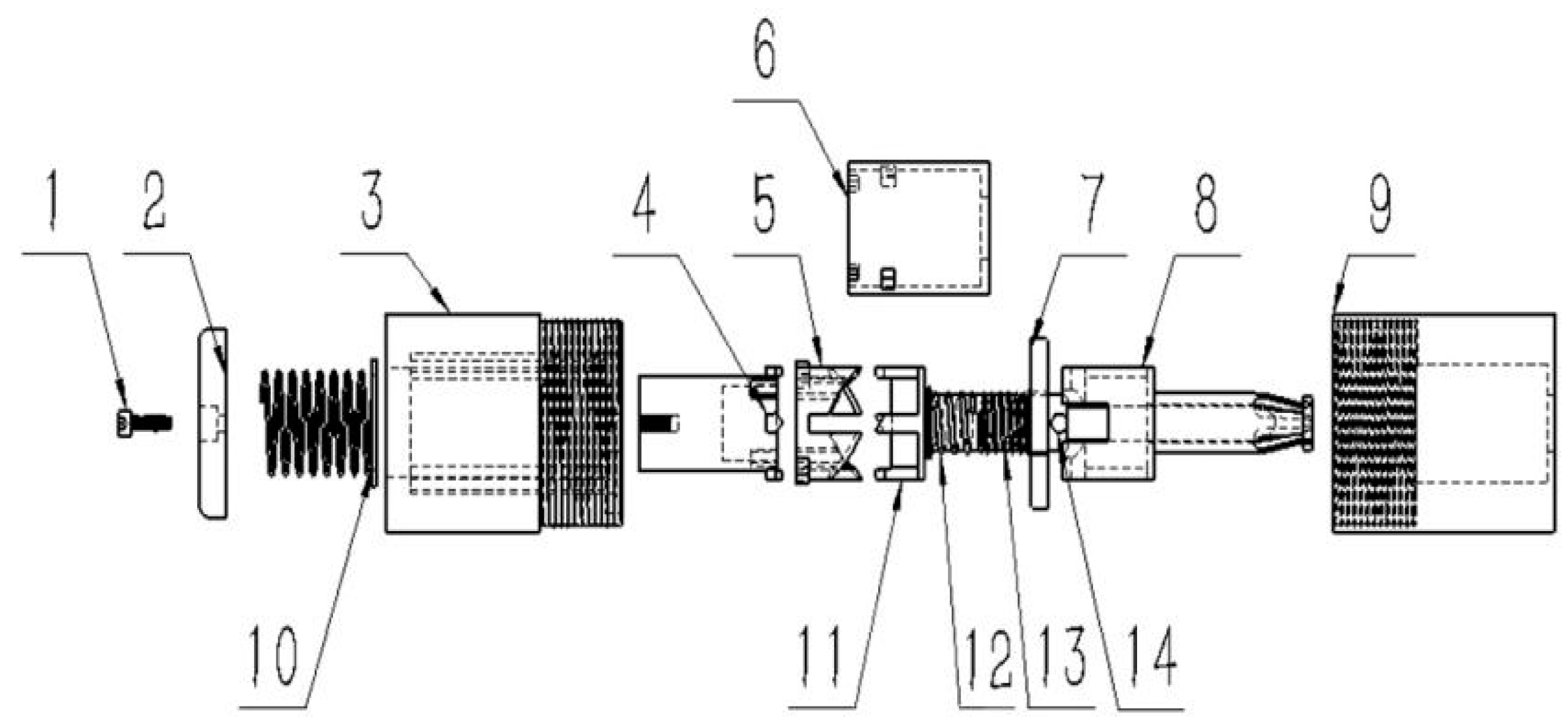
First, the four-petal structure of the clamping jaw is used as the main part of the joining plates. This four-petal structure has the characteristics of elastic contraction and expansion. When working, the petal structure expands due to the external forces applied to fasten the connecting panels. When disassembling, the expanded shape of the petals contracts to loosen the connector. This design solves the problem of precise clamping to connection. Meanwhile, a ratchet mechanism is designed to carry out the unilateral operation of work and disassembly. Each time the round button is pressed, the cylindrical push rod rotates 90°, and this causes the mandrel to rotate to realize the fastening and loosening of the four-part clamping jaws, so as to achieve the work and disassembly without damaging the fastener itself. The design explosion diagram is shown in Figure 2.
The head shell (9) and clamping jaw (8) have a square groove at one end; the clamping jaw (8) slides into the inner square; and the other end is a four-petal claw structure with a tapered barb shape. Simultaneously, the round button (2) and the cylindrical push rod (4) are screwed together; the cylindrical push rod (4) and cylindrical top rod (11) are installed in the ratchet (5) groove; and the spring of the ejector rod (12) and the supporting spring (13) are sleeved on the cylindrical top rod (11). At the same time, two springs are installed inside and outside of the inner sleeve (6); the baffle (7) is installed in the tail shell (3); and the head shell (9) and tail shell (3) are threaded together.

2.2.2. Fast Installation and Removing Method of Fasteners

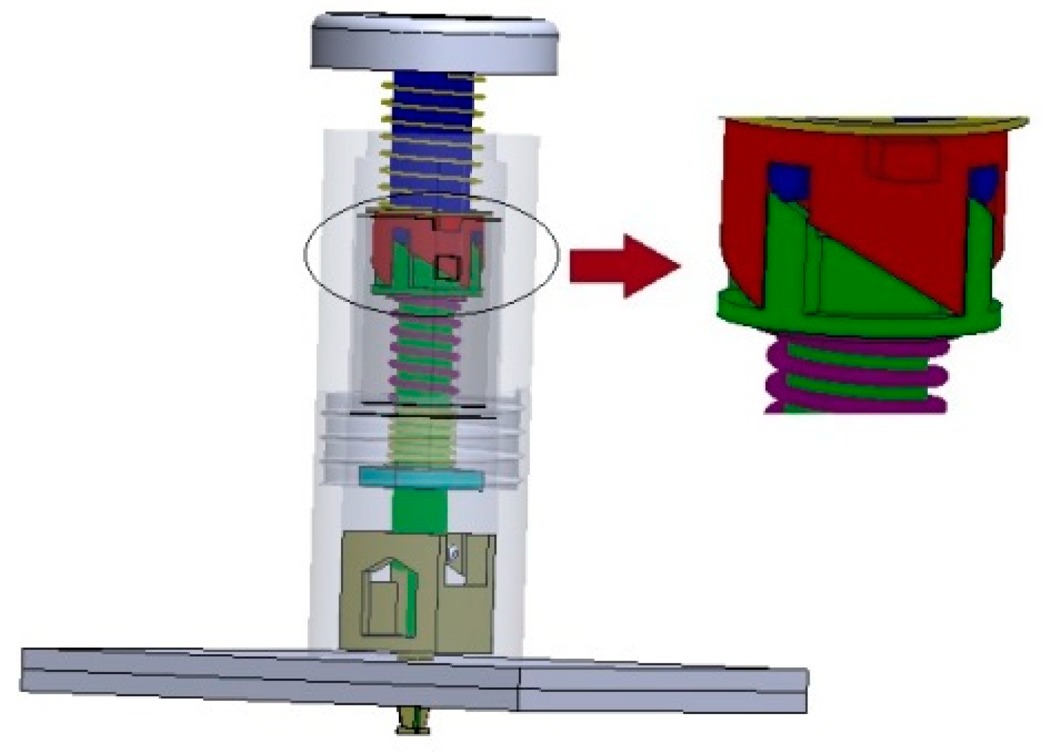
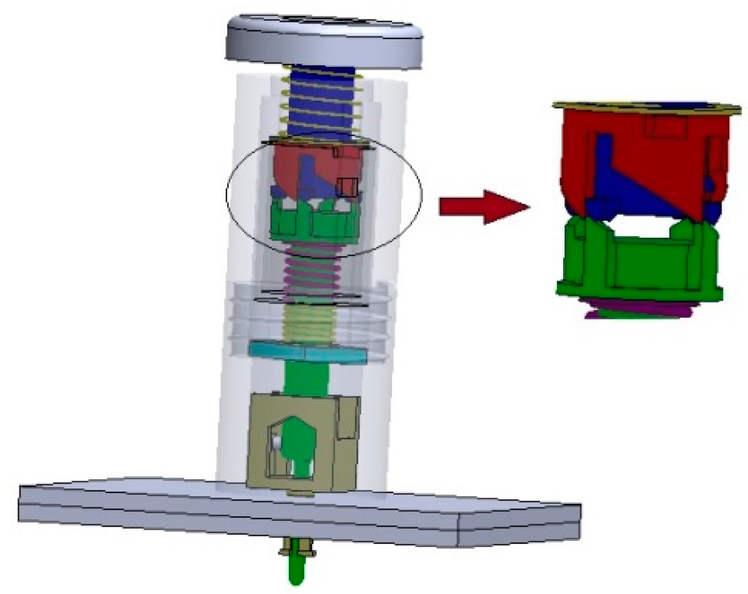
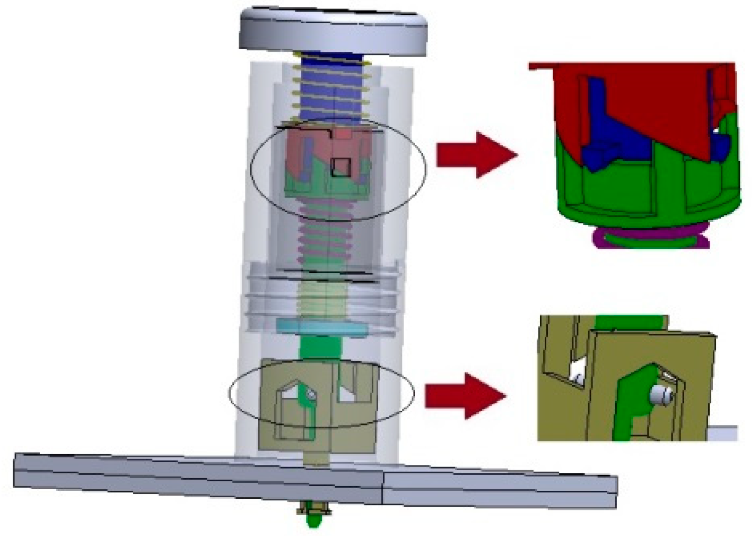
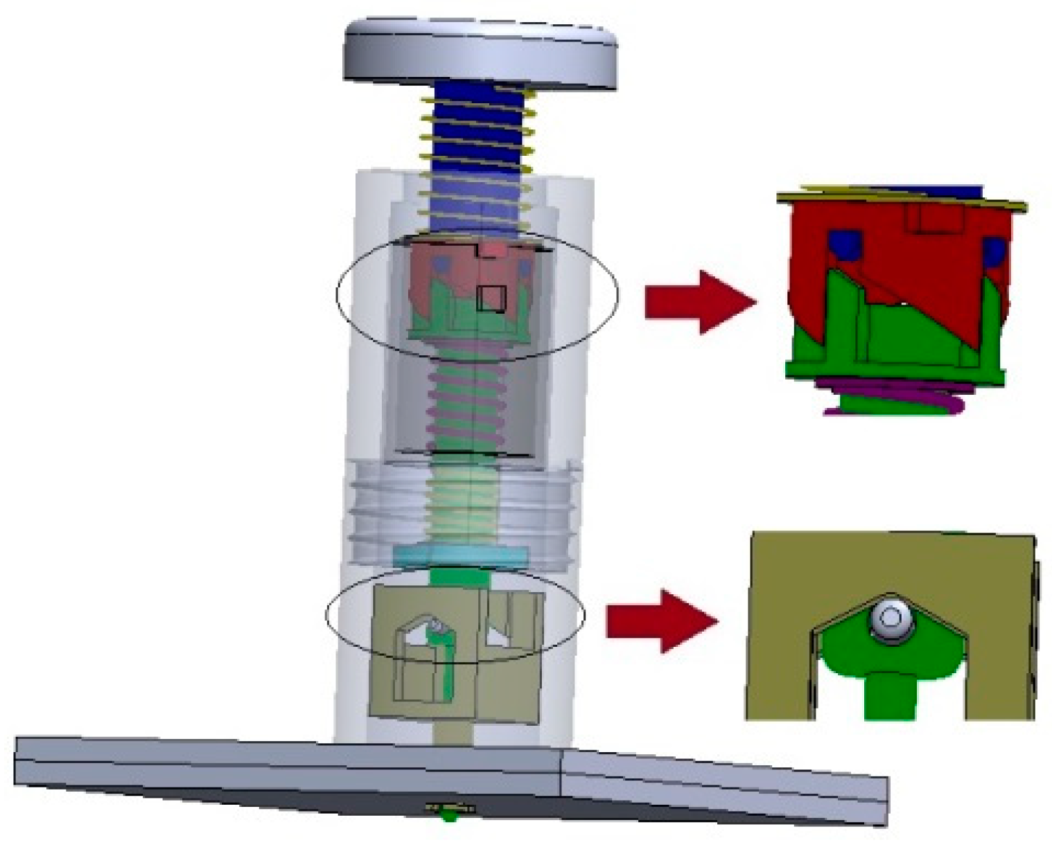
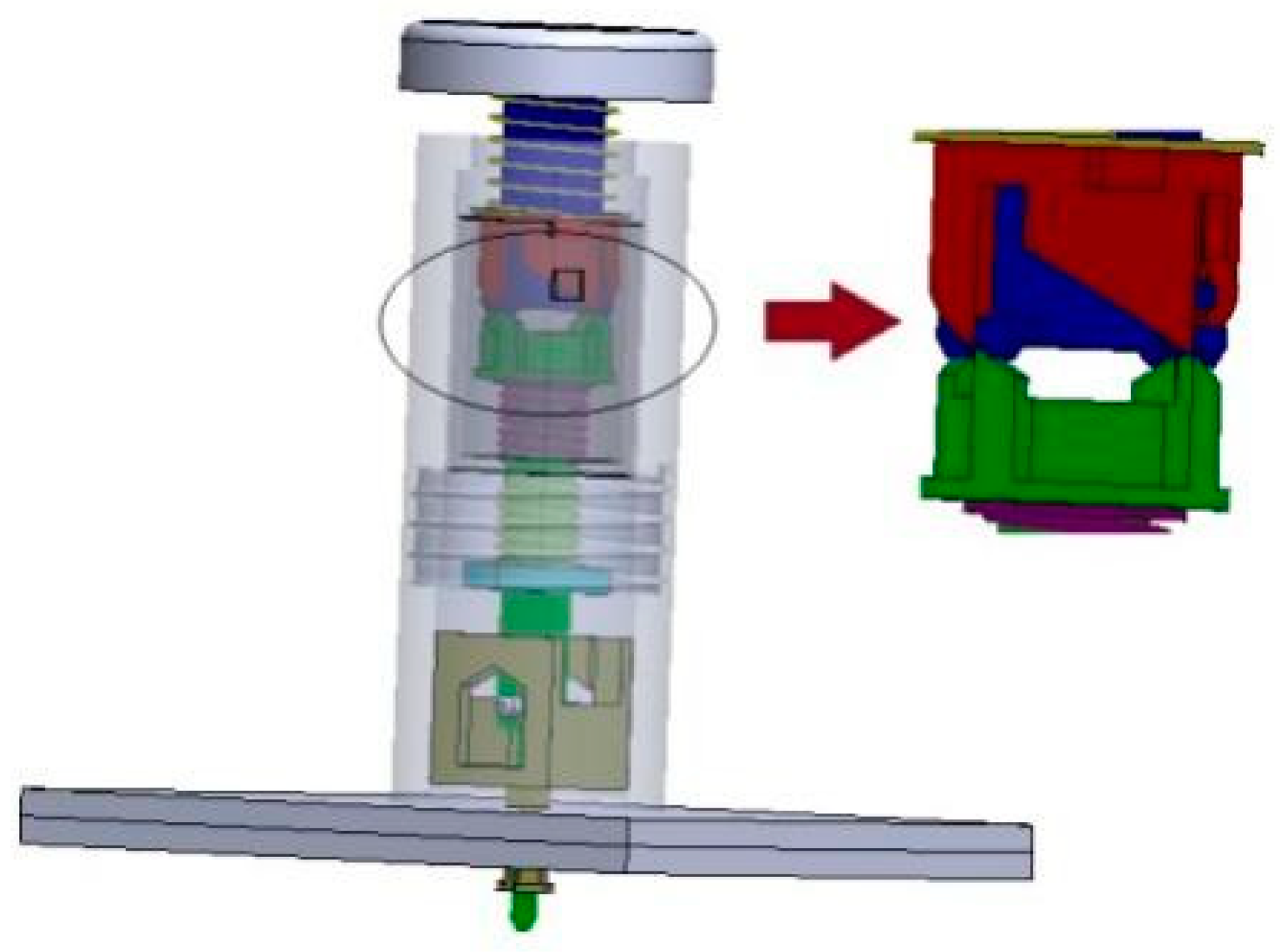
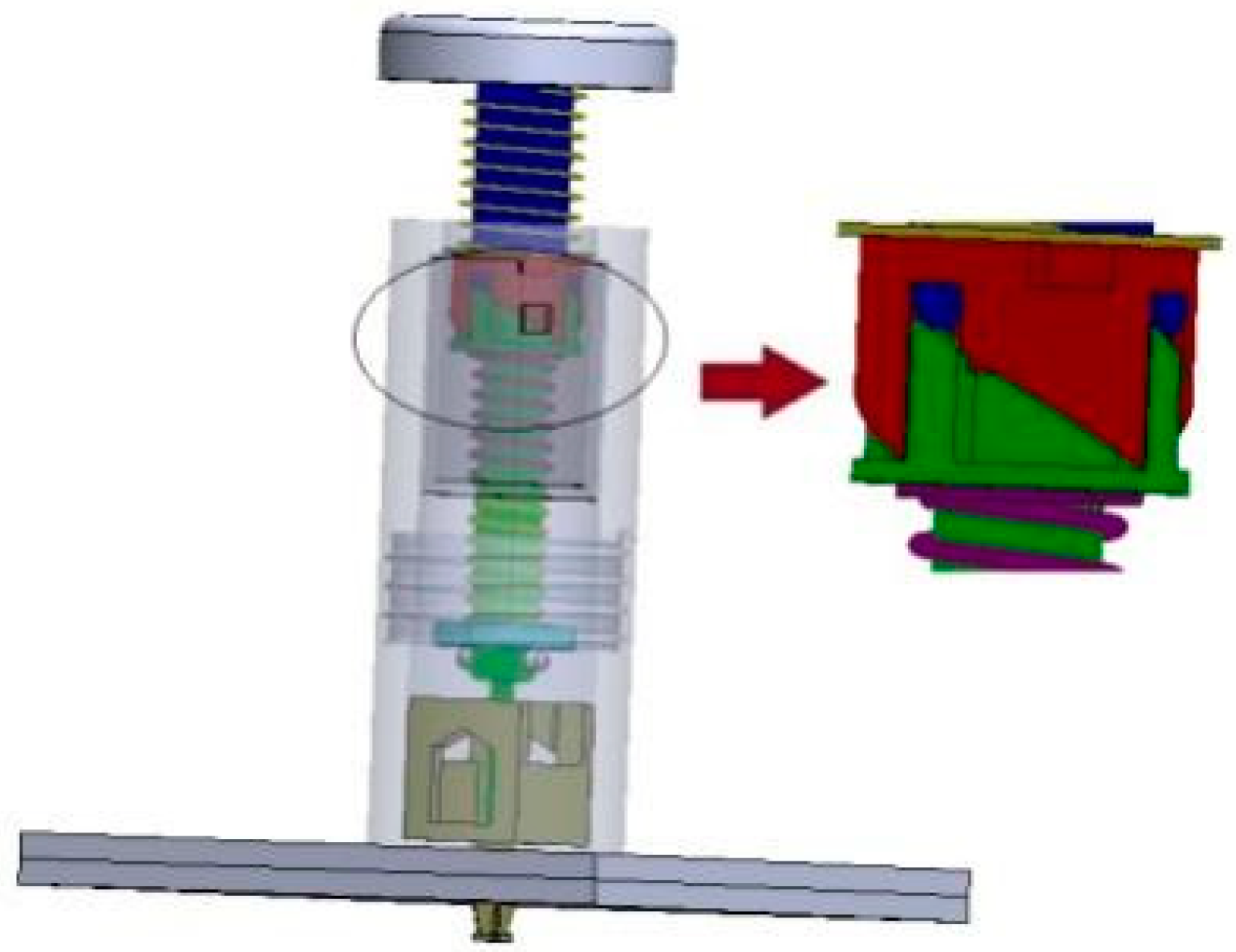
The specific steps of the temporary fastener installation-removal method for aircraft assembly in Figure 3, Figure 4, Figure 5, Figure 6, Figure 7 and Figure 8 are as follows:
(1)
As shown in Figure 3, insert a temporary fastener into the round hole and push the round button (2) forward. Then, the transmission assembly will slide forward at the same time, and the ejector spring (12) and the support spring (13) will be squeezed and compressed by the cylindrical top rod (11) and the inner sleeve (6), respectively. Afterwards, the mandrel retaining bar (14) will slide into the inside of the square groove of the clamping jaw (8).
(2)
Continue to push the round button (2) forward. The ejector spring (12) will begin to compress, the ratchet wheel (5) will be stationary relative to the inner sleeve, and the top of the cylindrical push rod (4) will be against the inclined surface of the cylinder top on the rod (11) and will move forward. The cylindrical top rod (11) will push out the four-petal claw structure with the taper barb of the clamping jaw to enlarge the taper section of the jaw. Its schematic is shown in Figure 4.
(3)
As illustrated in Figure 5, when the cylindrical top rod (11) moves beyond the groove of the ratchet wheel (5), it will begin to revolve. Hereafter, under the response force of the mandrel spring (12), it will rotate along the slope of the ratchet wheel (5), and the mandrel retention bar (14) will hook the clamping jaws (8) in the square grooves of the clamping jaws by turning.
(4)
As shown in Figure 6, release the round button (2), and the inner sleeve (6) will slide backwards and pass through the mandrel retaining bar (14) on the cylindrical push rod (11). Drive the clamping jaws to slide back axially so that the barbs on the four-petal jaws contact the connecting panels. The mandrel retaining bar will rotate 90°, and the connecting panels will be clamped.
(5)
When removing the temporary fasteners, press the round button (2) again, and the internal parts of the fasteners will repeat the previous installation movement procedure until the cylindrical plunger (11) rotates 90° to remove the mandrel holding bar (14) to depart from the jaws, as depicted in Figure 7.
(6)
When the spring response force is applied, the moving components will return to their original positions, the clamping claw structure will shrink back to its original shape, and the barb structure will loosen the connecting panels, as shown in Figure 8.
(7)
Repeat steps (1)–(6) for the installing and removing of other temporary fasteners.

3. Mechanical Relationship Analysis of Temporary Fasteners and Design of Key Parts

During the installation of the temporary fastener, the cylindrical top rod travels downward, owing to the application of the pressing force of the round button. When the rotation position of the cylindrical top rod occurs, the spring is squeezed to its maximum, which is the needed pressure force. Starting from the principle of mechanical equilibrium, to investigate the needed pressure force and clamping force, the critical point of the rotation of the cylindrical top rod and the final clamping condition are chosen for force analysis. Furthermore, the maximum force required to start the temporary fastener is calculated. The amount and magnitude of the clamping force is also calculated.

3.1. Critical State

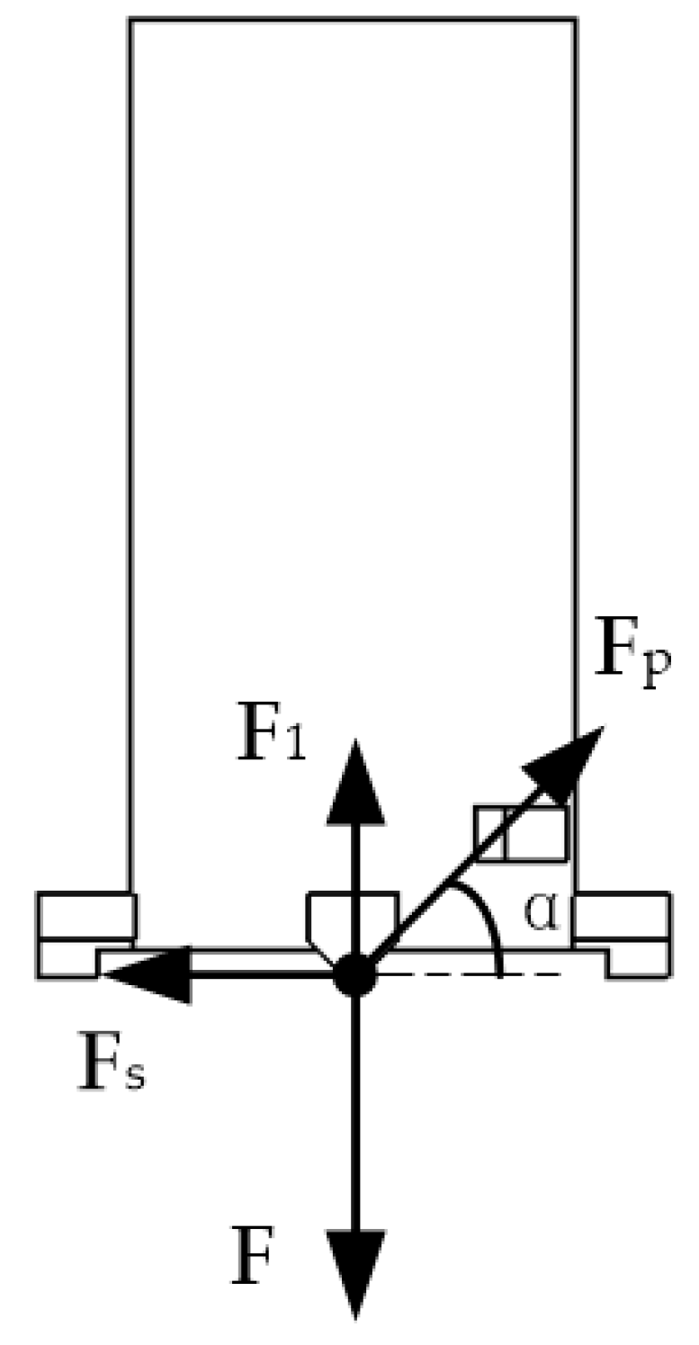
When the interior of the temporary fastener reaches the critical rotational state, as shown in Figure 9, the cylindrical top rod is going to slip into the ratchet groove and spin due to the action of the big and small springs. Because the gravity of the component has a minor influence on the movement process, gravity is ignored for simplicity of analysis. For the cylindrical push rod, we performed the following analysis, as illustrated in Figure 10.
  • F —Pressure force,
  • F 1 —The restoring force of the return spring,
  • F p —The tip of the cylindrical push rod receives the reaction force of the cylindrical top rod,
  • F s —Reaction force from ratchet chute,
  • α —The angle formed by the cylindrical ejector pin’s reaction force and the horizontal plane.
From the balance equation we obtained:
F = F p sin α + F 1
F s = F p cos α
Figure 11 shows the force diagram of the cylindrical top rod.
  • F 2 —The elastic force of the ejector spring,
  • F p —The inclined surface of the cylindrical ejector rod receives the reaction force of the cylindrical push rod,
  • F e —Ratchet chute reaction force,
  • θ —The angle between the inclined plane of the top of the cylindrical top rod and the vertical plane.
From the balance equation we obtained:
F 2 = F p sin θ
F e = F p cos θ
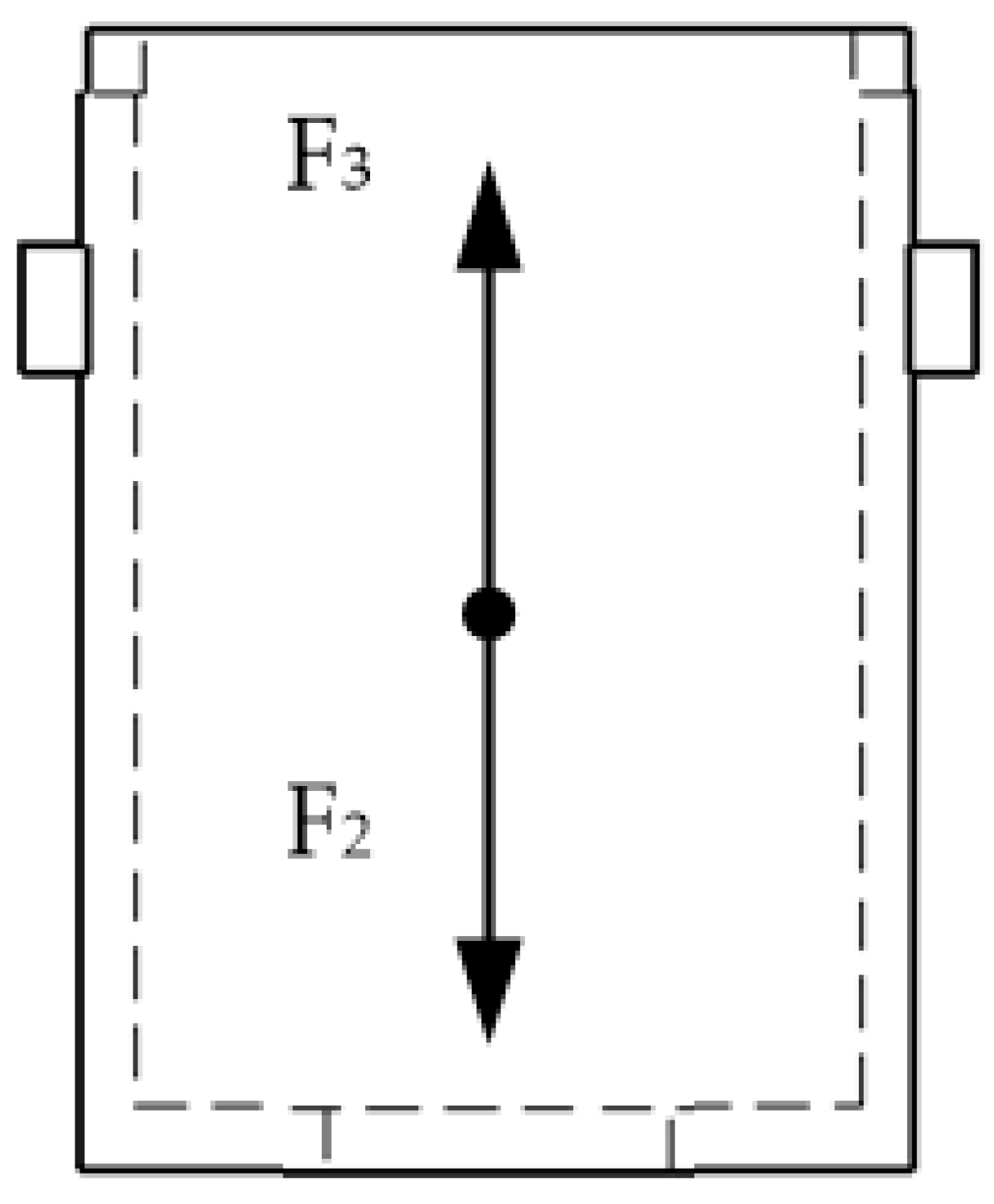
Figure 12 shows the inner sleeve’s force state.
  • F 2 —The elastic force of the ejector spring,
  • F 3 —The elastic force of the supporting spring,
  • F n —The reaction force of the ratchet.
From the balance equation we obtained:
F 3 = F 2 + F n
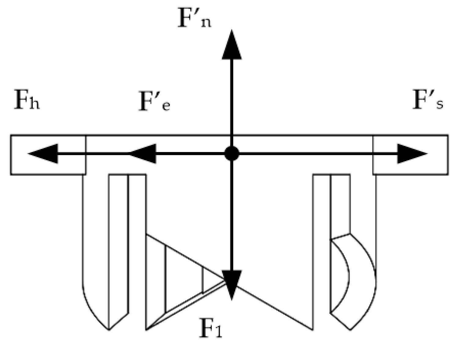
The force of the ratchet is shown in Figure 13.
  • F 1 —The restoring force of the return spring,
  • F n —Supporting force of the inner sleeve,
  • F s —Forces acting on the cylindrical push rod,
  • F e —Reaction forces of the cylindrical top rod,
  • F h —Supporting forces of the tail shell.
From the balance equation we obtained:
F 1 = F n
F h + F e = F s
In addition:
F n = F n
F p = F p
F s = F s
F e = F e
α = θ
The above equations can be combined to obtain Equation (13).
F = F 3 = F 1 + F 2
According to Hooke’s law, the following could be deduced:
k 3 · Δ x 3 = k 1 · Δ x 1 + k 2 · Δ x 2
where k 1 is the elastic coefficient of the return spring, k 2 is the elastic coefficient of the ejector spring, k 3 is the elastic coefficient of the supporting spring, Δ x 1 is the deformation of the return spring in the critical state, Δ x 2 is the deformation of the ejector spring in the critical state, and Δ x 3 is the deformation of the supporting spring in the critical state. Δ x 1 is the distance between the cylindrical push rod and the ratchet wheel, which is determined by the ratchet wheel’s size. It is a constant b , and the movement distance of the cylindrical push rod relative to the sleeve is also Δ x 2 = b .
Thus:
F = b ( k 1 + k 2 )

3.2. Clamping State

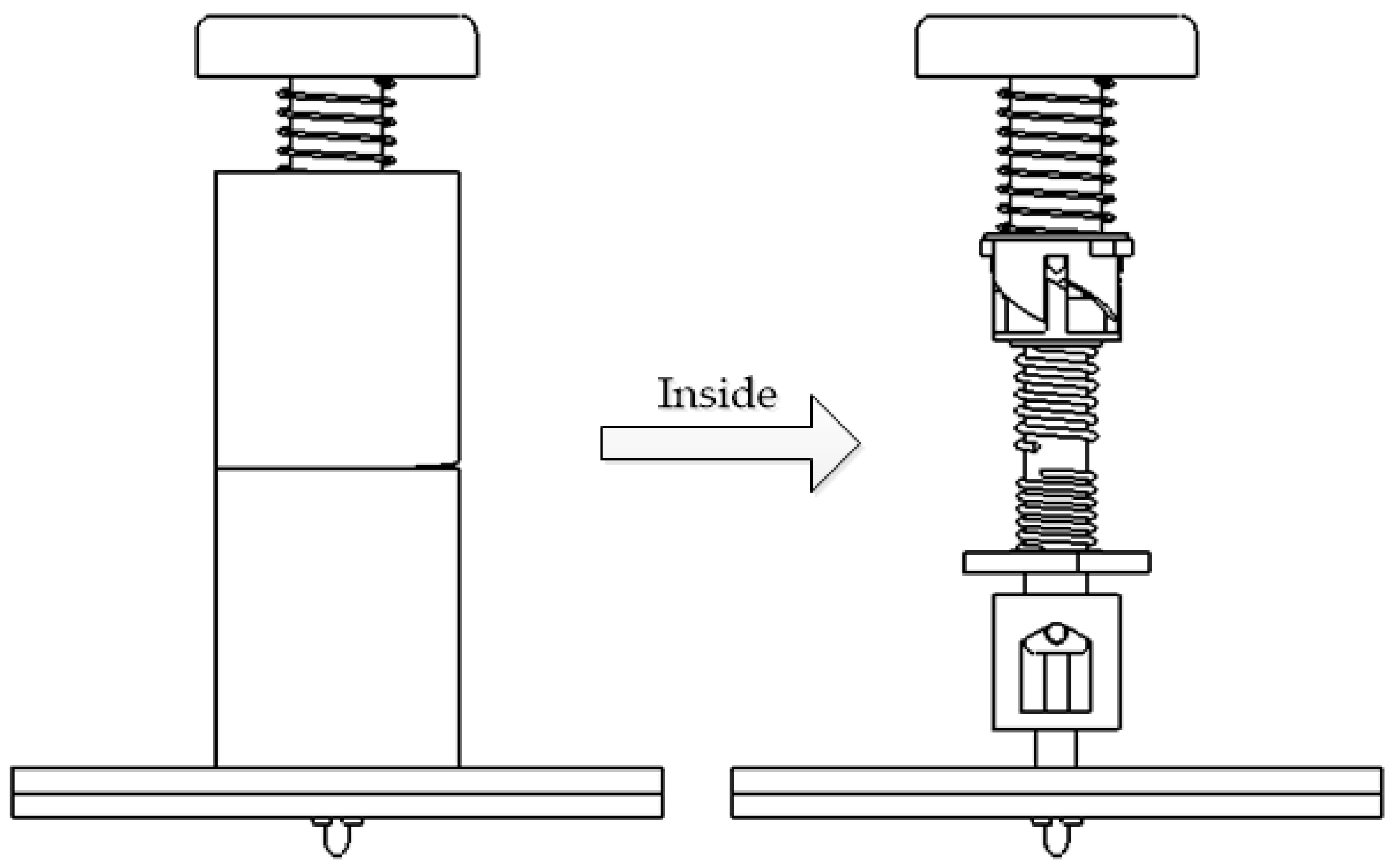
When the temporary fastener is fastened in Figure 14, the cylindrical ejector rod is tight and secured, due to the combined action of the ejector spring, supporting spring, and clamping jaw. The cylindrical push rod, ratchet wheel, and return spring are all free-floating. For simplicity of analysis, the gravity of the parts is ignored. Therefore, only the force analysis of the cylindrical top rod and the inner sleeve is performed here.
The force of the cylindrical top rod can be seen in Figure 15.
  • F 2 —The elastic force of the ejector spring,
  • F c —The clamping force of the connecting panels on the clamping jaw.
Thus:
F 2 = F c
The force relationship of the inner sleeve is illustrated in Figure 16.
From this diagram we acquired:
F 2 = F 3
Simultaneous equations result in:
F c = F 2 = F 3 = k 3 · Δ x 3
The schematic diagram is shown in Figure 17.
Because F 2 = F 3 ,
{ k 2 Δ x 2 = k 3 Δ x 3   l 1 + l 2 = L c Δ x 2 = h 1 l 1 Δ x 2 = h 2 l 2
In the above formula, l 1 is the length of the ejector spring in the clamped state, l 2 is the length of the supporting spring in the clamped state, h 1 is the free height of the ejector spring, h 2 is the free height of the supporting spring, L is the distance from the baffle plate to the bottom surface of the cylindrical top rod in the clamped state, and c is the thickness of the bottom of the inner sleeve.
Combining Formulas (19), we solve
{ l 1 = L c k 3 h 2 k 2 h 1 + k 2 ( L c ) k 2 + k 3 l 2 = k 3 h 2 k 2 h 1 + k 2 ( L c ) k 2 + k 3
Thus:
F c = k 2 k 3 ( h 1 + h 2 L + c ) k 2 + k 3

4. Example Verification

4.1. Experiment Materials and Device

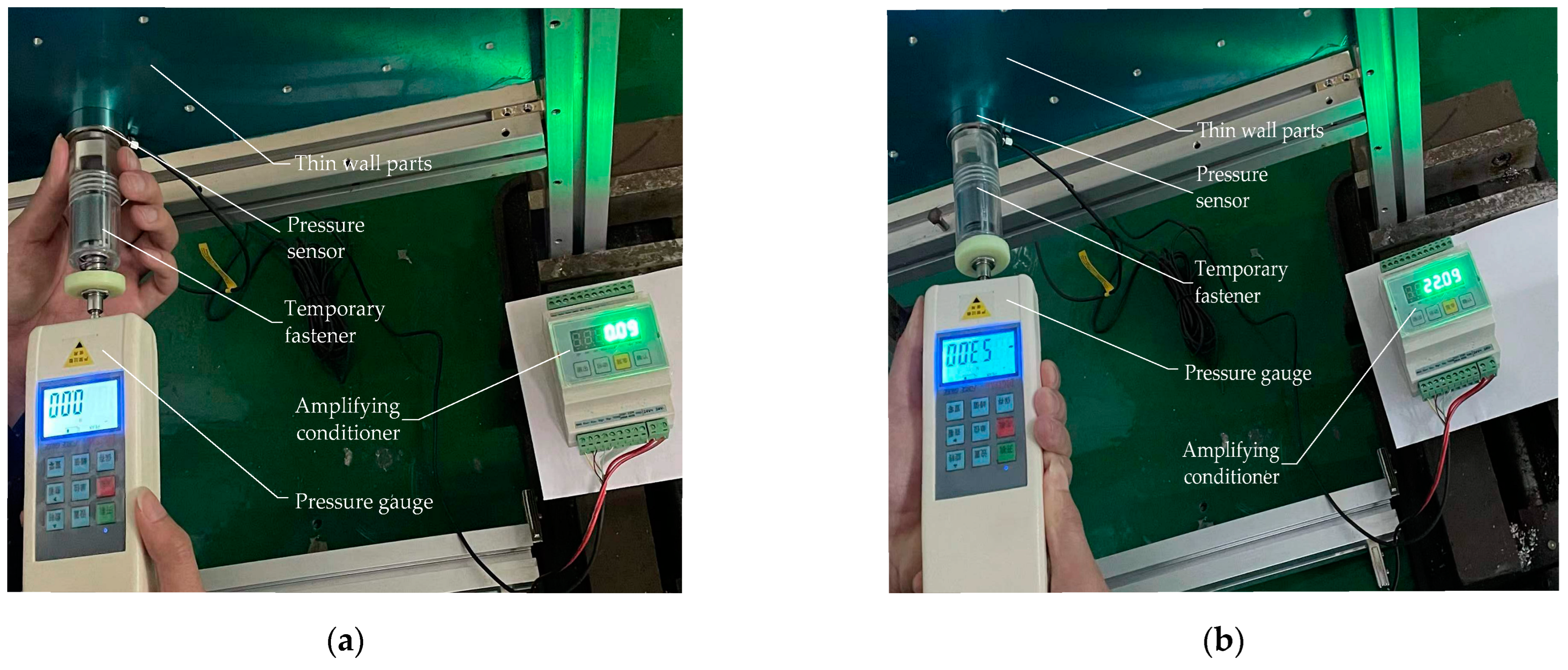
Figure 18a depicts the physical map of the experiment device after manufacture in accordance with the design drawings. The self-locking quick-press temporary fasteners were put on one side of two thin wall parts. These parts were composed of aluminum plate 7075, the same material as airplane plates. The experiment devices included one support frame, two aluminum plates, one pressure sensor, one amplifying conditioner, one 24 V power supply, one pressure gauge, and one quick-press and self-locking temporary fastener.
Ensuring the reliability of temporary fastener connections requires the careful selection of materials for component processing, which directly affects the smoothness of movement between parts. This is particularly important for clamping claw components, which require materials with a certain level of flexibility to ensure their ability to expand and contract as well as to prevent fatigue failure and fracture. Some scholars have conducted research on related materials [21,22,23]. According to a study by Rae et al. [24], the mechanical properties of PEEK 450 G were extensively investigated, including compressive, tensile, and Taylor impact properties, as well as large-strain compression tests and fracture toughness measurements. The study found that the mechanical response of PEEK 450 G is strongly dependent on strain rate and testing temperature. The authors also reported a previously observed darkening phenomenon in Taylor impacted samples, which was attributed to reduced crystallinity resulting from a large compressive strain. Additionally, the study found that reduced crystallinity was also found to decrease Vickers hardness. PEEK 450 G exhibits good toughness and can meet the basic requirements for temporary fastener clamping claw components. Springs are also vulnerable components that can be replaced at regular intervals or with higher-performance materials to effectively increase the service life of the fastener. Table 2 displays the necessary parameters of related parts. They were put together using aluminum profiles to form a support frame. In this experiment, a hole with a diameter of 5 mm was drilled into the thin wall parts, corresponding to the clamping jaw. Considering the influence of tolerance in assembly [25], the accuracy of this test hole is H8, to ensure that the claw part of the clamping claw can pass through the hole smoothly and that the claw can clamp the connecting plates when the claw taper expands.

4.2. Experiment Procedure

(1)
Put the two aluminum plates to be overlapped into the chute of the support frame so that the round holes of the front and rear aluminum plates correspond one by one.
(2)
Install the pressure sensor and the amplifier conditioner according to the circuit diagram and provide the 24 V power supply.
(3)
Turn on the power switch and set the value on the amplifier conditioner to zero.
(4)
Assemble the quick-pressing self-locking temporary fasteners, set the pressure sensor on the hole surface of the aluminum plates, insert the clamping claw through the circular hole, and concentrically press the pressure gauge and the fastener. The maximum value of the pressure gauge is recorded before the clamping jaw rotates.
(5)
Let the temporary fastener’s head shell stay tightly attached to the pressure sensor’s surface and reach the self-locking stage. Make a note of the values on the pressure gauge and the amplifying conditioner. Perform the above experiment five times to obtain the average value.

4.3. Experiment Results and Analysis

4.3.1. Theoretical Calculation

From the relative parameters of the springs we obtained:
k 1 = G d 8 n C 3 = 80,000 × 1.2 8 × 3 × ( 16 1.2 1.2 ) 3   N / mm = 2.13   N / mm
k 2 = F m a x 65 % h 1 = 40.2 65 % × 15   N / mm = 4.12   N / mm
k 3 = G d 8 n C 3 = 70,300 × 1.4 8 × 3 × ( 12 1.4 1.4 ) 3   N / mm = 9.45   N / mm
From Equation (15) and the actual measurement of b = 7.8   mm , the pressure force F can be calculated:
F = b ( k 1 + k 2 )   = 7.8 × ( 2.13 + 4.12 )   N = 48.75   N
Therefore, the theoretical pressure force is 48.75 N.
The actual measurements could be L = 24.2   mm , c = 1.55   mm , so the clamping force F c can be obtained from (21):
F c = k 2 k 3 ( h 1 + h 2 L + c ) k 2 + k 3 = 4.12 × 9.45 × ( 15 + 15 24.2 + 1.55 ) 4.12 + 9.45   N = 21.09   N

4.3.2. Experimental Data Analysis and Discussion

The measured results of the pressure gauge and pressure sensor are shown in Figure 18b.
After five experiments, the average value was taken to obtain the measured values. The measured values and the theoretical values for this example are illustrated in Table 3.
According to the experimental results, the fastener’s pressure force and clamping force are slightly different from the theoretical values. Because the theoretical analysis ignored the gravity and friction of the parts, and because there are some inaccuracies in manual measurement, the actual measured values are greater than the theoretical ones.
The experiment also showed that the fastener could achieve quick installation and removal, and a simple operation could achieve unilateral loading and unloading, which is conducive to automatic loading and unloading.
The advantages of the fastener are demonstrated in Table 4.

5. Conclusions

This article presents a novel, quick-pressing, self-locking temporary fastener designed for pre-joining aircraft wall panels. The working principles of the fastener are comprehensively calculated and explained, and its feasibility is experimentally validated.
(1)
This research has proposed a quick-pressing self-locking temporary fastener to address the issues of low work efficiency and the cumbersome installation of traditional bolts for panels. This fastener can not only carry out automatic bonding of thin-walled metal components, but it can also perform unilateral fastening and detaching.
(2)
The major components of this temporary fastener are theoretically calculated and statically analyzed. Aiming at the temporary connection of thin-walled plates with a large area, this temporary fastener is meant to achieve single-sided quick assembly and disassembly through the organic combination of a ratchet mechanism, clamping mechanism, and spring. After its analysis and verification, all parts satisfied work requirements under normal settings and proved the device’s practicality.
(3)
An experiment with a quick-pressing self-locking temporary fastener was performed. According to the results of the experiment, this temporary fastener had a high installation efficiency and could reach the required range of clamping force. Its movement status is essentially compatible with the established movement circumstances. The measured forces and the theoretical calculation values are both within a defined error range, with errors of 8.01% and 4.53%, respectively. The experiment results have shown that the temporary fastener could perform the tightening function, and its effect is close to the theoretical effect. Meanwhile, this fastener can perform unilateral operations, fast loading and unloading, recycling, and improving efficiency, which makes it suitable for large-scale application in automated panel manufacturing.
(4)
In addition to the assembly of thin-walled aircraft parts, this fastener can also be employed to assemble thin-walled vehicle parts. For example, after the sheet metal components have been positioned and clamped, fasteners are used to connect two or more sheet metal pieces in order to remove the gaps between or among the sheet metal parts, allowing the sheet metal parts to be welded.

Author Contributions

Conceptualization, W.T. and W.Q.; methodology, W.T.; validation, Y.X.; formal analysis, J.H.; investigation, J.H.; resources, C.L.; data curation, Y.X.; writing—original draft preparation, J.H.; writing—review and editing, W.T.; visualization, J.H.; supervision, J.Y.; project administration, W.T. and W.Q.; funding acquisition, W.T. and H.L. All authors have read and agreed to the published version of the manuscript.

Funding

This research was funded by School-level Scientific Research Project of Shaoguan University (No. SZ2020KJ12), National Natural Science Foundation of China (No. 51775495) and Scientific Research Project of Shaoguan University for Talent Introduction (No. 440-99000620).

Institutional Review Board Statement

Not applicable.

Informed Consent Statement

Not applicable.

Data Availability Statement

Not applicable.

Conflicts of Interest

The authors declare no conflict of interest.

References

  1. Jia, Z.; Bhatia, A.; Aronson, R.M.; Bourne, D.; Mason, M.T. A survey of automated threaded fastening. IEEE Trans. Autom. Sci. Eng. 2018, 16, 298–310. [Google Scholar] [CrossRef]
  2. Ranjan, B.S.C.; Vikranth, H.N.; Ghosal, A. A novel prevailing torque threaded fastener and its analysis. J. Mech. Des. 2013, 135, 101007. [Google Scholar] [CrossRef] [Green Version]
  3. Gong, H.; Ding, X.; Liu, J.; Feng, H. Review of research on loosening of threaded fasteners. Friction 2021, 10, 335–359. [Google Scholar] [CrossRef]
  4. Shan, Z.W.; Su, R.K.L. Behavior of shear connectors joined by direct fastening. Eng. Struct. 2019, 196, 109321. [Google Scholar] [CrossRef]
  5. Mourad, S. Behaviour of Blind Bolted Moment Connections for Square HSS Columns; McMaster University: Hamilton, ON, Canada, 1994. [Google Scholar]
  6. Sadri, S.M.; Plunkett, M.R.; Hicks, M.R. High Strength Blind Bolt with Uniform High Clamp over an Extended Grip Range. U.S. Patent US05603592A, 18 February 1997. [Google Scholar]
  7. Gang, L.; Tang, W.; Ke, Y.L.; Chen, Q.L.; Bi, Y.B. Modeling of fast pre-joining processes optimization for skin-stringer panels. Assem. Autom. 2014, 34, 323–332. [Google Scholar]
  8. Gang, L.; Tang, W.; Ke, Y.L.; Chen, Q.L.; Chen, X.M. Pre-joining process planning model for a batch of skin-stringer panels based on statistical clearances. Int. J. Adv. Manuf. Technol. 2015, 78, 41–51. [Google Scholar]
  9. Qu, W.W.; Tang, W.; Ke, Y.L. Pre-joining processes optimization method for panel orienting to the clearances suppression of units and the clearances flow among units. Int. J. Adv. Manuf. Technol. 2018, 94, 1357–1371. [Google Scholar] [CrossRef]
  10. Kim, C.; Bonjoon, G.; Moo, H.S.; Yi, S. Accurate Fastening of Blind Rivet Nuts: A Study. Trans. Mater. Process. 2020, 29, 331–337. [Google Scholar]
  11. Van de Velde, A.; Debruyne, D.; Maeyens, J.; Wevers, M.; Coppieters, S. Towards best practice in numerical simulation of blind rivet nut installation. Int. J. Mater. Form. 2021, 14, 1139–1155. [Google Scholar] [CrossRef]
  12. Klasztorny, M.; Nycz, D. Modelling and numerical study of blind rivet nut/bolt joints of composite shell segments. In Shell Structures: Theory and Application; CRC Press: Boca Raton, FL, USA, 2013; pp. 409–412. [Google Scholar]
  13. Studziński, R. Experimental investigation of the use of blind rivets in sandwich panels. J. Sandw. Struct. Mater. 2021, 23, 3669–3684. [Google Scholar] [CrossRef]
  14. Sun, L.; Liu, M.; Liu, Y.; Wang, P.; Zhao, H.; Sun, J.; Shang, Y. Studies on T-shaped one-side bolted connection to hollow section column under bending. J. Constr. Steel Res. 2020, 175, 106359. [Google Scholar] [CrossRef]
  15. Nikoukalam, M.T.; Mirghaderi, S.R.; Dolatshahi, K.M. Shear slotted bolted connection. Struct. Des. Tall Spec. Build. 2017, 26, e1313. [Google Scholar] [CrossRef]
  16. Nakajima, K.; Suzuki, H.; Kawabe, Y.; Fujii, K. Experimental Study on High Strength One-Side Bolted Joints; Taylor & Francis Group: London, UK, 2012. [Google Scholar]
  17. Vilela, P.M.L.; Carvalho, H.; Baião, O.T. Numerical simulation of bolted connections. Lat. Am. J. Solids Struct. 2018, 15, e94. [Google Scholar] [CrossRef] [Green Version]
  18. Ungermann, D.; Luebke, S. Innovative fastening of sandwich panels in one face sheet only. STAHLBAU 2012, 81, 912-U112. [Google Scholar] [CrossRef]
  19. Xu, F.; Cai, Y.; Chan, T.M.; Young, B. Tube wall deformation behaviour of tensile-loaded blind-bolted connections in octagonal hollow section tubes. Thin-Walled Struct. 2023, 184, 110447. [Google Scholar] [CrossRef]
  20. Tang, W.; Xie, X.; Ye, Y.K.; Qu, W.W. Design of a Fast Temporary Fastener with the Labor-Saving and Reversible Ability. Coatings 2021, 11, 1101. [Google Scholar] [CrossRef]
  21. Wang, W.; Hua, D.; Zhou, Q.; Li, S.; Eder, S.J.; Shi, J.; Wang, Z.; Wang, H.; Liu, W. Effect of a water film on the material removal behavior of Invar during chemical mechanical polishing. Appl. Surf. Sci. 2023, 616, 156490. [Google Scholar] [CrossRef]
  22. Ye, W.; Xie, M.; Huang, Z.; Wang, H.; Zhou, Q.; Wang, L.; Chen, B.; Wang, H.; Liu, W. Microstructure and tribological properties of in-situ carbide/CoCrFeNiMn high entropy alloy composites synthesized by flake powder metallurgy. Tribol. Int. 2023, 181, 108295. [Google Scholar] [CrossRef]
  23. Jia, Q.; He, W.; Hua, D.; Zhou, Q.; Du, Y.; Ren, Y.; Lu, Z.; Wang, H.; Zhou, F.; Wang, J. Effects of structure relaxation and surface oxidation on nanoscopic wear behaviors of metallic glass. Acta Mater. 2022, 232, 117934. [Google Scholar] [CrossRef]
  24. Rae, P.J.; Brown, E.N.; Orler, E.B. The mechanical properties of poly(ether-ether-ketone) (PEEK) with emphasis on the large compressive strain response. Polymer 2007, 48, 598–615. [Google Scholar] [CrossRef]
  25. Sadowski, T.; Golewski, P. Effect of Tolerance in the Fitting of Rivets in the Holes of Double Lap Joints Subjected to Uniaxial Tension. In Key Engineering Materials; Trans Tech Publications Ltd.: Zurich, Switzerland, 2014; Volume 607, pp. 49–54. [Google Scholar]
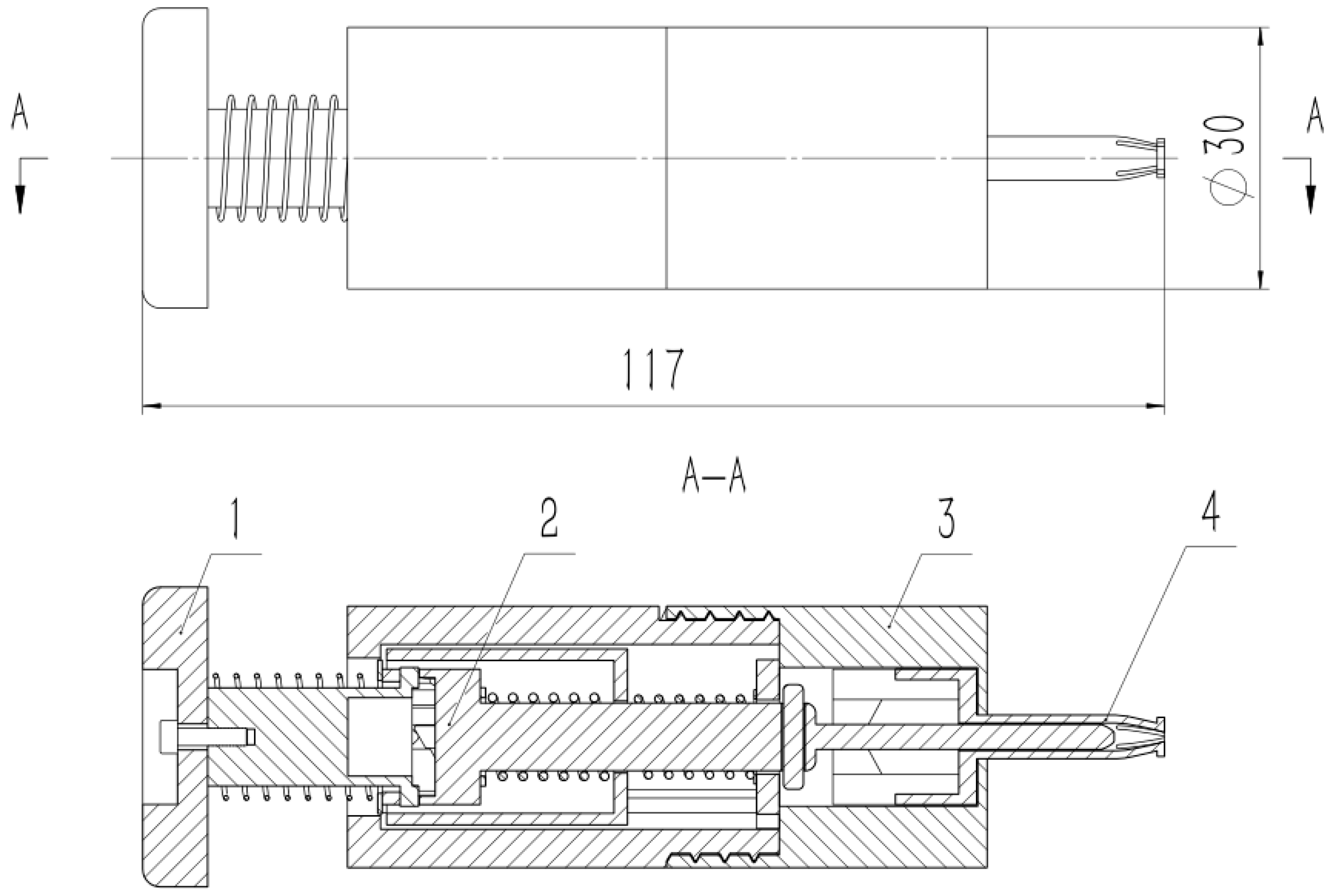
Figure 1. The overall structure of quick-press self-locking temporary fasteners. 1—Button, 2—Transmission assembly, 3—Shell, 4—Clamping assembly.
Applsci 13 03004 g001
Figure 2. Exploded view of quick-press self-locking temporary fasteners. 1—Screw, 2—Round button, 3—Tail shell, 4—Cylindrical push rod, 5—Ratchet wheel, 6—Inner sleeve, 7—Baffle, 8—Clamping claw, 9—Head shell, 10—Return spring, 11—Cylindrical top rod, 12—Spring of ejector rod, 13—Supporting spring, 14—Mandrel retaining bar.
Applsci 13 03004 g002
Figure 3. Schematic diagram of step 1.
Applsci 13 03004 g003
Figure 4. Schematic diagram of step 2.
Applsci 13 03004 g004
Figure 5. Schematic diagram of step 3.
Applsci 13 03004 g005
Figure 6. Schematic diagram of step 4.
Applsci 13 03004 g006
Figure 7. Schematic diagram of step 5.
Applsci 13 03004 g007
Figure 8. Schematic diagram of step 6.
Applsci 13 03004 g008
Figure 9. Critical state of temporary fastener.
Applsci 13 03004 g009
Figure 10. Force diagram of cylindrical push rod.
Applsci 13 03004 g010
Figure 11. Force diagram of cylindrical top rod.
Applsci 13 03004 g011
Figure 12. Force diagram of the inner sleeve.
Applsci 13 03004 g012
Figure 13. Force diagram of ratchet.
Applsci 13 03004 g013
Figure 14. Clamping state of temporary fasteners.
Applsci 13 03004 g014
Figure 15. Force relationship of the cylindrical top rod.
Applsci 13 03004 g015
Figure 16. Force relationship of the inner sleeve.
Applsci 13 03004 g016
Figure 17. Schematic diagram of the inner sleeve and the cylindrical top rod in the clamping state.
Applsci 13 03004 g017
Figure 18. (a) The physical diagram of the experiment device; (b) Experimental measured results.
Applsci 13 03004 g018
Table 1. Functions and corresponding innovative structures.
Functional InnovationStructure Innovation
Quick-pressThe spring and cylindrical push rod closely cooperate with the ratchet.
Convenient for automated installationThe cylindrical-shape surface of the parts are the same.
Self-lockingCoordination between the mandrel retaining bar and the clamping jaw
Unilateral loading and unloadingClamping jaws structure with elastic
Table 2. Main parameters of parts.
Main PartsMaterialRelated Size
Thin wall partsAluminum alloy 7075length 800 mm width 500 mmthickness 2.5 mm
Cylindrical top rodStainless steel 316 Llength 80 mmmaximum diameter 15.52 mmminimum diameter 2.85 mm
Supporting springStainless steel 304external diameter 12 mminternal diameter 9.2 mmFree-height 15 mmEffective laps 3 laps
Spring of ejector rodalloy steel 55CrSiexternal diameter 12.5 mminternal diameter 8.5 mmFree-height 15 mmUltimate pressure 40.2 NUltimate compression rate 65%
Return springSpring steelexternal diameter 16 mminternal diameter 13.6 mmFree-height 20 mmEffective laps 3 laps
Body of fastenerResin r4600maximum length 115.5 mmminimum length 109.4 mmdiameter 30 mm
Clamping clawPEEK-450 Glength 15.5 mmwidth 15.5 mmheight 38 mm
Table 3. Comparison of results.
ForcesMeasured Value/NTheoretical Value/NError Rate
Pressure force F 53.0048.758.01%
Clamping force F c 22.0921.094.53%
Table 4. Advantages of fastener.
ReuseUnilateral OperationSelf-Locking
Adopt a four-petals claw structure with elastic, which can be recycled.Only need to press one button continuously to realize clamping and uninstalling.Coordination among the spring, the clamping jaw and shell with buckle, to hold the claw firmly.
Disclaimer/Publisher’s Note: The statements, opinions and data contained in all publications are solely those of the individual author(s) and contributor(s) and not of MDPI and/or the editor(s). MDPI and/or the editor(s) disclaim responsibility for any injury to people or property resulting from any ideas, methods, instructions or products referred to in the content.