Article

An Analysis of the Process of Applying Technical Lubricating Coatings

by
Marek Ochowiak
1,2,*,
Klaudia Werowska
1,
Andżelika Krupińska
1,
Magdalena Matuszak
1,
Sylwia Włodarczak
1 and
Zdzisław Bielecki
2,3
1
Department of Chemical Engineering and Equipment, Poznan University of Technology, 60-965 Poznan, Poland
2
Kuncar S.A., Pszczyńska 167C, 43-175 Wyry, Poland
3
Department of Automatic Control and Robotics, Silesian University of Technology, Akademicka 2A, 44-100 Gliwice, Poland
*
Author to whom correspondence should be addressed.
Appl. Sci. 2023, 13(5), 2983; https://doi.org/10.3390/app13052983
Submission received: 5 February 2023 / Revised: 23 February 2023 / Accepted: 24 February 2023 / Published: 25 February 2023

Abstract

:
The results of research on the process of applying lubricating coatings are presented in this work. For this purpose, plastic greases were used, in which the base oil is perfluoropolyether (PFPE) and the thickener is poly(tetrafluoroethylene) (PTFE). Due to their consistency, these materials are classified into different classes according to the National Lubricating Grease Institute (NLGI). The research was carried out using a time-pressure valve at varying atomization pressure values. Based on the obtained results, the width of the obtained material path and the angle of spray atomization were determined. The research indicated linear relationships between the atomization pressure and the degree of uniformity of the obtained spray.

1. Introduction

The process of applying technical lubricating coatings using liquid lubricants is essential in various industries to improve the performance and extend the service life of components. In various industrial sectors, machine parts often require low friction and high wear resistance in order to increase efficiency and the service lifetime of the infrastructure [1,2]. These coatings provide a barrier against wear, corrosion, and abrasion, and can reduce friction and wear to increase efficiency and reduce maintenance costs. Liquid lubricants are commonly used for applying these coatings due to their ability to easily flow and conform to the surface of the component. There are various methods for applying lubricating coatings using liquid lubricants, including dipping, brushing, and spraying. Each method has its own advantages and disadvantages, and the most suitable method will depend on the specific application and requirements [3].
Greases using perfluoropolyether (PFPE) as their base oil, and polytetrafluoroethylene (PTFE) as thickeners have found favor in industry, in applications where temperature exposures reach up to 300 °C. Conventional greases will typically not withstand such high temperatures as they will oxidize, burn, form deposits, or drop within a short exposure. Damaged bearings or machine components usually follow, or, in order to prevent such an occurrence, end-users may re-lubricate too frequently to compensate. Solid lubricating materials have become a popular alternative to liquid lubricants and grease due to their ability to reduce maintenance costs and environmental impact. They are also useful in applications that do not allow for external lubrication, such as in the aerospace, food, and medical industries. The most commonly used solid lubricant is PTFE which is known for its resistance to chemical attacks, high melting point, and biocompatibility [4,5]. PTFE has a low dry sliding friction coefficient on various counterface materials due to its low shear strength and the transfer of polymeric material to the counter surface, allowing for the sliding of two soft polymeric surfaces [6].
PTFE is known for its excellent sliding properties, but it has poor wear resistance and undergoes excessive viscoelastic deformation under load, which limits its use in high load-bearing applications [7]. To address these issues, various reinforcing fillers have been incorporated into PTFE, including inorganic materials such as metals and metal oxides/carbides, and organic materials such as carbon fiber, graphite, and polymer blends [1,8,9]. While these fillers can improve wear resistance and increase load capacity, there are often issues with corrosion when metal fillers are used and relatively low pressure-velocity limit values in purely polymeric composite systems. Thermal spray methods are used in various industrial sectors, including renewable/non-renewable energy divisions and the biomedical, automotive, and aerospace industries, due to their ability to form dense, wear-resistant coatings with strong mechanical adhesion to substrates [10].
Modern PFPE oils are liquids with a unique structure and properties [11]. Only three elements make up these substances: carbon, oxygen, and fluorine atoms. Strong bonds join the atoms, and the whole polymer chain is very elastic. The C-F bond is the strongest interatomic bond known in nature, and, simultaneously, fluorine is the most electronegative element, so the molecule is exceptionally durable. The lack of hydrogen, the common element of all standard liquid lubricants, contributes to the thermo-oxidizing stability of PFPE oils [12]. The substances have some unique properties [12,13]. PFPE are low-surface-tension liquids that are commonly employed, e.g., in magnetic recording devices as disk lubricants [14]. PFPE exhibits characteristics that outperform mineral oils, as well as common synthetic oils such as PAOs (polyalphaolefins) and esters. A modern approach to the formulation of PFPE lubricants enables obtaining new products with better properties than traditional ones. At the same time, it is possible to obtain new applications. Currently, it is observed that PFPE dual-purpose greases are increasingly replacing the commonly used PTFE/PFPE greases in applications where the operating temperature is ≤220 °C, or short-term ≤+250 °C [15].
PTFE and PFPE can be combined to form a grease that exhibits their strengths, outperforming mineral-oil based greases [16]. Grease applications for PTFE/PFPE include the lubrication of conveyor bearings that pass through ovens, such as in baking, wafer-making, and the painting of metals [17,18]. From the point of view of protecting components and machine parts, it is important to obtain a uniform lubricant surface on the component and to completely cover it. For this reason, the method of its application/spraying is important.
To determine the usefulness of plastic lubricants in industrial processes, one must use the classification of plastic lubricants created by the National Lubricating Grease Institute (NLGI). The criterion for this classification is the consistency, specifically the range of grease penetration after compression. Table 1 shows this classification [19]. Among lubricants, we can distinguish: mineral oils, synthetic oils, vegetable oils, plastic lubricants, solid lubricants, adhesive agents, emulsions, and special lubricants. Mineral and synthetic oils can be refined or unrefined. Solid lubricants include powders, pastes, or lacquers [20]. Adhesive agents include bituminous lubricants. The used emulsions are those with an oil-in-water or water-in-oil structure. Water, acids, or gases are classified as special lubricants [21].
The composition of plastic lubricants, specifically the proportions and type of ingredients used, has a significant impact on their properties. Even small changes in this area can result in significant modifications. The base oil (main component), which constitutes between 70% and 90% of the product, greatly influences the tribological properties of the lubricants [22,23]. Studies have shown the importance of the type of base oil used. Among the analyzed lubricants, the best performance was found with a plant-based dispersing base, which showed high efficiency in terms of protection against friction and wear. Mineral oil does not guarantee adequate anti-seize protection, despite guaranteeing anti-wear protection. Synthetic oils showed very low anti-friction properties and were twice as weak in anti-wear properties compared to mineral or plant-based oils. The important parameters that determine the tribological properties of the resulting compositions are the viscosity of the dispersion phase and the reaction occurring between the friction surface and the plastic lubricant, which precisely determines the significant impact of the products of this reaction [22].
The structure of plastic grease is determined by the type of thickener and its particle size. To increase the ability to rebuild the grease structure, a polymer additive (e.g., PTFE) should be added for mineral greases. Talc performs the same function in synthetic-based greases [24,25]. The functional additives of lubricants ensure their operational durability. It has been found that the most optimal anti-wear conditions are guaranteed by the simultaneous use of greases with a polymer additive and fullerene nanostructures of carbon. This conclusion was drawn on the basis of a comparison with grease with one additive [24]. Temperature can be an intensifying factor for the action of additives, which directly affects node protection [26,27].
Most lubricants produced have durability at a temperature of 80 °C. They are able to work in these temperature conditions for even several thousand hours. If the temperature at which they are used increases, their structure often degrades and they lose their properties. For example, one of the basic ingredients of such a lubricant may undergo oxidation, which reduces its durability to only a few hours at a temperature of 150 °C. It is a fact that the durability of a lubricant is inversely proportional to the temperature at which it is used—the higher it is, the more its durability significantly decreases. In addition, an increase in the temperature of the lubricant may be caused by bearing load. The result of an increased load is a higher temperature and a reduction in the rotational speed of the bearing. In such a situation, choosing lubricants of a different consistency class or with improved parameters is the solution [28].
It is not advisable to use plastic lubricants at low temperatures; however, some situations require the use of lubricants with increased resistance to negative temperatures. This occurs, for example, in aviation, where the plastic lubricants used have a durability at a temperature of −54 °C. Their use is safe due to the low-temperature melting synthetic base fluid [29]. Consistency is a parameter that informs us about the stiffness of the lubricant. In engineering solutions, it can be stated that the lubricant has been correctly selected for a specific application if, during the operation of the bearing or other element, it does not expose adjacent parts to increased friction [28].
Increasing production rates, minimizing set times, and maximizing savings on expensive coatings and lubricants are a few objectives processors strive to achieve when choosing an automated lubrication or coating spray system. The spray nozzles can be utilized to coat chains, conveyors, and trays with minimal waste [30]. Another major concern for processors is that of overspray. Eliminating overspray is not only beneficial to operations, but also to the health and safety of workers. The overspray that drips off from conveyors and surrounding equipment can spill onto the floors which poses a dangerous risk for workers. One of the many benefits of using atomizers is that they are able to apply coatings and lubricants with high accuracy, which leads to reducing or eliminating overspray altogether and decreased waste of costly coatings and lubricants, which ultimately leads to increased savings for the operator. In the food industry, a spray system is ideal for pan coating and other bakery and snack coating applications. The system can also be used for rolled metal lubrication applications. Beverage can lubrication, stamping, and general industrial applications all require a system that is able to coat with a heated lubricant. In addition, the spray systems are ideal for applying lubricants and corrosion protection fluids to blanks, coils, pipe sections, stamping and forming tools, wires, bars, and more [31]. Furthermore, to select a spray system that improves efficiency, many manufacturing plants are looking to use systems which are able to reduce their company’s environmental impact. Using a spray system that is able to control and precisely apply lubricants can reduce liquid consumption by up to 90% [32].
There are many methods of applying coatings; among the most important one that should be mentioned is various methods of spraying. The operation is the better one if the desired, stable effect can be obtained at lower investment costs. The authors of the article [33] showed that simple air-spraying gives well-performing solid lubricating coatings with better friction and wear properties for WS2 compared to Bi2S3, even at an elevated temperature of 200 °C. It is a much better solution than plasma spraying.
In this work, the process of applying technical lubricating coatings using liquid lubricants will be analyzed and discussed. The aim of the work was a comparative analysis of the process of applying technical coatings that were plastic lubricants. Using a pressure-time valve, material tracks were sprayed. The influence of atomization pressure, the geometry of the nozzles used, and the properties of the plastic greases used on the width of the obtained material track and the angle of the spray was studied.

2. Materials and Methods

2.1. Experimental Set-Up and Materials

The experimental set-up, which was used to apply the materials being tested to the surface, included: time-pressure valve 781S-SS (manufacturer Nordson EFD); nozzles (Nordson EFD 7856F-46SS 0.046″ and Nordson EFD 7856-46SS 0.046″); Nordson EFD Valve Mate 7140 regulator; pressure regulator; a material reservoir in the form of an applicator from which material is introduced into the system; and 3-axis robot. A simplified diagram of the measurement station is shown in Figure 1 [34]. To record the spray obtained and also the angle of atomization, which was necessary for further computer image analysis, the following were used: Canon EOS-100D camera; and USB Dino Lite AM3113T digital microscope.
Two plastic lubricants were used to create the coatings. These were PFPE fluorine lubricants, which had a number of advantages. They were resistant to loads and aggressive environmental conditions and had good thermal conductivity. These lubricants are used in precision mechanisms, at low temperatures. They are widely used in the electronic, electromechanical, chemical, and automotive industries. They are particularly used in the production of various types of seals, fittings, connectors, valves, and micro-mechanisms. The characteristics of the lubricants used are shown in Table 2 [35].
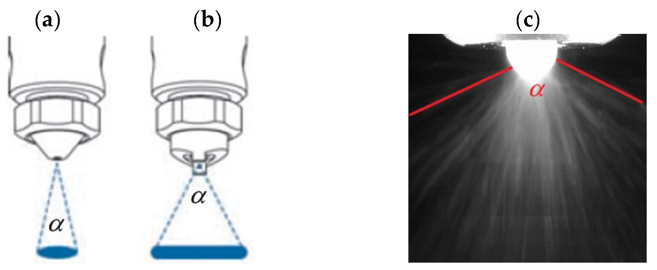
The Nordson EFD 781S series valve is part of a group of time-pressure valves. It is used for spraying small volumes of low-pressure lubricants. It creates an even coating of material with low to medium viscosity. Using this valve, the applied material path on the entire surface has the same thickness, without clogging, dripping, or drying of the material in the device. The spray itself occurs without material splash or mist. It is used for spraying substances such as lubricants, inks, and oils. Depending on the nozzle used, despite the same diameter of the outlet holes of the valve, different material/lubricant path can be obtained: a fan-flat spray for Nordson EFD 7856F-46SS 0.046″ (A) or a full cone spray for Nordson EFD 7856-46SS 0.046″ (B) (Figure 2) [34]. Using the 781S-SS series valve, the spray cycle rate can exceed 400 per minute. The maximum material pressure that can be obtained is 20.7 (bar), or 300 (psi), while the maximum operating temperature is 102 °C [35].

2.2. Methods

The first step was to set process assumptions. One of the most important was to achieve the greatest uniformity of the sprayed material layer. In addition, an important aspect was the smallest amount of material dust outside the intended spray path.
To make the process repeatable, it was necessary to use a constant linear valve speed of 120 mm/s in each measurement series, as well as a constant distance of the nozzle from the sprayed surface, equal to 10 mm. An important parameter was the amount of sprayed material, or the dose applied to the substrate each time. It was 7.5 g/min, and to obtain the required flow in the valve at this level, calibration was performed, which was carried out in the following steps:
Setting constant process parameters;
Modifying the material flow as needed by adjusting the degree of valve opening, i.e., needle lift, by adjusting (microadjust);
Re-regulating the material flow by changing the material pressure from 4 bar to 4.4 bar;
Dosing material into a controlled vessel for 10 s;
Measuring the weight of the dosed material;
Performing calculations to check the flow in 60 s.
Two nozzles with different designs were used in the study to compare how their geometry affects the obtained spray, with the outlet hole diameter always the same. It was 0.046 in. In addition, the impact of lubricants classified into different NLGI classes was compared, as well as the impact of variable atomization pressure in the range of 20 to 80 psi. Four measurement series were performed: two series for the full cone spray nozzle, and two series for the fan-flat spray nozzle for both lubricants (Table 3).
The photographic method was used to analyze the obtained spray path as well as the angle of the lubricant spray. This method is a basis for applying computer image analysis, which can be helpful in controlling plastic lubricants [36]. To take photos of the applied paths, a Canon digital SLR camera, Canon EOS-100D, was used. It was mounted on a compatible tripod to maintain identical operational conditions during photography. Standard camera settings were applied. The spray was applied to a black substrate to facilitate computer analysis. To digitally register the sprayed lubricant in order to measure the spray angle (α), a USB Dino Lite AM3113T digital microscope was used. With its use, the spray was registered each time. As with photography, a black background was placed behind the measurement station to facilitate further analysis. After converting the obtained frame-by-frame film, a series of photos was obtained. Next, the computer analysis of the photographs began using the Image-Pro Plus program by Media Cybernetics (Rockville, MD, USA).

3. Results

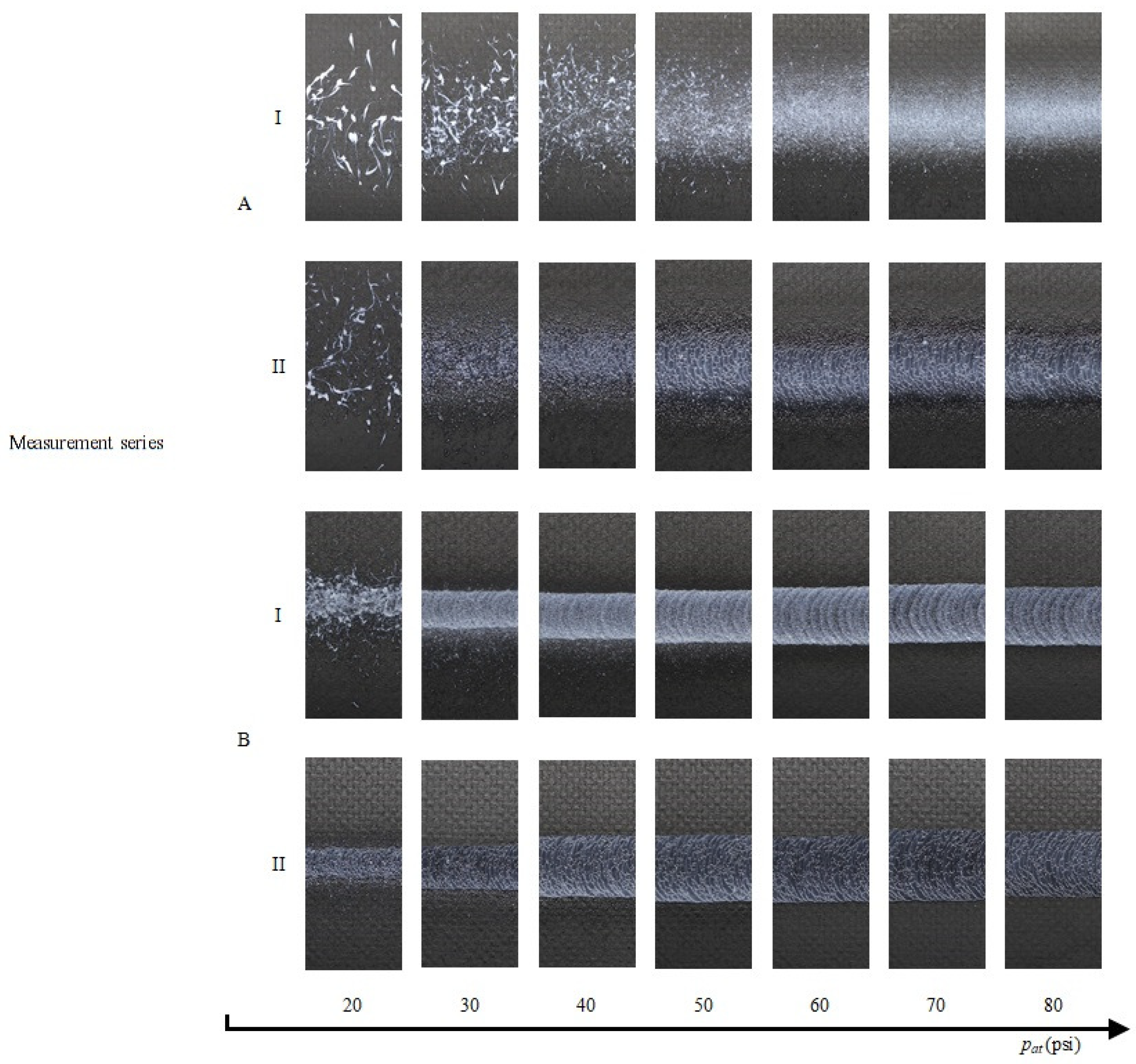
In Figure 3 and Figure 4, the widths of the sprayed grease for a nozzle of different construction and greases of different consistency are graphically compared. It can be seen that, at low atomization pressures, there are inhomogeneities in the structure of the sprayed layers. Its edge is not uniform. Sometimes, instead of a layer of material, drops of material of varying diameters are applied—the lower the atomization pressure, the larger the diameter of the drops applied to the substrate.
The images presented in Figure 3 and Figure 4 show droplets (systems AI, AII, and BI; pressure 20 psi), indicating the insufficient coverage of the material surface with lubricant, which can contribute to its wear. For system AI, droplet coverage of the surface was also observed at higher pressure values, up to around 50 psi. Surface coverage for system AII is acceptable at pressures from 30 psi, but only fully satisfactory at around 50 psi. Systems BI and BII are acceptable for pressures greater than 30 psi. Systems BI and BII have a narrower path compared to systems AI and AII.
After transforming the images in the Image-Pro Plus program, it is possible to evaluate the thickness of the lubricant layer applied to the base material. Of course, this is a simplified relationship between shades of gray vs. lubricant layer thickness. The color red indicates areas where a thicker lubricant layer has appeared. It is particularly visible in the case of system AI, which is characterized by the formation of droplets or a thicker layer along the axis of the nozzle.
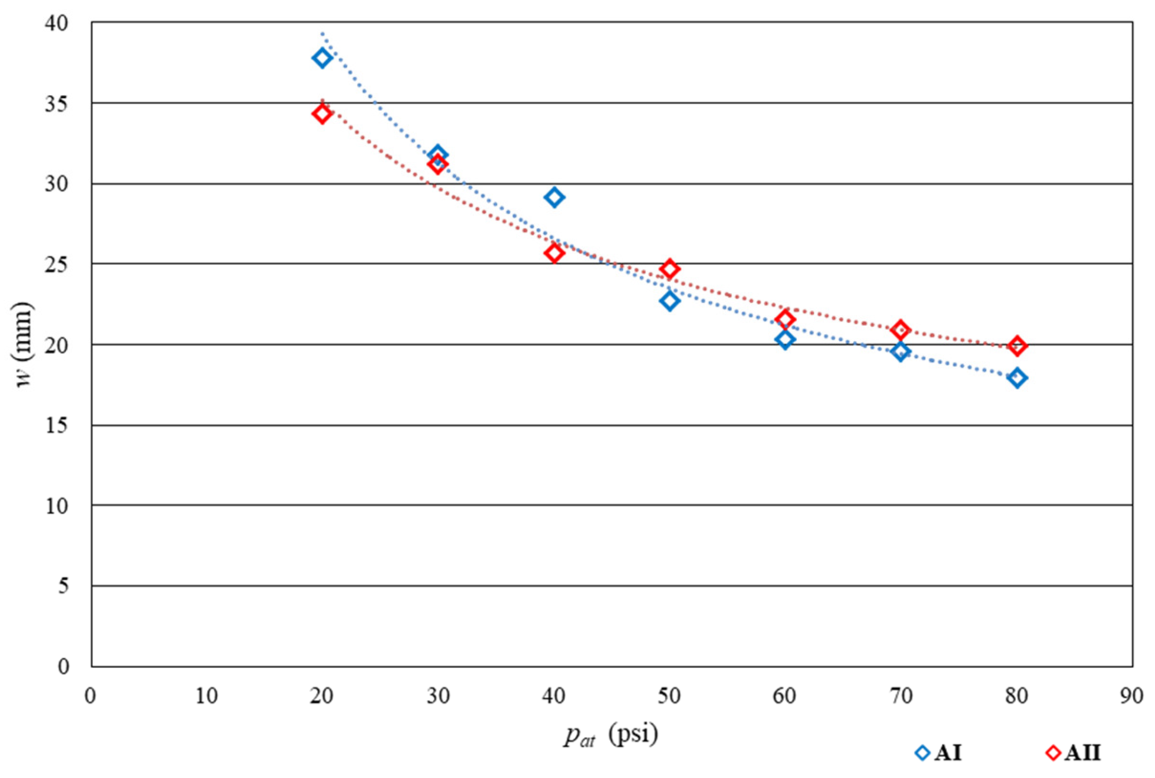
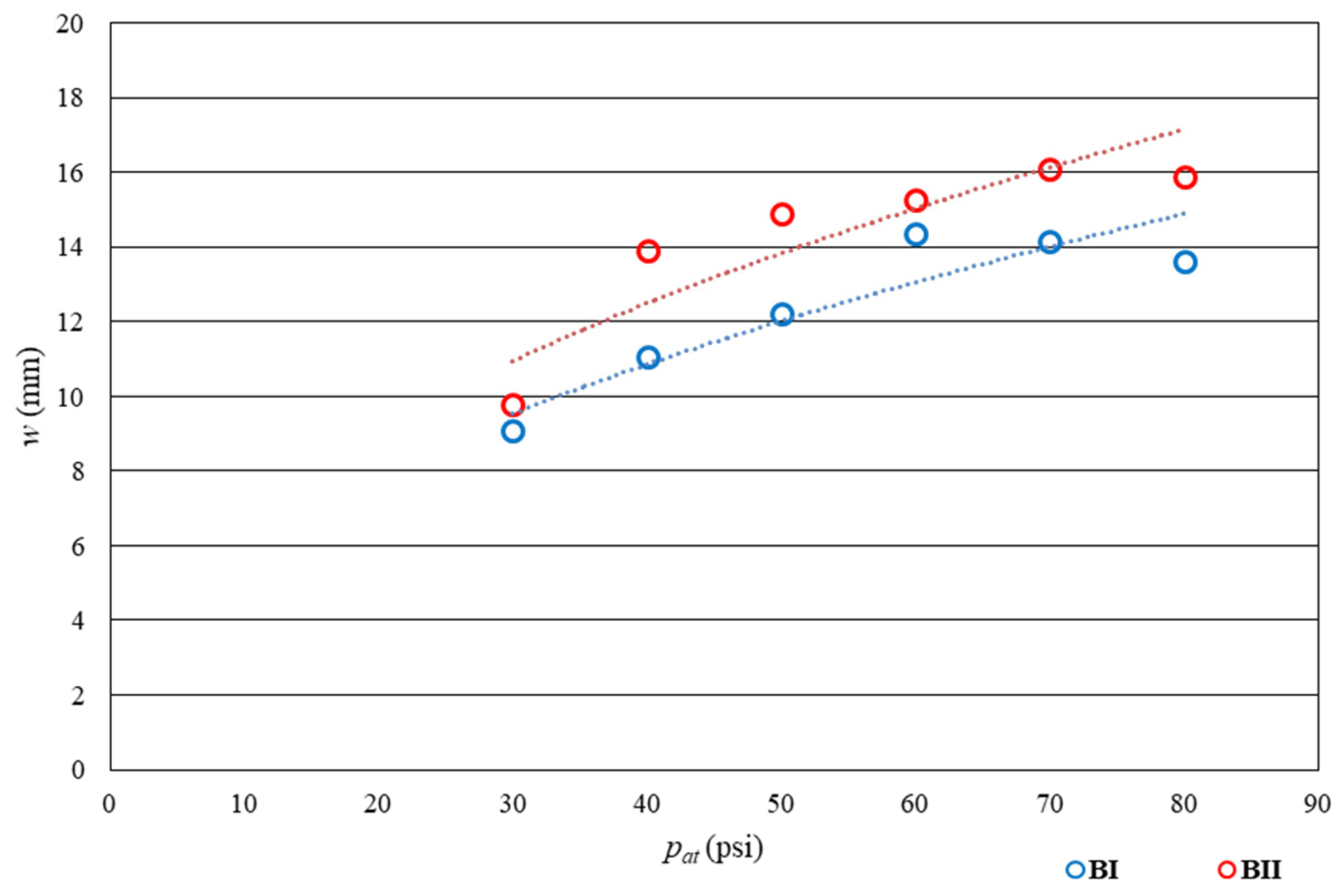
In Figure 5 and Figure 6, the relationship between the obtained width of the spray path and the variable atomization pressure is shown. In Figure 5, the relationship of the width of the spray path vs. pressure for nozzle Nordson EFD 7856F-46SS 0.046″ with a flat spray is shown, and in Figure 6, the relationship for nozzle Nordson EFD 7856-46SS 0.046″ with a full cone spray is shown. The letters A and B indicate the type of nozzle used. Roman numerals indicate the type of lubricant used: I is lubricant No. I classified in the 2nd class according to NLGI, and II is lubricant No. II classified in the 0th class according to NLGI.
Analyzing Figure 5 and Figure 6, it is evident that as the atomization pressure increases, the width of the spray path changes. In the case of using a flat spray nozzle, the width decreases with increasing pressure, while in the case of a round spray nozzle, the value increases. Comparing all measurement series (Figure 5 and Figure 6), it can be clearly stated that larger values of the width of the sprayed lubricant were obtained when using a flat spray nozzle. Using the given values of atomization pressure, when using the two nozzles interchangeably, a spray width of 9 to 37 (mm) can be obtained. The most extreme results regarding the width of the material path were obtained when using lubricant No. I. Both lubricant No. I and lubricant No. II, despite being classified into different consistency classes according to NLGI, allowed for the creation of a lubricating layer with a varied width and in some cases with a similar value. However, every time the nozzle is replaced using a time-pressure valve, it is necessary to check whether the material dose is the same and is 7.5 (g/min).
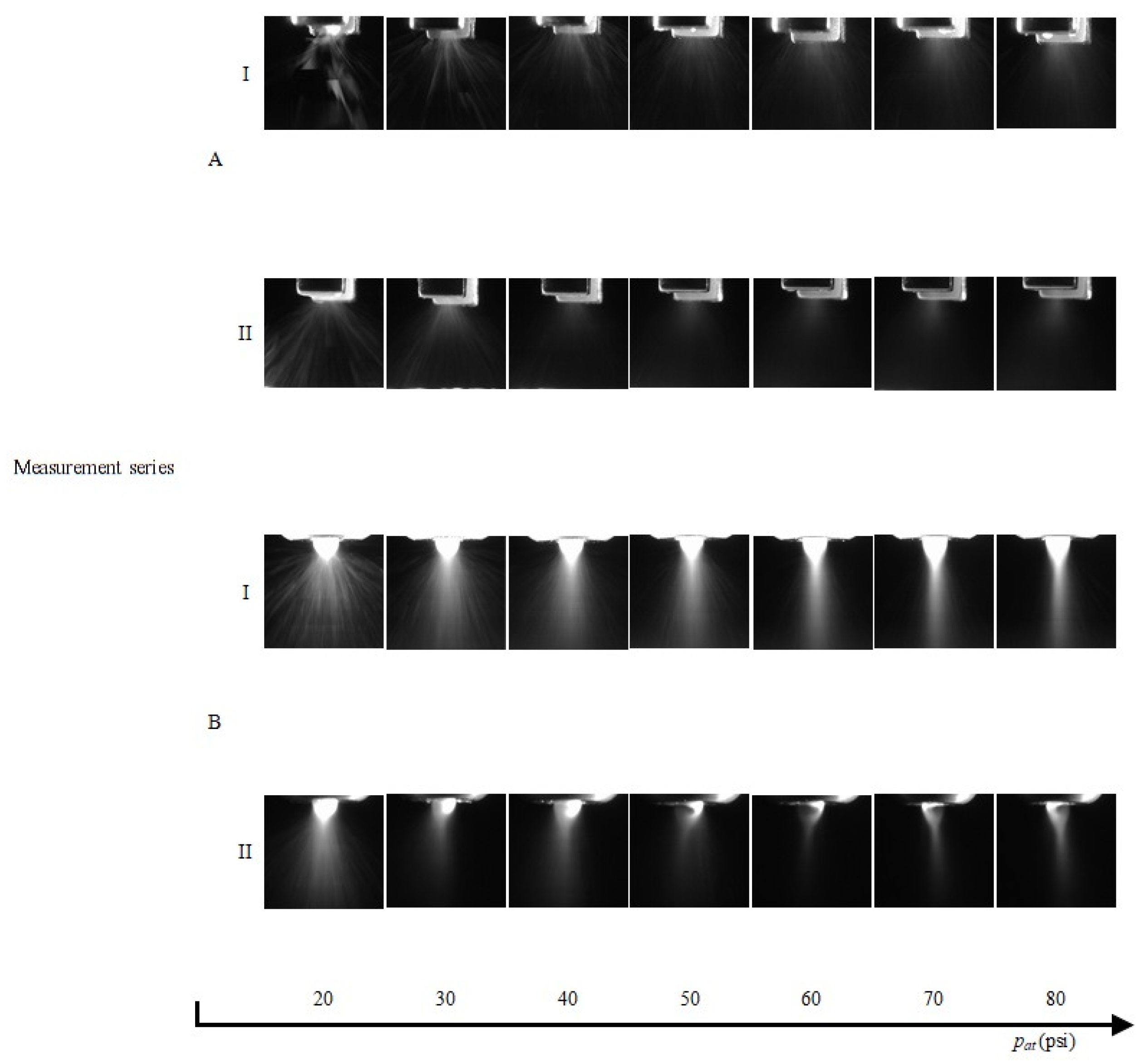
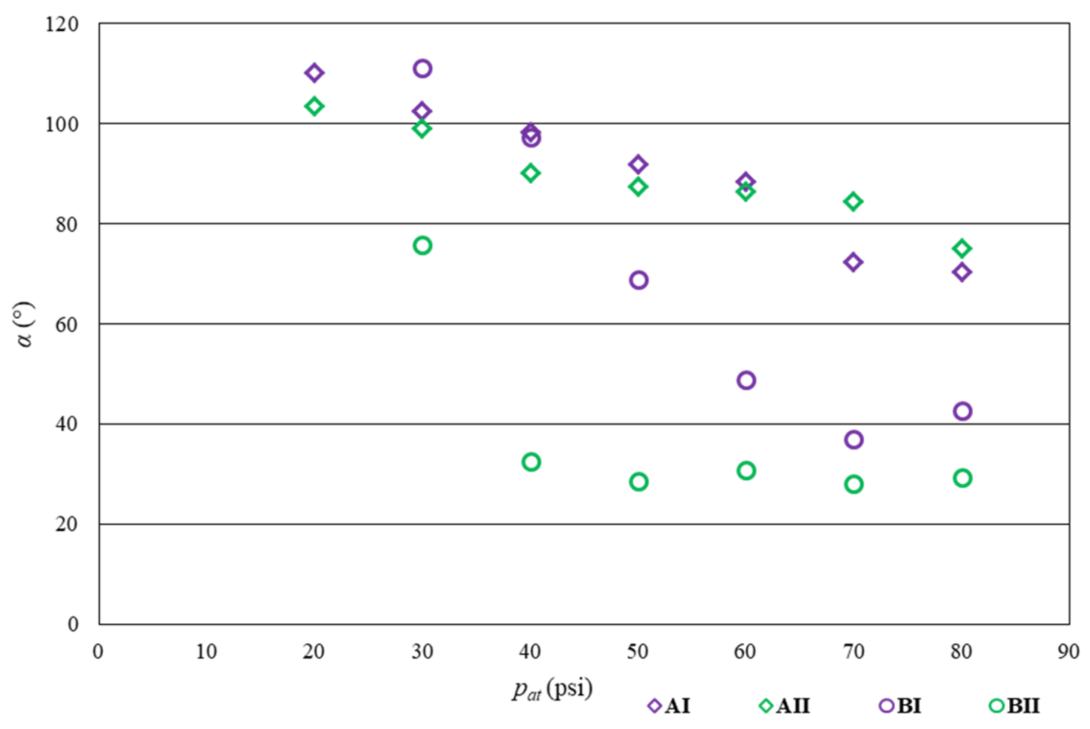
Figure 7 shows a graphical comparison of the spray angle (α) for the sprayed lubricant in the different measurement series. There is a visible downward trend for the value of the spray angle with increasing atomization pressure. In Figure 8, the changes in the spray angle depending on the atomization pressure are presented. The analysis of the obtained experimental data showed that for systems AI and AII, the obtained spray angle values decreased from 100–120° at a pressure of 20–40 psi to around 70° at a pressure of 80 psi. For system BI, the trend of decreasing spray angle values is similar, with the difference being that, at pressures >60 psi, the angle values are around 40°. For system BII, the spray angle values decrease much faster, as, at pressures of 30–40 psi, the observed spray angles are already around 30°, and further increasing pressure does not cause significant change. When spraying lubricants, this value showed a downward trend. This is due to, for example, the fact that at low atomization pressures, there was a significant dusting of the material. As a result, the analyzed photograph showed a fairly wide spray angle. With the increase of the atomization pressure, the spray disappeared, so that at such pressure values, lower and lower values of the spray angle can be noted. However, it should be remembered that the measurement error at the spray angle can be up to ±4°. It can be concluded that higher values of the spray angle could be recorded using lubricant No. I and for a fan-flat atomizer. However, these values may be slightly overestimated due to the previously mentioned dust spray, especially at the initial points.
The results of the experimental tests and analysis revealed that when atomization pressures are low, the edge of the spray is uneven and there is a significant amount of dusting. However, as the atomization pressures increase, the edge of the spray becomes more defined and there is no dusting present. The material layer appears to be more uniform, but at pressures above 70 psi, the spray takes on a wave-like appearance. Additionally, during dusting, inhomogeneities in the material layer are visible in the form of drops of varying volumes and shapes. When using round nozzles, the material is more uniform and the edge of the spray is clearer. On the other hand, when using a flat nozzle, the uniformity of the material and the edge are not as good as with a round nozzle. However, a flat nozzle allows for a wider width of the material path compared to a round nozzle. The width of the material path decreases with a flat nozzle, but increases with a round nozzle. Additionally, it was also observed that the spray angle decreases as the atomization pressure increases.
This study aimed to assess a test method that would enable an objective qualitative analysis of the interactions between grease applied with spray nozzles and the working surface. The conducted research allowed us to propose a method for the evaluation of sprayed lubricant coatings. The atomization of grease was the initial stage. Afterwards, the coatings were photographed, and the obtained image was subjected to computer processing using Image-Pro Plus in accordance with the formulated algorithm. The study used test grease samples, which were enriched with commercial additives. The study results showed a correlation between the pressure and nozzle type and the size of the surface area covered with the tested product.

4. Conclusions

In summary, this study aimed to analyze the process of applying technical coatings made of plastic greases with different consistencies based on the NLGI classification. The research was conducted using a time-pressure valve with compatible nozzles, which had the same outlet hole diameter but different constructions. The experimental results revealed that low atomization pressures led to an uneven edge and excessive dusting, whereas high atomization pressures resulted in a clear spray edge and no dusting. However, at pressures above 70 psi, the spray became visible in the form of a wave. During dusting, the layer of material displayed inhomogeneities in the form of drops with varying volumes and shapes. Round nozzles produced a higher uniformity of the material and a clear edge compared to flat nozzles, which exhibited a lower uniformity of the material and edge. Using flat nozzles allowed for a wider material path width than using round nozzles, and the width of the material path decreased with a flat nozzle but increased with a round nozzle. Moreover, the spray angle decreased with increasing atomization pressure. These findings can serve as a foundation for further research in analyzing the application process of non-Newtonian fluid coatings. The described methods can be further developed to enhance the understanding of this process. The obtained results indicate the possibility of applying the computer image analysis algorithm to the comparative evaluation of the degree of greases on surfaces.

Author Contributions

Conceptualization: M.O., S.W. and K.W.; investigations: M.O., K.W., M.M., A.K., S.W. and Z.B.; writing: M.O., K.W., Z.B., M.M., A.K. and S.W. All authors have read and agreed to the published version of the manuscript.

Funding

The research was financed within the project SBAD by the Polish Ministry of Education and Science.

Institutional Review Board Statement

Not applicable.

Informed Consent Statement

Not applicable.

Data Availability Statement

The data presented in this study are available on request from the corresponding author.

Conflicts of Interest

The authors declare no conflict of interest.

References

  1. Gateman, S.A.; Alidokht, S.A.; Mena-Morcillo, E.; Schulz, R.; Chromik, R.R.; Kietzig, A.-M.; Parkin, I.P.; Mauzeroll, J. Wear resistant solid lubricating coatings via compression molding and thermal spraying technologies. Surf. Coat. Technol. 2021, 426, 127790. [Google Scholar] [CrossRef]
  2. Lee, S.W.; Hong, J.W.; Wye, M.Y.; Kim, J.H.; Kang, H.J.; Lee, Y.S. Surface modification and adhesion improvement of PTFE film by ion beam irradiation. Nucl. Instrum. Methods Phys. Res. Sect. B Beam Interact. Mater. Atoms. 2004, 219–220, 963–967. [Google Scholar] [CrossRef]
  3. Tie, L.; Li, J.; Liu, M.; Guo, Z.; Liang, Y.; Liu, W. Facile Fabrication of Superhydrophobic and Underwater Superoleophobic Coatings. ACS Appl. Nano Mater. 2018, 1, 4894–4899. [Google Scholar] [CrossRef]
  4. Wang, Y.; Yan, F. Tribological properties of transfer films of PTFE-based composites. Wear 2006, 261, 1359–1366. [Google Scholar] [CrossRef]
  5. Burmistrov, D.E.; Serov, D.A.; Simakin, A.V.; Baimler, I.V.; Uvarov, O.V.; Gudkov, S.V. A Polytetrafluoroethylene (PTFE) and Nano-Al2O3 Based Composite Coating with a Bacteriostatic Effect against E. coli and Low Cytotoxicity. Polymers 2022, 14, 4764. [Google Scholar] [CrossRef] [PubMed]
  6. Maghsoudi, K.; Momen, G.; Jafari, R.; Farzaneh, M. Direct replication of micro-nanostructures in the fabrication of superhydrophobic silicone rubber surfaces by compression molding. Appl. Surf. Sci. 2018, 458, 619–628. [Google Scholar] [CrossRef]
  7. Demian, C.; Liao, H.; Lachat, R.; Costil, S. Investigation of surface properties and mechanical and tribological behaviors of polyimide based composite coatings. Surf. Coat. Technol. 2013, 235, 603–610. [Google Scholar] [CrossRef]
  8. Xu, B.; Zhu, Z.; Ma, S.; Zhang, W.; Liu, W. Sliding wear behavior of Fe–Al and Fe–Al/WC coatings prepared by high velocity arc spraying. Wear 2004, 257, 1089–1095. [Google Scholar] [CrossRef]
  9. Guilemany, J.; Dosta, S.; Miguel, J. The enhancement of the properties of WC-Co HVOF coatings through the use of nanostructured and microstructured feedstock powders. Surf. Coat. Technol. 2006, 201, 1180–1190. [Google Scholar] [CrossRef]
  10. Chen, X.; Gong, Y.; Suo, X.; Huang, J.; Liu, Y.; Li, H. Construction of mechanically durable superhydrophobic surfaces by thermal spray deposition and further surface modification. Appl. Surf. Sci. 2015, 356, 639–644. [Google Scholar] [CrossRef]
  11. Kałdońki, T.J.; Gryglewicz, Ł.; Stańczyk, M.; Kałdoński, T. Investigations on lubricity and surface properties of selected perfluoropolyether oils. J. KONES Powertrain Transp. 2011, 18, 199–212. [Google Scholar]
  12. Perfluoropolyethers a Unique Source for High Performance Pfpe Lubricants. Available online: www.solvaysolexis.com/static/wma/pdf/6/9/9/2/Perfluoropolyethers.pdf (accessed on 25 April 2022).
  13. Fomblin PFPE Lubricants. Solvay Solexis, Manufacturer’s. Available online: www.solvaysolexis.com/static/wma/pdf/1/1/7/3/0/fom_lube.pdf (accessed on 10 January 2023).
  14. Tyndall, G.; Leezenberg, P.; Waltman, R.; Castenada, J. Interfacial interactions of perfluoropolyether lubricants with magnetic recording media. Tribol. Lett. 1998, 4, 103–108. [Google Scholar] [CrossRef]
  15. Grechin, A.; Schott, V.; Kling, R. PFPE-Greases: Modern Trends and Perspectives. Conference ELGI AGM, London. April 2018, pp. 1–11. Available online: https://www.researchgate.net/publication/324830711_PFPE-Greases_modern_trends_and_perspectives (accessed on 10 January 2023).
  16. Von Krusenstierna, A. Grease-Oil Compatibility in Tribological Applications—Supergrease. Master’s Thesis, Faculty of Engineering, Lund University, Lund, Sweden, 2016. [Google Scholar]
  17. Fluid Solutions, Inc. Available online: https://fluidsolutions.com.ph (accessed on 5 January 2023).
  18. Caporiccio, G.; Soldini, S.; Strepparola, E. Process for Preparng Lubricating Greases Based on Polytetrafluoroethylene and Perfluoropolyethers. US Patent No 4472290, 18 September 1984. [Google Scholar]
  19. Krawiec, S. The Compositions of Plastic and Solid Lubricants in the Friction Process of Steel Machine Components; Publishing House of Wrocław University of Technology: Wroclaw, Poland, 2011. [Google Scholar]
  20. Scharf, T.W.; Prasad, S.V. Solid lubricants: A review. J. Mater. Sci. 2013, 48, 511–531. [Google Scholar] [CrossRef]
  21. Czarny, R. Plastic Lubricants; WNT Publishers, reprinted by PWN Scientific Publishers: Warsaw, Poland, 2018. [Google Scholar]
  22. Kozdrach, R. The effect of the type of dispersing phase on the tribological properties of plastic lubricants. Tribology 2012, 6, 85–97. [Google Scholar]
  23. Gow, G. Lubricating grease. In Chemistry and Technology of Lubricants; Mortier, R.M., Orszulik, S.T., Eds.; Springer: Boston, MA, USA, 1992. [Google Scholar] [CrossRef]
  24. Drabik, J. Impact of additives on tribological characteristics of plastic lubricants. Tribologia 2015, 5, 17–28. [Google Scholar]
  25. Parfenov, A.S.; Berezina, E.V.; Smirnova, A.I.; Gvozdev, A.A.; Shilov, M.A.; Dyachkova, T.; Rozhkova, N.N.; Savilov, S.V.; Usol’Tseva, N.V. Tribological Properties of Plastic Lubricants in Compositions with Various Carbon Nanostructures. J. Frict. Wear 2019, 40, 453–460. [Google Scholar] [CrossRef]
  26. Pawelec, E.; Siwiec, E. The effect of lubricant additives on selected rheological properties. Tribology 2012, 6, 129–138. [Google Scholar]
  27. Kamel, B.M.; El-Kashif, E.; Hoziefa, W.; Shiba, M.S.; Elshalakany, A.B. The effect of MWCNTs/GNs hybrid addition on the tribological and rheological properties of lubricating engine oil. J. Dispers. Sci. Technol. 2021, 42, 1811–1819. [Google Scholar] [CrossRef]
  28. Ukomski, A. Oils, lubricants, tribology. Des. Eng. Constr. 2020, 4, 14–21. [Google Scholar]
  29. Bajer, J. Characteristic properties of low temperature resistant plastic grease. Tribology 2006, 5, 97–110. [Google Scholar]
  30. Tiwari, S.; Christy, J.V. Tribological Analysis of Thermal Spray Coatings of Ni and Al2O3 with Dispersion of Solid Lubricants in Erosive Wear Modes. Procedia Technol. 2016, 23, 150–155. [Google Scholar] [CrossRef] [Green Version]
  31. Ganvir, A.; Jahagirdar, A.R.; Mulone, A.; Örnfeldt, L.; Björklund, S.; Klement, U.; Joshi, S. Novel utilization of liquid feedstock in high velocity air fuel (HVAF) spraying to deposit solid lubricant reinforced wear resistant coatings. J. Mater. Process. Technol. 2021, 295, 117203. [Google Scholar] [CrossRef]
  32. Accurately Spray Coatings and Lubricants Using Spray Technology. Available online: https://engineeringnews.co.nz/2017/08/23/accurately-spray-coatings-and-lubricants-using-spray-technology/ (accessed on 20 February 2023).
  33. Grützmacher, P.G.; Schranz, M.; Hsu, C.-J.; Bernardi, J.; Steiger-Thirsfeld, A.; Hensgen, L.; Ripoll, M.R.; Gachot, C. Solid lubricity of WS2 and Bi2S3 coatings deposited by plasma spraying and air spraying. Surf. Coat. Technol. 2022, 446, 128772. [Google Scholar] [CrossRef]
  34. Nordson EFD. Game Changing Dispensing Solutions. In Engineered Fluid Dispensing, 9th ed.; Nordson EFD: Vestlejk, OH, USA, 2019. [Google Scholar]
  35. Technical Data Sheet for PFPE Lubricants. 2022.
  36. Molenda, J.; Wójcicki, T.; Pawelec, E. Application of a computer image analysis for quantitative description of adhesive interactions between grease and steel surface. Nafta Gaz 2011, 67, 361–366. [Google Scholar]
Figure 1. Scheme of the measuring station [34].
Applsci 13 02983 g001
Figure 2. Shape of the obtained sprays [34]: (a) solid cone when using Nordson EFD 7856-46SS 0.046″ nozzle; (b) fan-flat when using Nordson EFD 7856F-46SS 0.046″ nozzle; (c) exemplary measurements of the spray angle.
Applsci 13 02983 g002
Figure 3. Graphical comparison of the width of the sprayed lubricant coatings (A) = nozzle with flat spray, (B) = nozzle with full cone spray, I = lubricant No I, II = lubricant No II.
Applsci 13 02983 g003
Figure 4. Graphical comparison of the width of the sprayed lubricant coatings in each of the measurement series after the analysis in the Image-Pro Plus program—the pseudo-color was used (A) = nozzle with flat spray, (B) = nozzle with full cone spray, I = lubricant No I, II = lubricant No II.
Applsci 13 02983 g004
Figure 5. The dependence of the width of the sprayed material path (w) vs. the atomization pressure (pat) for series AI and AII.
Applsci 13 02983 g005
Figure 6. The dependence of the width of the sprayed material path (w) vs. the atomization pressure (pat) for series BI and BII.
Applsci 13 02983 g006
Figure 7. Graphical comparison of spray angle of sprayed lubricant coatings (A) = nozzle with flat spray, (B) = nozzle with full cone spray, I = lubricant No I, II = lubricant No II.
Applsci 13 02983 g007
Figure 8. The dependence of the spray angle (α) vs. the atomization pressure (pat).
Applsci 13 02983 g008
Table 1. Classification of plastic lubricants according to their consistency (NLGI) [19].
NLGI Consistency Class
(DIN 51 818)
Penetration
According to PN/C-96-04095 (0.1 mm)
ConsistencyBasic Application
000440–480liquidMechanical transmissions, central lubrication systems
00395–435semi-liquid
0350–390semi-liquid
1305–345very softRolling and sliding bearings, central lubrication systems
2260–300soft
3215–255medium
4170–210thickOther uses; most commonly used as a sealant for fittings
5125–165very thick
680–120 (penetration in a resting state)hard
Table 2. The characteristics of lubricants used [35].
CharacteristicsLubricant No. 1Lubricant No. 2
Base oilPFPEPFPE
Viscosity of oil at 40 °C (mm2/s)88
ThickenerPTFEPTFE
Density (kg/dm3)1.931.93
Penetration × 0.1 mm265–295355–385
NLGI class20
Vapor pressure at 70° C (Torr)10−3<10−2
Operating temperature range (°C)−70–200−70–200
Table 3. The measurements series (A = nozzle with flat spray, B = nozzle with full cone spray).
DesignationNozzleLubricantTemperature of Air (°C)Humidity of Air (%)Pressure of Lubricant (psi)
AINordson EFD 7856F–46SS 0.046″No I20.938.640.0
AIINo II21.038.314.5
BINordson EFD 7856–46SS 0.046″No I20.833.915.05
BIINo II20.834.414.5
Disclaimer/Publisher’s Note: The statements, opinions and data contained in all publications are solely those of the individual author(s) and contributor(s) and not of MDPI and/or the editor(s). MDPI and/or the editor(s) disclaim responsibility for any injury to people or property resulting from any ideas, methods, instructions or products referred to in the content.