Abstract
In view of the current technical difficulties in the detection of unfavorable geological bodies in karst areas, this paper starts with the fine detection of a borehole wall, near-field of the borehole wall rock and far-field of the borehole wall rock, deeply excavates the correlation characteristics between multi-source borehole data, and proposes detection technology for unfavorable geological bodies in karst development areas based on multi-source borehole data. This is used to establish a multi-source data depth mining model. The correlation characteristics between multi-source data are clarified. The borehole multi-source heterogeneous detection technology is proposed to realize the organic fusion between the detection data of different scales, and effectively estimate the extension range of structural planes and cavities. The joint interpretation method of multi-source drilling data can effectively realize the three-dimensional visualization of unfavorable geological bodies in karst development areas. Through a case analysis, it is shown that this technology is a new and effective exploration method in the engineering geological exploration of karst development areas, and can provide more abundant and reliable exploration data for the fine exploration of geological bodies in the exploration area.
1. Introduction
With the extensive development of engineering, those in construction have realized the importance of karst more and more, and began to conduct comprehensive analysis and research. This includes comprehensive analysis and research on the formation environment, influencing factors, types, geological and geomorphological features of karst and have achieved good results which are widely used in engineering geology. Under the dissolution of surface water and groundwater, different types of karst landforms and forms appear in nature, which largely destroy the integrity of rocks, and also affect the stability of rocks. With the development of social economy, more engineering projects need to be established in karst areas, and geological exploration in karst areas is increasingly valued by construction units. In the actual exploration and detection process, different technical means should be adopted according to the actual situation to better serve the project construction. At the same time, the development degree of karst will affect the normal construction of water conservancy, railways, highways, bridges and other construction projects. As the scale of engineering buildings in karst areas continues to expand and the number continues to increase, how to improve the detection and exploration technology in karst areas is an important issue faced by exploration units [1,2,3,4]. Therefore, in order to improve the quality and effect of exploration, the exploration personnel should adopt scientific and reasonable methods according to the characteristics and nature of karst. In engineering construction, adverse geological bodies, such as karst caves, fracture zones and fault fracture zones, are often encountered. If the existence of adverse geological bodies and their water content cannot be detected in advance, serious potential safety hazards will be buried, which is very likely to cause casualties, construction delay and major economic losses.
At present, for the process of detecting adverse geological bodies in karst development areas, the traditional borehole survey is mainly used. This not only requires a heavy workload, long process time and high cost, but it is also a limited and backward technology. For some areas with complex geological conditions, it is often easy to have faults, broken zone karst, underground rivers and other areas with unfavorable geological structures; since the survey results are not ideal, it is difficult to reflect the actual geological conditions. The GPR method is a fast, nondestructive and high-resolution detection method, which is very sensitive to water-bearing bodies and is very suitable for the detection of adverse geological bodies. However, due to the limitation of the detection depth, the general geological radar is not suitable for detecting the deep stratum structure. In order to obtain the structural information of deep strata directly, it is often necessary to drill holes, but because of the “one-hole view”, it is very easy to miss the source of disasters. By placing the antenna into the existing borehole, the occurrence of adverse geological bodies within a certain range around the borehole can be obtained, which can effectively solve the problems of limited detection depth and one-hole view of ordinary GPR. However, the borehole radar technology is not directional, and it is difficult to survey the small-size adverse geological bodies around the borehole [5,6,7,8,9]. Therefore, how to use a small number of boreholes and new survey technologies to accurately describe the structural characteristics of these unfavorable geology, speed up the progress of engineering surveys, reduce the cost of engineering, reduce the harm of unfavorable geology on the project, and ensure the safety and stability of the foundation are the difficulties and hotspots of current engineering geological surveys. To sum up, these common problems are the lack of a fast, accurate and advanced comprehensive survey technology [10,11,12,13,14].
The borehole optical imaging technology can effectively observe and measure the structural characteristics of the rock mass inside the borehole. At the same time, it can also obtain the geometric parameter information such as the occurrence, gap width and spacing of the structural plane. The borehole radar technology can effectively identify the possible abnormal rock mass structures around the borehole, such as karst caves and fractures. The borehole directional acoustic scanning technology can effectively find and measure the structural characteristics of the rock mass near the borehole wall, and realize the three-dimensional visualization of the surrounding rock structure of the borehole. However, these three survey technologies have their own advantages and disadvantages. In order to better understand a key survey area, these three survey technologies are simultaneously applied to common survey boreholes to realize the visualization of the wall of the survey boreholes, the identification of the abnormal structure around the boreholes and the shape carving of the rock mass structure around the boreholes [15,16,17]. This paper starts with the fine detection of the borehole wall, including the near-field of borehole-surrounding rock and far-field of borehole-surrounding rock, and deeply excavates the correlation characteristics between multi-source borehole data. Then, is proposed a detection technology for unfavorable geological bodies in the karst development area that integrates the optical imaging technology of borehole, directional acoustic scanning technology of borehole and borehole radar technology. The realization of the joint interpretation and fusion of the three kinds of detection data has laid an important theoretical and methodological foundation for the fine detection technology of unfavorable geological bodies in karst development areas.
2. Borehole Multi-Source Data Acquisition Technology
2.1. Borehole Optical Imaging Technology
The borehole optical imaging technology can directly obtain the texture image information of the borehole wall, which is a direct observation technology. Borehole optical imaging technology is a kind of detection technology that places the panoramic camera probe inside the borehole to obtain the panoramic image of the borehole wall [18,19]. The light source of the probe in the borehole illuminates the camera area on the borehole wall. The panoramic camera simultaneously captures the panoramic image of the borehole and the compass azimuth image, and transmits the captured image to the video distributor located on the ground through a special cable. One cable enters the video recorder to record the whole process of detection, and the other cable enters the capture card in the computer for digitization. The measuring wheel on the winch measures the position of the probe in the borehole in real time, and places the depth value in the special port in the computer through the interface board. The probe is lowered in the borehole until the end of the whole detection process. Through continuous capture, the panoramic image of the borehole can be quickly restored to the plane expansion diagram and displayed in real time. The borehole camera image and the plane expansion diagram are shown in Figure 1. “W”, “N”, “E” and “S” in Figure 1 represent the west, north, east and south of the geography. The face represented by ABCD represents the intersection of joint and borehole. “A”, “B”, “C” and “D” represent several typical joint locations on the borehole. The blue and red lines in the figure have no special meaning, although they are convenient to explain the orientation correspondence of the borehole expansion image.
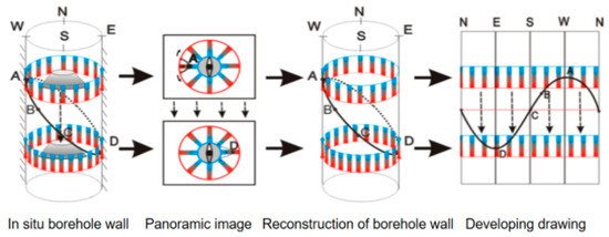
Figure 1.
Plane expansion diagram.
A borehole detection environment has the particularities of small space and small size of target body, so the conventional stereo image pair imaging method is not applicable in the borehole. Therefore, an in-hole stereo image pair acquisition method based on combined binocular panoramic imaging is proposed. The main technical points include the following: (1) Use of the upper and lower conic mirrors with different inclination angles to reflect the 360° image information of the borehole wall into the imaging component. (2) An imaging component is set directly above the biconical mirror to collect the panoramic images of the borehole wall from two different observation angles in real time, so that a single imaging component can be obtained from the panoramic stereo image of the hole. (3) A precondition for the image formed by the reflection of the biconical mirror to be an effective image pair image is that the image contains overlapping areas. Therefore, the parameters of the conic mirror and imaging components are designed accordingly to enable it to obtain the best stereoscopic image pair image. Imaging principle of biconical mirror stereo image pair is shown in Figure 2.
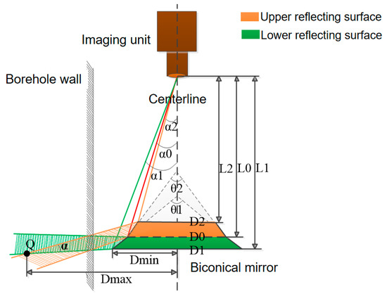
Figure 2.
Imaging principle of biconical mirror stereo image pair.
The core problem of the panoramic image pair image solution is to obtain the borehole wall stereo image, which mainly includes two aspects: (1) image pair image registration and (2) the distance from any point on the borehole wall to the imaging center axis. For image-to-image registration, the method of automatic search and recognition of registration points is adopted. The specific location is determined as follows: take any point P in the circular band between C1 and C0 or C0 and C2, and its azimuth line OP is the line between the point and the center of the circle. Then, along the OP, search for the same point P’, that is, the registration point, in another ring (that is, the ring between C0 and C2 or C1 and C0), and calculate the image coordinates of the registration point P’. Schematic diagram of panoramic image solution is shown in Figure 3.
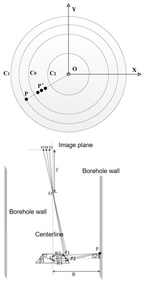
Figure 3.
Schematic diagram of panoramic image solution.
To solve the distance from any point on the borehole wall to the imaging center axis, analyze the imaging path of the borehole wall in the form of biconical mirror, define the basic imaging parameters and establish the solution formula, specifically
where is the distance from point P to the imaging center axis and is the elevation difference between point P and the bus circle. is the horizontal distance between the midpoint of the bevel of the conical mirror and the central axis. is the horizontal distance between the reflection point F2 and the central axis of the conical mirror. is the horizontal distance between the reflection point F1 and the central axis of the conical mirror. α1 is the included angle between the line segment F1r2 and the central axis. α2 is the included angle between the line segment F2r1 and the central axis. β1 is the included angle at the bottom of the conical mirror. β2 is the included angle at the top of the conical mirror. h is the vertical distance between the reflection point F1 and the reflection point F2.
2.2. Borehole Directional Acoustic Scanning Technology
The borehole directional acoustic scanning technology mainly uses the reflection characteristics of the acoustic pulse to reflect the structural characteristics of the rock mass inside the borehole-surrounding rock, and realizes the acoustic scanning of the borehole-surrounding rock structure by using the technical method of combining the directional acoustic probe, rotating the device and positioning the device [20,21]. On the horizontal section at a certain depth of the borehole, the directional acoustic transducer vertically transmits a series of acoustic signals to the borehole wall, receives the reflection signals of the rock mass inside the rock wall, uploads the signals to the ground computer and stores them. Then, driven by the rotary device, the directional acoustic transducer rotates according to a fixed angle, and the directional acoustic transducer vertically transmits a series of acoustic signals to the borehole wall. It also receives the reflection signal of the rock mass inside the rock wall, uploads the signal to the ground computer and stores it. This process is repeated to achieve complete scanning of the section. At the same time, it records the azimuth information of each wave in real time through the positioning device, including the depth and azimuth information of the directional acoustic transducer. The scanning diagram is shown in Figure 4.
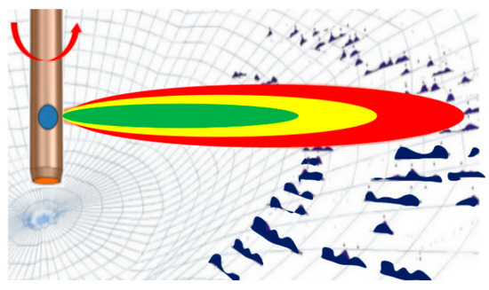
Figure 4.
Scanning diagram of directional acoustic probe.
In order to more intuitively display the abnormal regional characteristics of the borehole-surrounding rock, it is necessary to reconstruct the image of the borehole-surrounding rock. In the composite section diagram of fixed depth, a circular scanning matrix diagram is established, as shown in Figure 5a. The innermost circle of the circular diagram represents the acoustic reflection signal of the borehole surface, and the outermost circle represents the maximum scanning value of the directional acoustic wave, that is, the maximum detection range around the surrounding rock. Its size is determined by the performance of the equipment and the acoustic propagation characteristics of the rock. Different detection environments usually differ in size. The single scanning length is twice the maximum detection range, and its single scanning length is the product of sampling points, sampling interval time and rock acoustic propagation speed. Other circles in the interior are arranged from inside to outside according to time, and their size is the amplitude of the acoustic echo signal.
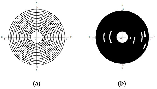
Figure 5.
Schematic diagram of surrounding rock structure scanning. (a) Circular scanning matrix. (b) Borehole-surrounding rock section.
This process is determined by the number of sampling points. Thus, if there are n sampling points in a complete scanning wave, the sector area formed by the innermost circle and the second inner circle display the information represented by the first sampling point of the scanning signal, and the sector area formed by the second outermost circle and the outermost circle display the information represented by the nth sampling point of the scanning signal. If the number of scanning lines of each section is m, then the sector area is used to represent the surrounding rock structure information of the j-th sampling point on the i-th scanning line at the depth h, where 1 ≤ i ≤ m, 1 ≤ j ≤ n, the included angle of the span of sector area is 2π/m, and the span width of sector area is Δt, where ΔT is the sampling interval of the signal.
Let represent the i-th scan signal of the directional acoustic transducer at the depth of h, including the transmit signal and the echo signal, and discretize the signal into , where the first point of is the trigger point of the transmit signal. Then take the absolute value of the signal to ensure that the amplitude of the signal is positive. Normalize the signal in [0, 1] interval to obtain the following :
In order to highlight the characteristic area, is obtained by inverting the signal. If the value of the signal is close to 1, it means that there is no reflected echo at this location and the surrounding rock structure is normal. If the value of signal is close to 0, it indicates that there is an abnormal echo at this location, and the surrounding rock structure may be abnormal. The expression of is as follows:
After completing the above signal processing, fill the value of signal into sector in turn, and the corresponding relationship is , as shown in Figure 5b.
After the section mapping at depth h is completed, multiple section maps of different depths are generated in the same way, and then the three-dimensional structure map of the borehole-surrounding rock can be formed by fault interpolation fitting. In order to make the image clear and beautiful, the generated image can be gray mapped according to the size of the information value of the sector area. Through image processing, the contour information of the internal defects in the surrounding rock of the borehole can be extracted.
2.3. Borehole Radar Technology
Borehole radar technology can effectively detect the rock mass structure information around the borehole, and is an effective technical method for the detection of unfavorable surrounding rock geological bodies [22,23,24,25,26]. Borehole radar technology is a technology used to detect the rock mass structure around the borehole by determining the distribution of broad-spectrum electromagnetism in the underground medium. It can penetrate a certain distance in the geotechnical medium, and the frequency used is usually 50~250 MHz. The borehole radar technology uses one antenna to transmit high-frequency broadband electromagnetic waves, and the other antenna to receive the transmitted waves from the underground rock and soil media. Because the propagation of the radar wave is affected by the electromagnetic properties and geometric shape of the rock and soil, the strength and waveform of the electromagnetic wave at the receiving end will change accordingly. According to this, the structural characteristics of underground rock and soil media can be inferred from the two-way travel time, amplitude and waveform data of the electromagnetic wave at the receiving end. The detection schematic diagram is shown in Figure 6.

Figure 6.
Schematic diagram of borehole radar detection.
The strength of the reflected signal of the electromagnetic pulse is related to the reflection coefficient of the interface and the absorption degree of the wave penetrating the medium. Generally, if the electromagnetic parameters of the medium vary greatly, the reflection coefficient is large, and therefore the energy of the reflected wave is also large. This is the prerequisite for the detection of borehole radar. The relationship formula is as follows:
Among them, PT and PR are the transmitting and receiving power of borehole radar, respectively. G is antenna gain. R, S and H are the reflectivity, scattering surface section and depth of the underground target, respectively. α is the attenuation rate of rock and soil. L is the scattering loss of radar wave from transmission to reception. λ0 is the wavelength of radar wave in the medium.
The basic principle of borehole radar is similar to that of ground radar. Generally, it uses a common transceiver antenna. The antenna moves along the direction of the borehole and transmits broadband high-frequency pulse to the surroundings of the borehole. It can penetrate a certain distance in the rock and soil and transmit and obtain signals through the transceiver antenna. The probe is connected with the ground control unit through optical fiber for data acquisition and signal triggering. There are three modes for borehole radar measurement, namely single-hole reflection mode, cross-hole mode and VRP mode. Because the probe is located underground, the borehole radar can detect deeper geological targets than the conventional geological radar. The radial detection radius depends on the physical properties of the rock, and can sometimes reach hundreds of meters. Borehole radar is widely used in engineering geological surveys and environment-related fields due to its special capabilities. Borehole radar, as a geophysical exploration method, is based on radar wave propagation through the underground medium. It can penetrate a certain distance in rock or soil, and the frequency is usually 10–1000 MHz. The propagation of the radar wave depends on the dielectric constant ε (=εrε0), permeability μ (=μrμ0), conductivity σ and angular frequency w (=2πf). With regard to parameter Q = wε/σ, it determines whether a certain medium supports the propagation of radar waves. If for a certain medium Q >> 1, the energy of electromagnetic wave mainly propagates in the form of wave. If Q << 1, it is mainly spread in the form of diffusion. The Q value is a measure of the number of wavelengths an electromagnetic wave can propagate for in the medium when the radar wave attenuates a certain amount. When Q >> 1, velocity v and attenuation coefficient α have the following relationship:
where Z0 (=377 Ω) is the free space wave impedance. Parameter δ = α−1 is called skin depth, which determines the propagation distance when the plane wave amplitude decreases to e−1. Some calculations also use it as the detection depth of radar.
3. Detection Technology of Adverse Geological Bodies
3.1. Borehole Multi-Source Heterogeneous Detection Technology
Due to the ever-changing geological conditions in karst development areas and the multiplicity of interpretation tasks, the combination of multiple detection methods is often needed to solve practical problems in practical projects. The so-called dynamic detection technology is a kind of detection technology that adjusts the layout and detection scheme of the survey points in real time. It works according to the established operation process, the detection task and the geological conditions of the site, so as to know whether there are any adverse geological bodies that may cause safety hazards to the project in the area of concern, thus achieving high efficiency and economy. It first conducts a comprehensive detection and on-site real-time analysis of a single hole, then judges whether there are adverse geological phenomena and whether it can meet the engineering safety requirements. This guides it whether or not to add new boreholes until it meets the requirements of the detection task, so as to realize the dynamic adjustment of the detection scheme.
Because the antenna of the borehole radar can receive a scattered echo from the abnormal body around the borehole in all directions, and the three-dimensional information is stored in the form of a two-dimensional time series during data acquisition, the size and depth of the abnormal body from the borehole axis can only be analyzed from the radar data of a single hole. Consequently, the azimuth information of the abnormal body cannot be determined. The data of borehole camera and borehole acoustic scanning can only identify the geological conditions of the borehole wall and its surroundings, including the trend and inclination of the fracture joint surface, and the distribution of the cavity area and karst area around the borehole wall. In order to quantitatively describe the distribution of abnormal geological bodies around the borehole, joint analysis of porous data is required. In order to determine whether the site is karst, with cavities and other adverse geological bodies in a certain area, dynamic detection technology is an economical and efficient method.
As shown in Figure 7, first select a place near the area of interest to make the first borehole A, and carry out optical imaging, borehole radar and borehole directional acoustic scanning according to the operation process of dynamic detection technology to predict whether there is any adverse geological body that may cause safety hazards to the project in the site. If not, there is no need to increase the borehole work. If it is found that there may be adverse geological bodies in the site, but the location is unknown, It is necessary to increase the borehole and survey work. The hole detected in borehole A may be either in the site area of concern (e.g., E) or outside the site area (e.g., F), so it is necessary to add a borehole B. If the detected hole is far beyond the scope of the site area from borehole B, it means that the borehole measured in borehole A is not in the site area, and the test work of the next borehole does not need to be added; otherwise, another borehole C needs to be added. At this time, the size and location of the abnormal body in the borehole can be estimated through the optical imaging of the borehole, borehole radar and the borehole directional acoustic scanning data of all three boreholes, and its impact on the project can be evaluated, so as to carry out the reinforcement measures for the subsequent works.
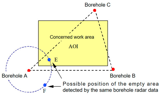
Figure 7.
Schematic diagram of dynamic survey project area.
3.2. Borehole Multi-Source Data Fusion Analysis Method
3.2.1. Analysis of Extension Range of Structural Plane
After acquiring accurate borehole optical imaging, borehole radar and borehole directional acoustic scanning data, the structural plane inclination, inclination and ductility steps are as follows:
Acquire the digital borehole wall image, analyze the sine curve of the structural plane intersected with the borehole, and calculate the inclination of the structural plane intersected with the borehole.
The borehole radar time profile is mapped, and the depth correction is carried out to find the radar profile image corresponding to the structural plane.
Analyze the radar profile image, if the echo curve is the upper and lower wings of regular open scissors, use the relationship (9) and relationship (10) to estimate the wave velocity of rock and soil near the structural plane νi and dielectric constant εr.
The approximate extension area of the structural plane is determined through the radar time profile of the structural plane. For the problem of the extension area of the structural plane, it is necessary to distinguish the types of radar time profile of the structural plane, including the radar time profile without pinch out and the radar time profile with pinch out. In the radar time profile with a pinch out structural plane, in addition to the reflected signal of the structural plane, sometimes the scattered signal at the tip of the structural plane can also be observed. However, in either case, an echo attenuation point or pinch out scattering point can be found as the minimum estimate of the extension of the structural plane; that is, the structural plane extends at least to this point, and the two-way travel time of the echo at this point is recorded as tnip.
In order to determine the actual position of the point in the radar time profile, it is also necessary to deduce the migration formula. Set the structural plane inclination as θ. The antenna distance TR in the borehole is d, and TE is h. Assume that the unknown CE length is s and the reflection angle is φ, then the radar echo propagation distance l is as follows:
Among
Since h >> d, it is generally considered that l1 ≈ l2, so the position coordinates (x, y) of the radar wave at the reflection point of the structural surface can be obtained as
Among
The actual position of any echo point in the radar time profile can be determined by relationship (16) and relationship (17). Therefore, when the measured two-way travel time of the echo at the echo attenuation point or the pinch out scattering point is t = tnip, the approximate extension range of the structural plane is also determined by calculating the actual position of the point.
Based on the above calculation results, the occurrence and extension of a structural plane can be obtained. As shown in Figure 8, the occurrence of structural plane and the approximate extension area can be obtained.
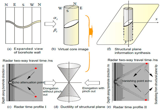
Figure 8.
Schematic diagram of dip angle and ductility of structural plane.
3.2.2. Analysis of Cavity Extension Range
Because of the hyperbolic radar image generated by the hollow target, the wave velocity can be determined by the hyperbolic shape of the echo. Edge detection and curve fitting are the simplest image processing methods. As shown in Figure 9, the size and location of the hole can be roughly estimated by using the echo curve of the hole target. The steps are as follows:
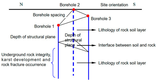
Figure 9.
Three boreholes position and data fusion diagram.
① Pre-processing, edge contour extraction and low-pass filtering of radar profile image.
② The radar wave velocity and dielectric constant of the target area are estimated using the method mentioned above.
③ The vertex of the hyperbola (t0, y0) is estimated in the echo curve of the hollow target.
④ Since the target echo curve points should meet the relationship (18), the point set (ti, yi) can be brought in to calculate the radius of the empty target, namely,
Due to the large amount of interference and noise in the target echo, the curve may appear discontinuous or have an irregular hyperbolic shape. Therefore, a series of radius values can be calculated for the point set (ti, yi). At this time, the average value of these calculated results is not taken as the radius of the actual target, but the interval with the densest radius value is taken as the estimated value of the size of the empty target, which is recorded. At this time, it is also easy to determine the location of the hole.
3.2.3. Joint Interpretation of Borehole Multi-Source Data
There are many correlations between the results of borehole optical imaging, borehole radar and borehole directional acoustic scanning. Cracks, cavities, metal objects, surface interference, etc., can be found in the visible light images, radar images and acoustic scanning images. Through the comprehensive interpretation of the data of borehole optical imaging, borehole radar and borehole directional acoustic scanning section, it can better reflect the geological information such as the shape characteristics of the rock in the test area, the distribution of fractures, joints, fracture zones and veins in the rock mass. The obtained information can be combined with data interpretation to obtain the related rock mass information in the detection area, as shown in Figure 9.
Data fusion is a method of multivariate statistical joint analysis. For the analysis and research of the data observed in porous media, one technique is to analyze each hole separately, and the other is to analyze the porous media simultaneously. Although there are many uncertain factors in the underground abnormal geological body, there is still a certain correlation between the hole data. If the data are processed separately, it will not only lose a lot of information, but it is also not easy to obtain good analysis results. Through the analysis of the observation data of multiple boreholes, we can study the relationship between the boreholes and reveal the inherent connectivity rules of these boreholes. Different methods of multivariate analysis can also be used to classify and simplify geological anomalies. As shown in Figure 10, there is only one obvious hyperbola at a certain depth on the single-hole radar profile. The electromagnetic wave propagation velocity in the formation can be estimated by using the method mentioned above, and the size of the deviation position of the abnormal body can be calculated.
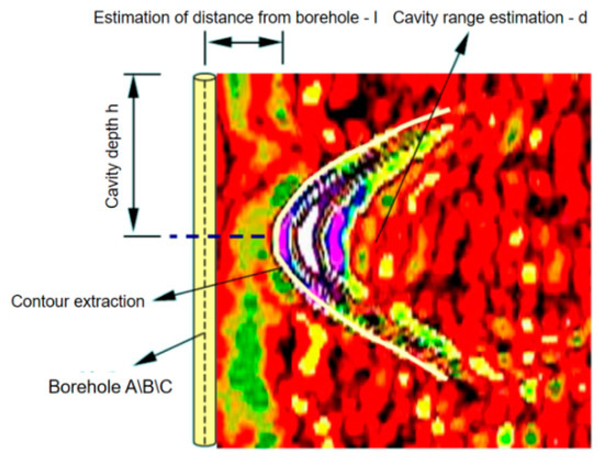
Figure 10.
Echo curve extraction and estimation in borehole A, B or C.
Through the comprehensive interpretation of the data of borehole optical imaging, borehole radar and borehole directional acoustic scanning section, it can better reflect the geological information such as the shape characteristics of the rock in the test area, the distribution of fractures, joints, fracture zones and veins in the rock mass.
4. Case Analysis
4.1. Project Overview
This paper takes the Kunming Changshui International Airport Project as an example to analyze. The project area is widely distributed with carbonate rocks such as bioclastic limestone, tiger porphyry limestone mixed with arenaceous limestone, dolomitic limestone, etc. The single layer of carbonate rocks is relatively thick, strongly affected by geological structure and joint fissures have developed. Under long-term weathering, denudation and water action, it easily forms dissolution ditches, dissolution channels, karst caves, stone buds and stalagmites. The engineering geological and hydrogeological conditions of karst morphology such as karst depressions and funnels, as well as surface collapse and soil caves caused by karst development are very complex. The geomorphic features of the site can be divided into denuded peneplain and denuded hill. The overburden layer is composed of Quaternary artificial fill layer, Quaternary vegetation layer and Quaternary eluvial layer. The alluvial–proluvial layer is hard plastic to soft plastic secondary red clay, which is generally distributed in karst depressions. The eluvial–diluvial layer is hard plastic to soft plastic red clay, which is widely distributed in the eroded and denuded plains, eroded hills and slopes. The bedrock includes the limestone of the Qixia section of the lower Permian Yangxin Formation, the mudstone of the lower Permian inverted stone formation, the limestone of the middle Carboniferous Weining Formation, the dolomite of the upper Devonian Zaige Formation and the structural breccia near the F10 fault. The occurrence forms of groundwater in rock mass are pore water, fissure water and karst water. According to the burial conditions and the distribution characteristics of the aquifer, it is divided into layered fissure water and weathered fissure water. According to the difference of the space and form of the underground water, the karst water is divided into karst fissure cave water and karst fissure water. Its task is to find out whether there are adverse geological phenomena, and provide geotechnical technical parameters and treatment plan suggestions required for the prevention and treatment of adverse geological phenomena.
Since the karst in this area is relatively developed, and there are adverse geological problems such as soluble rock and a large-scale fracture zone, in order to further investigate and analyze the distribution, burial depth and development degree of karst caves, and carry out targeted research, a special geological survey of karst has been carried out. In order to further explore some geological features of the area, entrusted by the engineering survey unit, the borehole optical imaging technology, borehole directional acoustic scanning technology and borehole radar technology are used for comprehensive survey of some boreholes. This paper takes three boreholes (ZK I, ZK II, ZK III) as examples to analyze and elaborate. The borehole multi-source data acquisition equipment is shown in Figure 11. Among them, borehole optical imaging technology and borehole directional acoustic scanning technology were independently developed by the Institute of Rock and Soil Mechanics, Chinese Academy of Sciences. The borehole radar technology uses the SIR200 borehole radar system produced by the GSSI company and is equipped with a 100 MHZ antenna.
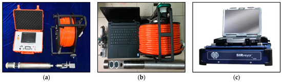
Figure 11.
Borehole multi-source data acquisition equipment. (a) Borehole optical imaging equipment. (b) Borehole directional acoustic scanning equipment. (c) Borehole radar equipment.
4.2. Data Acquisition
Through the acquisition of borehole optical images, the borehole wall expansion images of the whole hole section of the three boreholes in the survey area were obtained. Some of the borehole wall expansion images are shown in Figure 12. Figure 12a shows the expanded image of the borehole rock wall at 4.5–6.5 m corresponding to borehole ZK I. Figure 12a shows the expanded image of the borehole rock wall at 4.5–6.5 m corresponding to borehole ZKII. Figure 12a shows the expanded image of the borehole rock wall at 4.5–6.5 m corresponding to borehole ZK III. From Figure 12, we can intuitively grasp the distribution and morphological characteristics of the rock mass structure of the borehole. The adverse geological bodies in Figure 12a are mainly structural planes and small holes. The adverse geological bodies in Figure 12b are mainly karst caves and structural planes. The adverse geological bodies in Figure 12c are mainly karst caves.
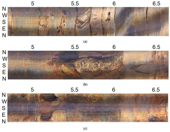
Figure 12.
Borehole wall in the borehole image. (a) Borehole ZK Ⅰ. (b) Borehole ZK Ⅱ. (c) Borehole ZK Ⅲ.
Through the acquisition of directional acoustic wave scanning data of boreholes, the full-pulse acoustic wave scanning data of the borehole wall of the three boreholes in the survey area were obtained. Some of the borehole acoustic wave scanning data are shown in Figure 13. Figure 13a shows the borehole directional acoustic scanning data at 4.5–6.5 m corresponding to borehole ZK I. Figure 13b shows the borehole directional acoustic scanning data at 4.5–6.5 m corresponding to borehole ZK II. Figure 13c shows the borehole directional acoustic scanning data at 4.5–6.5 m corresponding to borehole ZK Ⅲ.
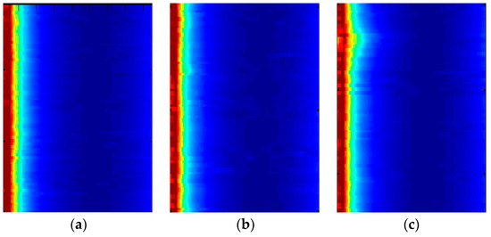
Figure 13.
Directional acoustic scanning of borehole. (a) Borehole ZK I. (b) Borehole ZK II. (c) Borehole ZK III.
Through the acquisition of the borehole radar technology, the borehole wall radar detection data of the whole borehole section of the three boreholes in the survey area were obtained. Some of the borehole radar data are shown in Figure 14. Figure 14a shows the borehole radar detection data at 4.5–6.5 m corresponding to borehole ZKI. Figure 14b shows the borehole radar detection data at 4.5–6.5 m corresponding to borehole ZKII. Figure 14c shows the borehole radar detection data at 4.5–6.5 m corresponding to borehole ZK Ⅲ. The image in Figure 14 shows the horizontal direction of drilling depth, with the left side representing 4.5 m and the right side representing 6.5 m. The image in Figure 14 is the reflection time of the radar wave in the longitudinal direction.

Figure 14.
Borehole radar data. (a) Borehole ZK I. (b) Borehole ZK II. (c) Borehole ZK Ⅲ.
4.3. Comprehensive Analysis
From ZK I, ZK II and ZK III borehole unfolding images, the distribution characteristics of the structural plane of the drilled rock mass and the texture characteristics of the rock can be clearly seen. The digital image processing technology is used to analyze the occurrence of the structural plane of each borehole rock mass, and the geometric parameter information such as the occurrence of the structural plane, gap width, spacing, etc., can be obtained, and the statistics and grouping can be carried out. The corresponding contour density nephogram and rose diagram of the structural plane are shown in Figure 15. Figure 15a,b shows the structural plane characteristics corresponding to borehole ZK I. Figure 15c,d shows the structural plane characteristics corresponding to borehole ZK II. Figure 15e,f shows the structural plane characteristics corresponding to borehole ZK III.

Figure 15.
Contour density nephogram and rose map of structural plane. (a) Contour density nephogram of borehole ZK Ⅰ. (b) Rose diagram of borehole ZK Ⅰ. (c) Contour density nephogram of borehole ZK II. (d) Rose diagram of borehole ZK II. (e) Contour density nephogram of borehole ZK Ⅲ. (f) Rose diagram of borehole ZK Ⅲ.
Borehole radar detection is based on the different reflection amplitude and phase of the electromagnetic wave when it encounters different reflection interfaces to judge the change of the propagation medium ahead. The difference in the dielectric constant of the medium determines the intensity of electromagnetic wave reflection and its phase. The change of lithology, structure, weathering degree and water content will affect its dielectric constant. The interpretation of radar test data is based on the radar image of the field test; the data processing is carried out first, and then the abnormal analysis of the image that can be interpreted is carried out. According to the shape and characteristics of the anomaly and the attenuation of the electromagnetic wave, the geological origin of the wave impedance interface can be determined so that the geological conditions within the test range can be explained. After completing the acquisition and analysis of the radar data of the three boreholes, the borehole radar data are comprehensively interpreted in combination with the borehole image data and borehole directional acoustic scanning data, and the results are shown in Figure 16.
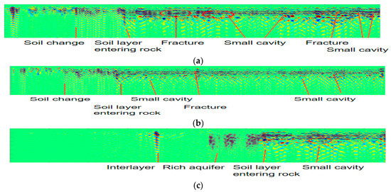
Figure 16.
Comprehensive interpretation of borehole radar data. (a) Borehole ZK Ⅰ. (b) Borehole ZK Ⅱ. (c) Borehole ZK Ⅲ.
It can be seen from Figure 16a that there are mainly cracks and small holes at different depths of borehole ZK I. It can be seen from Figure 16b that cracks and small holes mainly exist at different depths of borehole ZK II. It can be seen from Figure 16c that there are mainly small holes at different depths of borehole ZK II. In the survey of borehole holes using borehole optical imaging technology, the structural characteristics of rock mass inside the borehole can be effectively observed and measured, and the distribution characteristics of the structural plane of the borehole rock mass and the texture characteristics of the rock can be clearly seen. At the same time, the geometric parameter information such as the occurrence of the structural plane, gap width, spacing and so on can also be obtained. However, it is difficult to determine whether the rock mass structure around the borehole is abnormal by using borehole optical imaging technology. In addition, it is difficult to predict the extent of extension and development trend of the rock mass structural plane in a certain range far from the borehole. In the survey of boreholes using borehole radar technology, it can effectively judge the possible abnormal rock mass structures around the borehole, such as karst caves and cracks. However, the data obtained by using the borehole radar system alone are multi-solution and directionless, and it is difficult to obtain the dielectric constant of rock mass, which leads to difficulty in accurately defining the range of abnormal structures. At the same time, the width of rock mass fracture cannot be accurately given. In the exploration of boreholes by using directional acoustic scanning technology, the karst caves through the boreholes can be effectively found and measured, the buried depth of the karst caves can be determined and the geometric shape of the karst caves can be measured. However, it is difficult to obtain the rock mass structure of the borehole wall and the surrounding rock mass structure of the borehole only by relying on the borehole acoustic scanning system.
Therefore, by fusing the multi-source data of three kinds of boreholes, they can complement and improve each other, and improve the comprehensive interpretation accuracy. Through the method described in this paper, combined with the analysis of the crack extension range, the visualization results of the adverse geological bodies in the karst development area of the three boreholes are shown in Figure 17. Figure 17a is the unfilled vertical view, in which the cracks are represented by circular lines. Figure 17b shows the unfilled E–W orientation, in which the cracks are represented by disk lines. Figure 17c shows the unfilled N–S orientation, in which the crack is represented by a disc filled with color. Figure 17d shows the filled Side view, in which the cracks are represented by colored disks. Figure 17e shows the filled E–W orientation, in which the cracks are represented by colored filled discs. Figure 17f shows the filled N–S orientation, in which the cracks are represented by colored filled disks. The “Unfilled” in Figure 17 refers to the use of circular curves to represent cracks. The “Filled” in Figure 17 refers to the disc surface filled with different colors to represent the cracks.
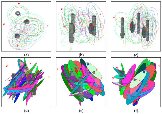
Figure 17.
Spatial visualization of adverse geological bodies. (a) Unfilled vertical view. (b) Unfilled E–W orientation. (c) Unfilled N–S orientation. (d) Filled side view. (e) Filled E–W orientation. (f) Filled N–S orientation.
It can be seen from Figure 17 that the visualization results of the adverse geological bodies in the karst development area of the three boreholes can not only present the texture characteristics of the borehole wall, but also realize the three-dimensional visualization of the structure of the adverse geological bodies between the three boreholes. This is mainly because the borehole optical imaging technology in the multi-source borehole data can clearly see the distribution characteristics of the structural plane of the borehole rock mass and the texture characteristics of the rock. At the same time, the geometric parameter information such as the occurrence, gap width and spacing of the structural plane can also be obtained. The borehole directional acoustic scanning technology in multi-source borehole data can effectively find and measure the karst cave through the borehole, and realize the judgment of the buried depth of the karst cave and the measurement of the geometric shape of the karst cave. At the same time, it can also effectively reflect the distribution characteristics of the near-field rock mass structure of the borehole-surrounding rock. The borehole radar technology in multi-source borehole data can effectively identify the possible abnormal rock mass structures around the borehole, such as karst caves and fractures. On the basis of multi-source borehole data, the comprehensive interpretation and analysis method proposed in this paper can realize the effective fusion and interpretation of multi-source data, and realize the three-dimensional visualization of adverse geological bodies in karst development areas. Through comparison with other geophysical prospecting methods and geological data, it is found that the detection results are more accurate and the detection efficiency is higher. Through limited geological boreholes, the refined detection of geological structures within the region can be realized. The method described in this paper can provide an effective technical means for fine detection of adverse geological bodies in karst development areas.
5. Conclusions
Through in-depth research and analysis of drilling optical imaging technology, drilling directional acoustic scanning technology and drilling radar technology, this paper realized the joint interpretation and fusion of three kinds of detection data, and lay an important theoretical and methodological foundation for the fine detection technology of adverse geological bodies in karst development areas. Because the technical method in this paper integrates three advanced detection technologies, in addition to effectively observing the structural characteristics of the rock mass from the hole, effectively judging the possible abnormal structures around the hole, and effectively finding and measuring the karst caves through the hole, it can also effectively realize the three-dimensional visualization of the unfavorable geological bodies in the karst development areas. This also provides the development characteristics of the unfavorable geological bodies in the karst development area. The judgment of development scale and extension direction provides more intuitive basic data. The results can provide more abundant and comprehensive exploration data for the fine exploration of geological bodies in the survey area. This technology can become a new and effective survey method in engineering geological surveys by improving the survey quality, shortening the survey period, reducing the cost, and ensuring the safety, stability and economy of the project overall.
Author Contributions
Conceptualization, W.L.; methodology, J.W.; resources, S.S. and H.X.; supervision, F.W. All authors have read and agreed to the published version of the manuscript.
Funding
This research was funded by the National Natural Science Foundation for the Youth of China (No. 41902294), the Open Projects Foundation of State Key Laboratory for Health and Safety of Bridge Structures (No. BHSKL-20-05-GF).
Institutional Review Board Statement
Not applicable.
Informed Consent Statement
Not applicable.
Data Availability Statement
All data, models and code generated or used during the study appear in the submitted article.
Acknowledgments
All the images and data are from our actual tests and permitted by the owners. We are compliant with ethical standards, and all authors declare that this paper has no conflicts of interest. Finally, we are grateful for the many helpful and constructive comments from many anonymous reviewers.
Conflicts of Interest
The authors declare no conflict of interest.
References
- Jiang, Y.L.; Kang, W.F.; Zhang, N. Application of High Density Resistivity Method to Karst Exploration. J. East China Inst. Technol. 2011, 34, 452. [Google Scholar]
- Xue, Y.; Ranjith, P.G.; Gao, F.; Zhang, Z.; Wang, S. Experimental investigations on effects of gas pressure on mechanical behaviors and failure characteristic of coals. J. Rock Mech. Geotech. Eng. 2022, 15, 412–428. [Google Scholar] [CrossRef]
- Gourmelen, G. A Dynamically Reconfigurable Autonomous Underwater Robot for Karst Exploration: Design and Experiment. Sensors 2022, 22, 3379. [Google Scholar]
- Bosch, F.P.; Müller, I. Improved karst exploration by VLF-EM-gradient survey: Comparison with other geophysical methods. Near Surf. Geophys. 2005, 3, 299–310. [Google Scholar] [CrossRef]
- Nazar, A.; Doloei, J. Geophysical Prospecting Methods of Seismic Borehole, Seismic Refraction and Geoelectric in Engineering Studies. J. Phys. Earth 2007, 2, 65–70. [Google Scholar]
- Eisner, L.; Hulsey, B.J.; Duncan, P.; Jurick, D.; Werner, H.; Keller, W. Comparison of surface and borehole locations of induced seismicity. Geophys. Prospect. 2010, 58, 809–820. [Google Scholar] [CrossRef]
- Xue, Y.; Liu, J.; Liang, X.; Li, X.; Wang, S.; Ma, Z.; Zhang, S.; Jiao, X. Influence mechanism of brine-gas two-phase flow on sealing property of anisotropic caprock for hydrogen and carbon energy underground storage. Int. J. Hydrogen Energy 2023, in press. [Google Scholar] [CrossRef]
- Tian, M.Z.; Song, H.B.; Sun, J. Geophysical prospecting high technologies of marine gas hydrates. Prog. Geophys. 2000, 15, 1–6. [Google Scholar]
- Yuan, G.Q.; Xiong, S.Q.; Meng, Q.M.; Zhou, X.; Lin, P. Application Research of Geophysical Prospecting Techniques. Acta Geol. Sin. 2011, 85, 1744–1805. [Google Scholar]
- Zhang, Z.; Li, Z.; Xu, G.; Gao, X.; Liu, Q.; Li, Z.; Liu, J. Lateral abutment pressure distribution and evolution in wide pillars under the first mining effect. Int. J. Min. Sci. Technol. 2023, in press. [Google Scholar] [CrossRef]
- Banks, D.; Odling, N.E.; Skarphagen, H.; Rohr-Torp, E. Permeability and stress in crystalline rocks. Terra Nov. 1996, 8, 223–235. [Google Scholar] [CrossRef]
- Manoutsoglou, E.; Lazos, I.; Steiakakis, E.; Vafeidis, A. The Geomorphological and Geological Structure of the Samaria Gorge, Crete, Greece—Geological Models Comprehensive Review and the Link with the Geomorphological Evolution. Appl. Sci. 2022, 12, 10670. [Google Scholar] [CrossRef]
- Steiakakis, E.; Monopolis, D.; Vavadakis, D.; Manutsoglu, E. Hydrogeological research in Trypali carbonate Unit (NW Crete). In Advances in the Research of Aquatic Environment; Springer: Berlin/Heidelberg, Germany, 2011; pp. 561–567. [Google Scholar] [CrossRef]
- Stober, I.; Bucher, K. Origin of salinity of deep groundwater in crystalline rocks. Terra Nov. 1999, 11, 181–185. [Google Scholar] [CrossRef]
- Wang, J.; Wang, C.; Hu, S.; Han, Q.; Wang, Y. Study on the extraction method of structural plane parameters from borehole images. Geotech. Mech. 2017, 38, 3074–3080. [Google Scholar]
- Wang, J.; Wang, C.; Tang, X. A method for determining the three-dimensional contour of the void based on the ultrasonic scanning technology in the borehole. J. Yangtze River Acad. Sci. 2018, 35, 104–109. [Google Scholar]
- Wang, J.; Wang, C.; Hu, S.; Han, Z. Survey accuracy analysis of panoramic borehole optical imaging technology. J. Rock Mech. Eng. 2015, 34, 4038–4046. [Google Scholar]
- Wang, J.; Wang, C.; Du, Q.; Luo, P.; Huang, J. Research on 3D visualization of geological boreholes based on photo-acoustic combination measurement. Chin. J. Rock Mech. Eng. 2023, 42, 649–660. [Google Scholar]
- Wang, J.; Chen, W.; Wang, Y.; Zou, J. Coral reef pore recognition and feature extraction based on borehole image. Mar. Georesources Geotechnol. 2021, 40, 159–170. [Google Scholar] [CrossRef]
- Wang, J.; Xu, H.; Zou, J. Fine detection technology of rock mass structure based on borehole acousto-optic combined measurement. Measurement 2022, 187, 110259. [Google Scholar] [CrossRef]
- Wang, J.; Wang, C.; Han, Z.; Jiao, Y.; Zou, J. Study of hidden structure detection for tunnel surrounding rock with pulse reflection method. Measurement 2020, 159, 107791. [Google Scholar] [CrossRef]
- Wang, J.; Wang, C.; Han, Z.; Zou, X.; Wang, Y.; Wang, C.; Hu, S. Characteristic Parameters Extraction Method of Hidden Karst Cave from Borehole Radar Signal. Int. J. Geomech. 2020, 6, 04020113. [Google Scholar] [CrossRef]
- Olsson, O.; Falk, L.; Forslund, O.; Lundmark, L.; Sandberg, E. Borehole radar applied to the characterization of hydraulically conductive fracture zones in crystalline rock. Geophys. Prospect. 2010, 40, 109–142. [Google Scholar] [CrossRef]
- Kim, J.H.; Cho, S.J.; Yi, M.J. Borehole radar survey to explore limestone cavities for the construction of a highway bridge. Explor. Geophys. 2004, 35, 80–87. [Google Scholar] [CrossRef]
- Wang, J.; Xu, H.; Chen, W.; Wang, C.; Han, Z. Evaluation method of rock mass structure integrity based on borehole multivariate data. Int. J. Geomech. 2022, 22, 04021248. [Google Scholar] [CrossRef]
- Wang, J.; Wang, C.; Huang, X.; Zou, J. Research on multi-frequency ultrasonic scanning detecting technology of cavity in the test borehole. Bull. Eng. Geol. Environ. 2020, 80, 1249–1264. [Google Scholar] [CrossRef]
Disclaimer/Publisher’s Note: The statements, opinions and data contained in all publications are solely those of the individual author(s) and contributor(s) and not of MDPI and/or the editor(s). MDPI and/or the editor(s) disclaim responsibility for any injury to people or property resulting from any ideas, methods, instructions or products referred to in the content. |
© 2023 by the authors. Licensee MDPI, Basel, Switzerland. This article is an open access article distributed under the terms and conditions of the Creative Commons Attribution (CC BY) license (https://creativecommons.org/licenses/by/4.0/).