Abstract
Non-destructive testing (NDT) of aerospace structures has gained significant interest, given its non-destructive and economic inspection nature enabling future sustainable aerospace maintenance repair operations (MROs). NDT has been applied to many different domains, and there is a number of such methods having their individual sensor technology characteristics, working principles, pros and cons. Increasingly, NDT approaches have been investigated alongside the use of data fusion with the aim of combining sensing information for improved inspection performance and more informative structural health condition outcomes for the relevant structure. Within this context, image fusion has been a particular focus. This review paper aims to provide a comprehensive survey of the recent progress and development trends in NDT-based image fusion. A particular aspect included in this work is providing critical insights on the reliable inspection of aerospace composites, given the weight-saving potential and superior mechanical properties of composites for use in aerospace structures and support for airworthiness. As the integration of NDT approaches for composite materials is rather limited in the current literature, some examples from non-composite materials are also presented as a means of providing insights into the fusion potential.
1. Introduction
Competitiveness in aviation operations has depended on the constant adoption of continuous flights, requiring sustainable maintenance services. A maintenance and repair organisation (MRO) is a service establishment that provides maintenance, repair and overhaul functions to operators to keep their aircraft utilised. While airlines had their engineering departments to perform maintenance at the initial time of commercial aviation, outsourcing options have become popular due to the increment in operation volume [1]. In addition, regulatory authorities have forced companies to organise their cores as directives of regulations. MROs have introduced flexibility between aviation operation and maintenance processes, providing a variety of special maintenance centres that specialise in a particular component, such as engine or structural maintenance [2]. MROs have the vital mission in the aviation market of not only maintaining the sustainability of operations but also reducing costs because aircraft grounding impacts efficiency and “the ratio of” flight time to operating expenses. The daily cost of an aircraft being out of operation can be considered to be GBP 200,000 on average [3] (based on reasonable average estimates: a narrow body aircraft (200 passengers × 8 journeys × GBP 100 = GBP 160,000); wide body (350 passengers × 1 journey × GBP 800 = GBP 280,000)). Moreover, unscheduled maintenance due to unexpected problems also highly impacts expenses. According to the IATA, wide-body jets were predicted to have a cost of more than USD 6.5 billion in unplanned maintenance owing to delays and cancellations in 2017. Appropriately scheduled maintenance, including shorter downtimes, avoiding unnecessary disassembly and minimizing unexpected delays and possible human errors, is crucial to reducing the grounding time of aircraft.
Structural components are a significant element in terms of inspection and hence maintaining airworthiness. MROs spend significant time checking structural components, which accumulates to typically ≈30% of the costs [4]. Note that hidden (non-visible) defects (damages) inside the structure hinder operation in the medium to longer term. Several conventional inspection methods need a removal process that lengthens the maintenance time. Advanced non-destructive inspection/technique (NDI/NDT) methods are already popular in structural checks for detecting the occurrence of any defect in an early stage. The NDT is a powerful tool for detecting damages in the structures that formed during both the manufacturing and service stages [5,6]. However, it is a formidable task to design a generic inspection procedure, considering the restrictions caused by regulations, operations, capabilities and costs. Obtaining more informative and determinative inspection outcomes should provide cost-effective maintenance which reduces the time and effort for individual inspection methods, especially after the pandemic period, in which there was a high workforce loss of 2.3 million personnel in global aviation [7].
Composite structures have become attractive for many industrial sectors due to their good strength and stiffness per unit weight [8,9,10]. In aviation, the volume of the composite structures used in an aircraft, such as the fuselage, wings, and empennage, has risen day by day. Accordingly, it is a vital requirement to identify possible damage to aircraft structures regarding airworthiness. It should be noted that understanding the structure will help in exploring the problems and related solutions. For this reason, possible defect types that can occur in a composite structure must first be understood. Then, the characterisation and measuring of a defect in the structure must be performed precisely if possible. Here, measuring refers to correctly establishing the defect’s location, size and significance. Structural health monitoring (SHM) methods have ensured useful strategies for inspecting aerospace composites in various recent studies [11,12,13,14].
Defect localisation and characterisation are vital steps in NDT application, with their own parameters that affect maintaining sustainable aviation operation and airworthiness. That structural recognition and comprehensive knowledge of possible defects will ease maintenance operations, followed by sustainable aviation, is not in doubt. In this article, the fusion approaches already used in NDT studies have been investigated in terms of application potential for aerospace structures. The related algorithms and their evaluation are presented and discussed. It should be emphasised that NDT fusion is still a fresh research topic, and utilizing image fusion strategies for NDT defect detection application when applying the individual inspection methods is not satisfactory [15]. This comprehensive review study, which stems from a current PhD study exploring advanced NDT fusion of an ultrasonic phased array and pulsed thermography for inspection applications in composite structures, contributes the following:
- It introduces the current studies on NDT image fusion and evaluation strategies;
- It provides a reference source for the NDT-based fusion attempts;
- It reports the limited amount of work existing in fusing NDT techniques (particularly for composite structures);
- It fills the research gap of comprehensively reviewing image fusion for NDT inspection (particularly towards composite structures).
The rest of this paper is structured as follows. A brief discussion of the primary NDT techniques is given in Section 2. The basic principles of image fusion are discussed in Section 3. Section 4 includes fusion strategies and rules for various NDT techniques discussing principles and examples. Section 5 discusses the evaluation of fusion, focusing on performance metrics. Section 6 provides insights from the survey into NDT fusion and future prospects. Conclusions are drawn in Section 7.
2. NDT Method Preliminaries
There is a variety of inspection technology approaches. Their use depends on the structure or material to be inspected, cost and effectiveness. Method-wise, they offer pros and cons, and hence a requirement analysis can be a good starting point to be able to select an appropriate method for the relevant inspection application. Note that each technique utilises a different sensing technology and property. A useful categorisation of NDT methods relative to defect types has been seen in previous works [16,17,18]. Table 1 lists a snapshot of the standings of such methods, which relate to those presented in this review paper [17]. We also include an indicator of “applicability” as suitable, weak or limited. This relates to the level of information outcome of the NDT method for the said defect type and defect detection performance (ability). For example, X-ray-based NDT is challenged by detecting delamination defects in general, with open delamination possible to detect using X-ray computed tomography (CT). Moreover, we give a brief description of these main inspection methods.

Table 1.
NDT method standings relative to defect types.
X-ray radiography is a well-established technique which provides a permanent record (using the X-ray-sensitive film) and is used in NDT inspection. X-rays (or -rays, which have a better penetration ability) passing through the sample and the radiation intensity are different if any defects are encountered (see Figure 1c). This principle was successfully used to discriminate different materials for an object by using neutron and X-ray beams simultaneously [19]. However, it can provide a 2D line scan, and it might be difficult to identify the depth information in the case of defect characterisation or localisation. X-ray CT is a developed version that can give 3D images with depth information. The authors of [20] applied X-ray CT with terahertz testing to obtain 3D images for CFRP composite defect characterisation. Even though both can give 3D images using different wavelengths and frequencies of electromagnetic radiation, they were used together to obtain the optimum contrast and resolution. It should be noted that the inspection process is simple, while the equipment can be complex and have a high cost. Radiography also raises health concerns and is performed with care. In addition, both have limited capabilities because of the orientation of delamination or crack defects, as shown in Table 1 [17].
Another important method is ultrasonic inspection, which uses ultrasound wave propagation inside materials (Figure 1b). Using analysis of the reflections because of the abnormalities in an internal structure allows measuring the characteristics such as the thickness or depth of any defect. Although advanced ultrasonic tools provide 3D C-scans and cross-sectional B-scans to obtain sufficient information about a structure; quantifying and locating defects might be challenging and require complementary techniques when multiple close reflections [21] or near-surface defects [22] occur. The authors of [22] also showed the challenging points of processing ultrasonic data due to the multiple echoes caused by structural noise.

Figure 1.
Basic representations of thermographic, ultrasonic, X-ray and eddy current NDT methods. (a) Schematic representation of pulsed thermography [23]. (b) Schematic representation of ultrasonic testing [24]. (c) Schematic representation of X-ray radiography. (d) Eddy current defect representation [25].
An efficient method for surface and near-surface defects is infrared thermography, which uses thermal wave propagation caused by temperature differences. Figure 1a presents a basic schematic representation of pulsed thermographic inspection. The authors of [26] presented an effective low-velocity impact characterisation for the matrix, delamination and fibre damage of a GFRP structure with thermography. Surface temperature maps have been used to observe local temperature changes and maximum temperature differences to help identify defect types. It should be noted that thin materials restrict infrared thermography due to the challenges of heat penetration into deeper regions of the material [27].
Liquid penetrant testing that uses the capillary action principle might provide a practical solution when surface examination of mass-produced items is performed [28]. A particular liquid, known as a penetrant, fills any discontinuities that may be present when applied to a specimen’s surface. Thus, it can be detected by fluorescence or human eyes according to the penetrant’s dye type. The main limitation of this technique is being restricted to surface or open-to-surface defects.
As can be seen from Table 1, the magnetic particle and eddy current (Figure 1d) methods are the other surface-effective techniques that use similar principles of forming regular magnetic fields on uniform materials. In the case of a discontinuity, the magnetic field deforms because it tends to follow the path having the least resistance [28,29]. However, magnetic particles and eddy currents are limited by the material types of ferromagnetic and conductive types, respectively.
Finally, acoustic emission is a reliable and real-time technique that detects the materials’ transient stress waves for early fault detection [30]. While the approach is highly sensitive to small changes in an active defect, it tends not to be suitable for constant (static) defects. Moreover, it seems to be an attractive method for electrical defects rather than mechanical ones, as well as having issues with the defect size and shape aspects [31].
3. Image Fusion
Fusion is a valuable process that combines or integrates information from different sensors or sources. Image fusion is the technique of integrating several input images of the same scene into a single fused image, intending to synthesise better quality and perception of the image features. Note that an image is viewed as a light intensity function , where x and y are the spatial coordinates of each pixel and f refers to the proportional value of the brightness at each coordinate [32]. Image fusion can combine the brightness, colour, distance, temperature and other scenery features of images. It should be noted that image fusion does not simply mean “matching” or “overlaying” of multiple images; it is a process followed to form a renewed and more meaningful image outcome [33]. Image fusion can reduce data dimensionality while keeping important information content, hence supporting a lower storage cost [34]. In principle, image fusion is seen as performing three main steps: registration, information fusion and representation (refer to Figure 2) [35].
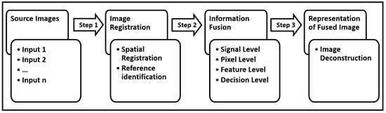
Figure 2.
The main steps of a generic fusion structure.
NDT-based image fusion is a challenging topic due to the varied defect sensitivity and failure mechanisms of the inspection methods. However, these methods incorporate complementary features to obtain reliable and accurate defect characterisation and take the best action against an existing situation [36]. In such a fusion application, registration is the first significant step in having a proper reference for a fused image. The information from NDT sources should be aligned correctly to obtain the sense results. As well as the common feature point-based registration, such as for corners or edges, the authors of [37] presented a type of marker-based referencing which uses the highly reflective or emissive marks on the surface of the inspected material when the feature points are not detectable enough. As a vital matter, especially in the medical image fusion field, registration has been widely investigated with methods ranging from transformation or similarity-based methods [38,39] to novel AI-based strategies [40,41] in the literature.
Similar to other fields, NDT-based fusion can be classified as level-based by the forms of information flow: signal-level, pixel-level, feature-level and decision-level fusion [42]. In signal-level fusion, a fused signal has been formed to obtain better quality by combining raw sensor signals, which can be modelled as a random variable. As an example, the authors of [43] applied superposition-based fusion at the signal level to fuse simulated defect and experimental defect-free noise. Figure 3 shows a superposition outcome that is comparable to the presence of the defect in the sample. The authors have stated that the outcomes have accurate amplitudes for defects as well as back walls and shadowing effects due to the model’s destructive signal interfering with the back wall signal. This level of fusion has the highest registration needs in the time and space domain because of considering an optimal signal distribution problem [44].
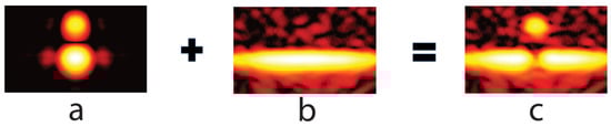
Figure 3.
(c) An example representation for signal-level combination for a noise-free defect simulation and defect-free experimental noise. (a) Simulated noise-free defect. (b) Experimentally measured defect-free noisy back wall [43].
Pixel-level fusion integrates the physical parameters of the source pixels given at specific spatial locations and their neighbourhoods and creates a pixel for the fused image. The authors of [45] applied the pixel-wise averaging, PCA and wavelet methods by considering the individual pixel values for each method and combining them. Although this combination has a better depth resolution and signal-to-noise ratio than the source images, it is restricted by the large size of the data to be calculated and is time-consuming.
The benefit of image fusion based on feature-level fusion, which acts on properties such as the edge, shape and texture, is that it achieves a certain amount of information compression and supports real-time processing. A color moment (including the mean, variance and skewness features) and texture (mean, standard deviation, smoothness, third-order moments, consistency and entropy features) fusion example was carried out in [46] to use the results as the input for a recognition training algorithm. The main advantage of this fusion is having fewer dimensional feature vectors thanks to the compression. In addition, the study proved that fusion has increased recognition accuracy and reduces the false detection rate.
Finally, decision-level fusion is a cognitive strategy where source images are converted to generate an independent target attribute estimation which is already a representative symbol for information extraction [44]. A partial density-based fusion was proposed in [47], using the computation of the single-sensor spatial density estimation. The calculated partial densities, instead of feature extraction or pixel-wise merging, are merged with a basic summation fusion rule ignoring the maximum value to provide false alarm reduction. The main advantage is that this technique explicitly treats the localisation uncertainty caused by registration problems. Consequently, the selection of the fusion level that will be applied depends on various parameters, such as the image sources, processed data type and information that the image has. This should be performed in a scrutinizing manner according to the overall expectations from the sources and fusion. Now, we will present current fusion applications that are already used for different materials and various fields within a generic classification according to the methods they are based on in the next section.
4. Image Fusion Applications in NDT Inspection
4.1. General Algebraic Approaches
General algebraic (basic mathematical) approaches have been utilised to combine the source signals, features or estimations pixel-wise as a fusion rule. The selection of the appropriate fusion rule might depend on the target that needs to be achieved and the nature of the data collected from different sources. For instance, while division and subtraction are suitable for detecting temporal changes in different measurements, the maximum approach might be more applicable to finding complementary information, as seen in [48]. The study performed a porosity and distribution analysis for concrete structures using ultrasonic and ground-penetrating radar (GPR). After the processing (weighting and filtering datasets) and reconstruction (synthetic aperture focusing technique (SAFT)) steps for both individual methods, the amplitude values of both methods are added to obtain improved depth information, adapting the depth point of the maximum amplitude.
The size of the dataset is another crucial parameter in selecting the fusion rule that will be implemented. For example, the data size must be the same for an addition or division operation. In addition, a data acquisition system might affect the selection of fusion methods due to the nature of the produced data. A bimodal imaging system may need supervision to prevent interference while using two separate imaging systems. Dual-imaging fusion based on X-ray and neutron images has been offered for material identification using attenuation differences [19]. It has been used as a single-electron linear acceleration system with a slight time delay to prevent the system from that type of interference. It should be noted that here, the acquisition systems for X-ray and neutron inspection have almost the same beam geometry, and data are ready to fuse directly. Pixel-wise matching has been performed using extracted neutron attenuation and photon attenuation values compared with the neutrons and photons of air. As a result of this pixel-wise fusion, a bivariate histogram has been provided to identify different materials and their thicknesses without prior knowledge.
The basic mathematical fusion rules can also be used mainly for comparison or complementary with other fusion rules. A good example application of this is in [49], which includes the basic rules, wavelets and decision-level fusion (kernel density estimation (KDE)) together. A steel-bearing shell specimen with 15 surface grooves and specific dimensions was used experimentally. Although the sum and max fusion rules provided poor performance, all other rules showed a satisfactory flaw detection capability rather than the single-sensor yield. Another study in the manufacturing field [50] proposed pixel-based image merging to improve object measurement using the multi-energy stacks of computed tomography (CT) images. The primary purpose behind the fusion process is to eliminate measurement difficulties caused by the sample’s high aspect ratio (thickness to length) and the variety of absorbing materials. Fusion was applied by finding outshined pixels of different energy stacks, followed by replacing those pixels. A mean deviation-based evaluation was applied, and the fusion results showed less deviation than the mono-energetic measurement. Table 2 presents information on the material, defect and source details of the aforementioned studies. There are more studies available in the papers [46,51,52,53] that used these basic rules in a complementary manner. However, the details provided in the papers are limited. In addition, Table 3 has given mathematical expressions of related fusion rules.
Table 2.
Brief information on current studies which use general algebraic fusion rules.
Table 3.
Data fusion operations at signal level (amplitudes).
4.2. Principal Component Analysis
Principal component analysis (PCA) is a well-known statistical technique for reducing the dimensionality of a dataset. This is carried out via appropriate coordinate transformation. Here, the main idea is to retain the maximum possible variation while reducing the dimensionality of the dataset. The new set of variables, referred to as the principal components (PCs), is generated in such a way that the first few PCs retain most of the variation (in more detail, the first component retains the maximum variance, with the second one existing in the subspace that is perpendicular to the first PC) [54,55,56]. PCs are linear combinations or mixtures of the original data. Figure 4 illustrates the first and second uncorrelated dimensions as PCs. PCA has already been used in various domains, such as pattern recognition, image compression, dimensionality reduction and feature extraction [57,58,59,60], as well as NDT applications [61,62,63,64,65].
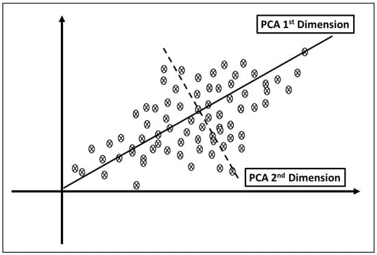
Figure 4.
Basic projection of PCs as linear combinations of original data.
In the context of NDT fusion, a pixel-level fusion using the PCA and DWT methods was proposed to detect inclusive defects (copper sheets) with different depths, sizes and shapes in a GFRP material [66]. Amplitude and phase images from active thermography, extracted using a Fourier transform, were fed for fusion as inputs. The principle components and wavelet coefficients shaped the input images for combination purposes. In terms of fusion efficiency, the metric used was the signal-to-noise ratio (SNR) between the inputs and fused images. It was highlighted in the work that the PCA fusion strategy increased the SNR for the inclusive defects considerably. A similar study [45], including Teflon inclusions of different depths and sizes for GFRP composites, applied pulse compression to thermographic images. For transmission, a low peak power and long-duration modulated wave was used, rather than a short duration and high peak power, to obtain a better depth resolution and SNR for the inhomogeneities in the structure. The study compared averaging-, PCA- and wavelet-based fusions, with the latter providing the highest SNR.
Within the remit of CFRP composite-related studies, (It is noted here that carbon fibre-reinforced polymer (CFRP) composites are the main composite structure used in aerospace structures rather than GFRP.) the authors of [67] proposed a fusion structure that utilises multi-frequency lock-in thermography. This approach explores the advantage of detection characteristics that provide different depth information for various frequencies. In addition, the authors proposed an optimum frequency selection approach considering the material thickness and thermal diffusivity. Phased images formed by the signal variation over time at each pixel were extracted in sequences that indicated thermal changes on the material surface. PCA was used to detect holes at different depths for a single image by decomposing a series of phase images to their principal components. A comparison between PCA-, wavelet- and multi-scale decomposition-based fusion was performed, and the former fusion approach provided the best edge sharpness and hole contrast detection.
Here, only the fusion strategies referring to composite materials are explained in detail. For completeness, we provide information on the fusion approaches that utilised different types of structures (however, the fusion application is a useful example to inform further work on composites) in Table 4 with their relevant citations.
Table 4.
A list of PCA-based studies for NDT image fusion.
4.3. Fourier Transform-Based Approaches
Fourier analysis is a well-known approach in mathematics, covering a large spectrum of applications (approximating a general function with the sums of more straightforward trigonometric functions). Fourier analysis decomposes an image into its sine and cosine components, with the transformation output representing the image in the frequency domain (the input image is the spatial domain). For completeness, general forms of Fourier synthesis and analysis equations, respectively, for a periodic sequence of [71] are shown below ( and N refer to Fourier coefficients and period, respectively):
Working in the frequency domain enables easier processing for image fusion. The work in [72] presents a useful example of Fourier-based NDT image fusion. Using a Gaussian function, the authors presented a cone-shaped filter in the Fourier domain of X-ray computed tomography (CT) and ultrasonic testing (UT). The fusion aimed to combine the advantages of the inspection methods, hence minimising issues such as noise, artefacts and low resolution. A test sample containing the specific dimensions of the internal channels was used to perform CT and UT volume measurements. The fused image provided reduced artefacts and improved the edge contrast compared with using the inspection technologies independently. It is noted that, as seen in many works in the literature, the Fourier transform has often been used as a tool to preprocess data prior to feeding them to the fusion rule.
4.4. Wavelet-Based Approaches
The wavelet transform is an appropriate tool to decompose images into high- and low-frequency components. This makes possible analysis of the features of data over a certain scale, such as the edges and texture for an image or the frequency for a signal. Unlike the Fourier transform, which offers a specific frequency wave, it can provide data representation for multiple scales with different versions of wavelets. Shifted and scaled versions of a wavelet can positively impact the resolution in the time or frequency domain according to the selected parameters. The wavelet transform aims to maintain a good resolution in the time and frequency domain, contrary to the Fourier transform [73,74].
For an image, the row and column directions must be handled independently when the original image is divided into four sub-band images. The two-level decomposition structure is illustrated in Figure 5 for illustration purposes. Each row’s data are first used to utilise the high-pass filter H and the low-pass filter L, and then the high- and low-frequency components of the row are obtained by downsampling of the two. The next step is the same in the column base and continuous for the next decomposition levels iteratively. The low-pass portion (LL), called the approximation or wavelet coefficients, contains the average image information, and the high-pass portion (i.e., detail coefficients) has the directional information of the original image. By using this approach recursively, multi-resolution wavelet analysis can be performed [75].
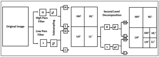
Figure 5.
Two-level wavelet decomposition structure (recursive filtering and subsampling).
The decomposition level and selection of the proper wavelet filter, one of the most important steps for wavelet application, should be decided according to the structure, aim of the transformation and the information that should be emphasised. The authors of [76] proposed a wavelet energy-based () filter selection method which considers that the minimum percentage of the approximation coefficients and detail coefficient will bring minimal noise. This is attributed to the minimum amount of low-frequency information in the approximation coefficient after decomposition. Additionally, a weighted risk factor-based decomposition, including automatic level selection, is used according to the maximum detail coefficients. The primary goal of the proposed strategy is to eliminate noise while maintaining appropriate defect information. The results show that the risk factor-based fusion provided more visual and qualitative detection than the minimum energy-based approach.
Moreover, a number of other studies in the literature attempted to interpret the effectiveness of the decomposition level and selected a filter using multiple options over a specific application [20,77]. For example, a hybrid image fusion structure of wavelet-based multi-scale transforms (W-MST) and saliency region analysis (SRA) was proposed to combine the advantages of the terahertz and X-ray CT techniques [20]. Here, the study compared and contrasted 36 fusion combinations, including various fusion rules, decomposition levels and basis functions. Experimental samples were formed using glass fibre (GFRB) with different-shaped inclusions and defects with various thicknesses and depths. First, saliency maps, which show the indication of the human eyes’ first focus in an image, were obtained for both methods. Then, the main outline in the low-frequency component and edge contour information of the high-frequency sub-bands were transmitted to the last fused image by W-MST. Assessment of these combinations was performed by calculating the standard deviation (SD), which shows the image’s grey level nature, and spatial frequency (SF), which provides the imaging resolution for the defect details. Among these combinations, the energy, average gradient and constant fusion strategies showed the highest increment between the source and fused images in terms of the two indicators. For completeness and useful information to the reader, Table 5 lists important current studies on wavelet-based fusion strategies for different materials and defects. These include the ones discussed in more detail in this section.
Table 5.
A summary of the current wavelet applications for NDT image fusion.
4.5. Learning-Based Approaches
Learning-based probabilistic methods have already become popular in the image fusion field due to their direct link to computer vision problems and capability of automatic feature extraction. In addition, they have significant potential for representing the complex characteristics and relationships of the source images and fusion results. Learning enables more AI-based approaches in inspection applications and can be a useful tool to the inspection expert, supporting more autonomy in inspection applications. In this section, we present studies that are already used for the fusion of NDT systems, with some insights into the proposed methods.
4.5.1. Neural Networks
Artificial neural networks (ANNs) are one of the most useful forms of machine learning (ML) in several fields, such as classification and pattern recognition. The high-speed processing offered by a highly parallel implementation represents ANNs’ greatest potential. The ability to create simple and accurate models from complicated natural systems with vast inputs is a strong benefit of ANN applications. They can behave as a functionalised management system similar to the human brain’s nervous functions. ANNs mimic the operations of an interconnected arbitrary number of nodes by traversing a number of levels with the input characteristics [86]. The basic components of an ANN’s structure can be considered to consist of inputs, weights, a transfer function, an activation function and bias [87]. The inputs refer to the measurements of the features that will be modified. The weights are the scalar multiplications responsible for evaluating each input’s significance and directionality. The transfer function merges the inputs into a single output value in order to apply the activation function. An activation function captures the information from the transfer function and transforms that into a more useful form, which will be used in the next stage. Bias can be considered a systematic error, given as extra input to the system due to the assumptions during the process [88]. The basic artificial neuron architecture, the so-called threshold logic unit (TLU), is demonstrated in Figure 6.
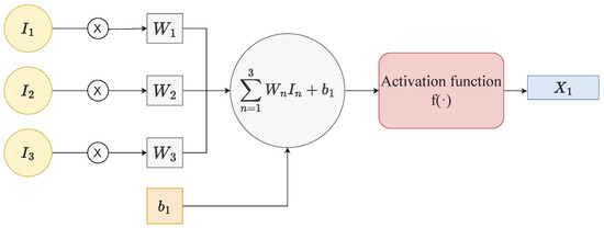
Figure 6.
Basic neuron architecture, called the threshold logic unit (TLU), showing inputs (I), weights (W), bias (b), activation function (f) and output (X) [89].
ANNs have been constructed by multi-neurons, which use weights that can learn and be changed after each iteration through neurons, depending on the accuracy. An ANN structure is able to make predictions in the form of regression or classification, followed by a training step for a particular dataset. A recent study [90], as an example, used an ANN structure to train eddy current (EC) impedance and ultrasonic amplitude inputs, aiming to overcome problems as a result of the blind zone of ultrasonics on the near-surface and the electromagnetic skin effect of the EC on the subsurface. The authors employed a database that included a simulation of signal propagation into an aluminium block with holes for estimating the depths and radii of the holes in a regression. The ANNs were also used to characterise and validate the study using real holes experimentally. Mean absolute error (MAE) calculations were performed to assess the accuracy of the defect estimation parameters. The experimental results show that the error of the depths and radius estimates was limited to 4 percent on average, although it showed a peak of 11 percent for one hole. It is stated that this complementary approach might be promising for investigating more complex structures and various defect types.
In the theme of the neural network, the recent study on multi-modal infrared image fusion used a hybrid fusion structure that included a non-subsampled shearlet transform and a pulse-coupled neural network [91]. Two types of impact-defected fibre-metal hybrid composite laminates were inspected by vibro-thermography (VT) and pulse thermography (PT). Three-step feature extraction, feature selection and a fusion method were applied as shown in Figure 7. Fourier analysis for the frequency domain features and intensity contrast criterion for the feature selection were used. Feature selection in the time domain was made using a temperature curve that allowed for determining the thermal contrast over time. For the fusion, images were decomposed by a shearlet transform, followed by the weighted mean and pulse-coupled neural network fusion for the low- and high-frequency sub-bands, respectively. The fusion results indicated a conspicuous improvement in crack contrast and detecting the boundary of deformation rather than a single excitation mode.
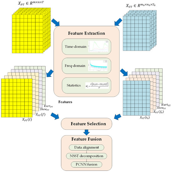
Figure 7.
An example demonstration of three-step integration framework: feature extraction, selection and fusion [91].
Another important structure for fusion studies is the convolutional neural network (CNN). This is one of the most beneficial tools for image analysis applications due to its advanced feature extraction ability through convolution operations instead of standard matrix multiplication. A CNN may use multiple convolution layers to obtain features hierarchically, max pooling layers to minimise image sizes and batch normalisation for reducing internal covariance. A loss function is used to find the difference between the expected and predicted results and tries to minimise them [41]. Historically, after AlexNet [92], various CNN-based algorithms have been proposed to gain a better understanding of image analysis cases. U-Net achieved an efficient feature extraction method even in a small dataset using structural segmentation [93]. ResNet was developed to overcome gradient degradation problems in the training of deep neural networks using a residual network [94]. After that, DenseNet was proposed to obtain a densely connected structure by engaging all layers with each other [95]. GoogLeNet has used an inception module that has multiple kernels of different sizes for convolution to ensure more efficient computation [96]. A couple of studies that have been published recently have focused on the fusion of NDT methods through neural networks to inspect various materials, from wooden cultural heritages to common composites [97,98,99,100,101,102]. Here, the text will not give the details of these approaches. (The interested reader can refer to the specific papers cited.) However, Table 6 demonstrates the sources and aims of those neural network-based research works in various fields. The use of learning approaches in NDT inspection can greatly benefit the field (classify and learn image properties, defects characteristics and features). However, their use in this field is still in its infancy. This is an important part of the PhD study this review paper stems from.
Table 6.
A summary of the recent neural network-based fusion studies for NDT methods.
4.5.2. Fuzzy Sets
Fuzzy logic is another technique that uses ambiguous or imprecise statements to simulate logical thinking. Fuzzy logic stems from the idea of fuzzy sets [103] and assigns a degree of membership to the elements of a system, often a real integer in the range of (where 0 denotes “completely false”, 1 denotes “completely true”, and values in between the range denote “partial truth”). This indicates a set of many-valued logics in which the truth values are viewed as levels of truth. The general workflow of a fuzzy logic approach is as follows [104]:
- Fuzzification: transform the data in the form of an uncertain language into the linguistic variables (fuzzy set or a membership function) together with the fuzzy components. In this way, the data can be processed using a classical binary method of “zero” and “one”.
- Inference: refer to a rule-based inference that the membership functions are combined with the fuzzy control rules, such as the mean of the maximum or minimum distance, to find the control outcome [105].
- Defuzzifcation: the fuzzy control outcome must be converted from linguistic variable to classical variable format.
From the point of view of NDT, defect characterisation is the primary implementation field to use entire methodologies, whether it is data collection or processing that data. An early study which introduced a fuzzy logic-based pixel fusion for three tomographic techniques that characterise different shape properties was presented at the end of the nineties [106]. Cylindrically shaped aluminium specimens that included two different thicknesses for the drilled side holes and a planar flaw were used. Here, the set was utilised to define the pixel’s membership level in a generated defect image. To be precise, the member pixels had a weight of 1, while others were between 0 and 1 according to the membership function. The weighted pixel amplitudes were summed to form a fused defect image. The study showed that the holes were clearly visible in the fused images, but the planar flaw was not evident in terms of size and shape. It was explained that the data acquisition configurations might change with the orientation of the defect. Lastly, the study does not contain any mathematical evaluation method, although it had sufficient discussion on the reasons for data acquisition issues. Table 7 demonstrates that the current studies on NDT image fusion have investigated aluminium materials and concrete structures so far. The scarcity of NDT combination attempts applied to composite materials also shows the potential for a number of different algorithms to be used in this area.
Table 7.
A summary of fuzzy set-based fusion approaches for NDT methods.
Research on material properties is a different application field of NDT inspection technologies. Inspecting concrete characteristics and determining physical properties was proposed by the authors of [108]. Because of difficulties in understanding the porosity, water saturation rate, elastic modulus, compressive strength, depth of carbonisation and chloride content of concrete structures, a complementary fusion of non-destructive information might improve the reliability. For this purpose, a fuzzy set-based possibility theory was chosen to combine this heterogeneous information for controlled produced specimens with different compositions. The fusion results were compared with the destructive measurement and had several differences. It has been claimed that such a fusion technique can be helpful in understanding the conflicts of the NDT methods. This can make it possible to have a critical evaluation of the results and provides for the creation of a confidence index for inspected structures. The proposed method has been considered encouraging for the water saturation and porosity rates. However, it is problematic in estimating the elasticity value. With a similar purpose, the authors of [109] proposed stress measurement of an aluminium alloy material using fuzzy combinator-based fusion. It has been claimed that a fused result might have 50 percent less error than individual inspection outcomes. Even though the combination of NDT methods can give more deterministic clues regarding the mechanical properties of inspected structures, it is clear that these contemporary approaches are highly limited.
4.5.3. Bayesian and Dempster–Shafer Methods
The Dempster–Shafer (D-S) method, known as evidence theory or belief functions, can be seen as a generalised form of the Bayes theorem, which allows revision of the predicted probabilities of an occurrence with additional knowledge. While the Bayes theorem uses probabilities for weighting, the D-S method accomplishes this by assigning masses to all possible subsets [111]. For instance, the authors of [112] proposed a Bayes-based fusion method for tomography inspection, calculating wave velocity probability density functions to improve the impact localisation accuracy. Two sensors that have a 90 angle difference were incorporated, and non-matched regions and measurement noise were minimised by the multiplication of related probabilities. Dempster–Shafer’s evidence theory can meet poor conditions better than probability theory can, using the belief functions instead of probability. It is also possible to capture cognition notions such as uncertainty. It presents the concept of attributing beliefs and plausibilities to potential measurement hypotheses and the necessary combination rule to combine them [113].
Basically, in the power set of a universal set X, shows all possible subsets, including an empty set with its mass function equal to zero:
The D-S theory employs the mass function (m), which reflects the level of support for the evidence, as well as the belief function and the plausibility function. The value of m(A) applies just to the set A and does not make extra claims about any subsets of A, each of which has its mass by definition. For the two different sensors and , the combination rule of the D-S theory is as follows [114]:
K indicates the amount of conflict between the two mass functions from the sensors. The equation means that the D-S combination procedure computes the orthogonal sum of each possible proposition and then combines these two beliefs to update the joint belief mass function . In particular, the work in [115] used an image fusion strategy to investigate the bonding quality of images from ultrasonic and thermographic inspection. Three different types of artificial debonding defects formed, and the extracted features were fed to basic and statistical data fusion as the source. A multi-step preprocessing application that included noise reduction to eliminate error multiplication coordinate matching to remove the effects of different data collection environments, registration or interpolation to match values perfectly and normalisation was performed before the fusion of data. Here, the maximum amplitudes of the interface reflection and second principal component were saved as features indicating the defects for ultrasonic and induction thermography, respectively. In the fusion stage, three hypotheses—defected (positive), non-defected (negative) and unsure regions (doubt)—were identified, and their belief probabilities were calculated with global Gaussian curves of the local amplitude distributions. Figure 8 shows the calculation of the D-S belief percentage for a randomly chosen pixel and its surrounding area in the induction thermography feature matrix’s no-defect zone and global distribution. The results emphasised that the D-S combination might be an effective technique, even in the case of basic mathematical fusion rules that have worse results than those based on individual sensors.
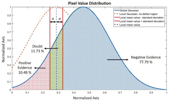
Figure 8.
Schematic representation of D-S belief probability calculations for a random point using its local neighbourhood on the defect-free region on the global distribution of feature matrix (Positive evidence is where there is a defect, negative evidence is where it is non-defective, and doubt is where theere is a high plausibility.) [115].
Another study using the Bayes and D-S methods was recently introduced for multi-material image representation [116]. X-ray computed tomography was applied with various configurations to provide images for different materials of a particular object. This means that the D-S combination rule was implemented to produce a fusion image using three different energy images. Five different attenuation-based hypotheses have been chosen to apply the D-S combination because they give different grey values due to the energy range difference. It has been stated that the proposed method ensured higher image quality for the contrast-to-noise ratio, even though it had several artefacts. The results were also compared with the Bayes combination results, finding that it had a higher risk of conflict. In conclusion, it can be stated that the D-S theory has rarely been used for combination attempts of NDT methods and needs to find more space in NDT application due to its effective usability.
5. Evaluation Strategies and Performance Metrics
Evaluation plays an important part in NDT-based proposed methods towards validation, and it can be classified under quantitative and qualitative approaches. The simplest and most straightforward method is qualitative evaluation (mainly visual), which depends on the experience of the operator performing it. The aerospace industry has gradually moved towards both qualitative and quantitative evaluation, relying less on the operators’ skills and expertise [117]. Noting that NDT inspection is regarded as a quantitative analysis method, many papers in the current literature pay close attention to evaluation (and the use or proposal of relevant evaluation metrics) to support the efficacy of their approaches. We aim to systematise the presentation of evaluation strategies in this section, providing critical insights into NDT image fusion-related efficacy.
A useful example of the importance of evaluation in NDT-based inspection is in a highly noted recent paper [118], which looked into barely visible impact damage (BVID) in composite materials. The authors used NDT fusion of ultrasonic testing and X-ray computed tomography. Their particular fusion approach is shown graphically in Figure 9a, with a particular aim of investigating the true mapping of the defect from UT to the true defect from X-ray CT. (Figure 9b illustrates the scanning views obtained for the defect.) Their particular metric was the distance from the defect’s centre to the boundary points (see the example in Figure 9c, which illustrates a form of pseudo-segmentation of the defect area). The authors included statistical analysis to showcase the differences between the UT C-scans and B-scans relative to the defect mapping (estimation accuracy of the BVID), with the C-scan providing better overall results, as claimed by the authors of the work. An interesting outcome from this paper to consider is the transition from a qualitative aspect of defect analysis (images) to the statistical analysis of the boundary point distance (quantitative) viewpoint.
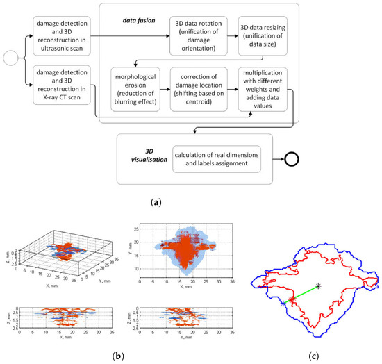
Figure 9.
(a) Katunin-et-al. example fusion approach (block diagram). (b) Detected damage for fusion of X-ray CT scan (red) and UT C-Scan (blue color). (c) Distance calculation of boundary points to the centroid for X-ray CT and UT C-scan [118].
Given that defect analysis, detection and classification can be a very challenging task (depending on the nature and importance of the defect), researchers looked into a variety of evaluation metrics to support NDT analysis. There is no unique evaluation metric that can be applied in this domain (as is the case in many other engineering domains), with a number of evaluation criteria (metrics) introduced to facilitate a more informed outcome decision in NDT analysis of defects [119]. We present a series of important evaluation metrics (merely exhaustive) to assist the readers in understanding their nature, use and potential impact in NDT fusion works.
Common evaluation metrics seen in the literature are the root mean square error (RMSE), signal-to-noise ratio (SNR), correlation coefficient (CC), (fusion) mutual information (MFI) and structural similarity index (SSIM). It is possible to mention more metrics, but many of them are fairly correlated with each other, as can be seen with the 27 different metrics in [120]. Papers refer to these for evaluating the performance of fusion methods. In particular, a recent paper [119] closely utilised these criteria for their work on NDT fusion for defect analysis in Si-PV cells and comparison of the best algorithm outcomes.
We briefly present the nature of the five metrics mentioned above and their expressions, given in Table 8, for an image set for completeness. The image example was obtained from the Northeastern University (NEU) surface defect dataset, which includes six types of surface defects [121]. From the original image, a second version had semi-blurred compressed corruption (pixelisation), and the third version was corrupted by Gaussian distribution noise. Figure 10 shows the three image snapshots, and Figure 11 gives the absolute differences. Blurring and noise have shaded defects at different levels, causing a visible loss of quality. The absolute difference images also indicate the corruption effects, showing how the defects were hidden. After this point, these images will be handled as corrupted and noisy.
Table 8.
Fusion performance evaluation metrics.
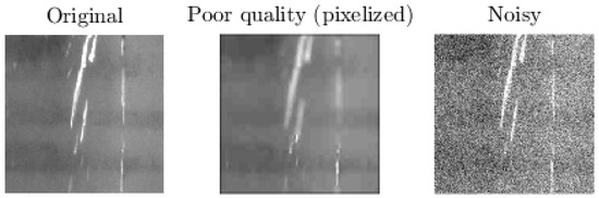
Figure 10.
Original and artificial source images to compare and see the effect of fusion and calculate evaluation metrics over the images from [122].
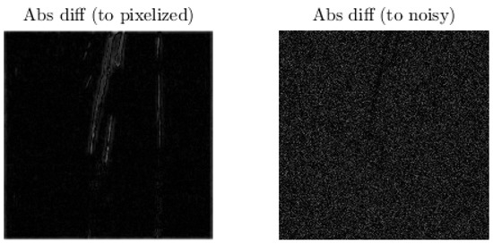
Figure 11.
Absolute difference imagesfor seeing how the corruption affected the images (with respect to original image). Images were converted to grayscale first.
Figure 12 shows the different images in a array format. The bottom-right image is a fused image version of the noisy and corrupted image versions via alpha blending with the (fused) image intensities together as a single dataset. It can clearly be seen that the fused image had a purer texture than the sources in terms of noise and corrupting effects. Here, we will explain the evaluation metrics over these example images using the calculated values between the reference image and sources, including the fused image.
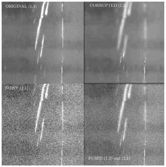
Figure 12.
Montage of images with the fused version of the noisy and corrupted image versions (grayscale).
Root mean square error (RMSE): The RMSE, given the pixel intensity nature of the image, is a measure of the proximity of the two images that are compared. From a statistical viewpoint, the RMSE refers to the standard deviation of the error under investigation. A smaller value for the RMSE indicates closer similarity of the images (in the case of a fused image, the similarity to the original one) [123]. It is noted here that the MSE is closely related to the RMSE. Hence, we do not explain the MSE metric in detail. A useful example, in this case, can be seen in [90], which calculated the MSE and RMSE values for the radius and depth estimations of holes and stated that the bigger gaps between the estimated and expected (real) values might represent an insufficiency of the fusion operation. The authors attributed these high MSE and RMSE values to the blind zone effect of the ultrasonic imaging method for their case. In addition, the authors of [70] agreed that the RMSE is a measurement of detectability, showing that lower values indicated less contrast between the estimations and expectations. Table 9 shows the evaluation values for the example images, including corrupted, noisy and fused examples as a comparison. For our basic example application, it was not surprising to find less difference in the metrics between just the corrupted and original image, although the fused image had a considerably lower RMSE than the noisy image but slightly larger than the corrupted one. Even so, the lower RMSE value of the fused image indicates that the fusion successfully preserved the scratches’ information. On the other hand, thresholding of these images indicated that preprocessing might affect the fusion success, as can be seen from the values of the same metrics. After a basic segmentation by adaptive thresholding, the fused image had the lowest RMSE value, visibly showing the highest similarity.
Table 9.
A comparison of the evaluation metric values for the illustrative example for fusion metrics.
Correlation coefficient (CC): This is an indicator that gives values in the range from −1 to 1, revealing the relationship intensity between the sources and the equivalent fused image. The best match between the fused and original images has the highest correlation value [124]. In our example of fusion application, the correlations of the fused and pixelised images were quite close to each other (Table 9). Similar to the RMSE calculation, we can consider that the corrupting operation does not affect the pixel intensities or the features of the image remarkably. However, the correlation of the fused image to the original image was notably higher than the noisy one, indicating that the fusion managed to merge the valuable components of the sources. Segmentation (thresholding) as a preprocessing step made the fusion result have the highest correlation with the original images eventually.
Fusion mutual information (FMI): This metric, based on the mutual information criterion, evaluates how much of the original images’ features, such as the edge, detail or contrast, are inherited in the fused image [125]. The FMI computes the degree of dependency between the input images and the fused image [126]. Smaller values for the FMI indicate worse quality for the fused image. In our case, the original image features were firmly maintained in the corrupted image, with a notably higher FMI value than those of the noisy and fused ones. That aside, the fused one also had a relatively higher FMI value than the noisy one. The story was different when the intensity became deterministic (black and white segmented areas) in the threshold images (Figure 13). In such a case, the corrupted image had the lowest FMI value, and the fused one had the largest FMI value, confirming the benefit of even a simplified fusion operation.
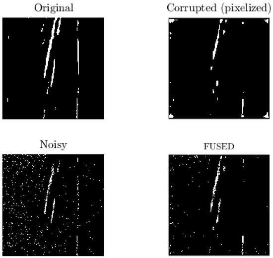
Figure 13.
Simple segmentation via the adaptive threshold of the grayscale images from Figure 12.
Signal-to-noise ratio (SNR): The SNR provides a metric of evaluating the quality of a signal quantitatively when comparing the fused and original signals [127], and it gives the proportion of signal power to noise power:
where denotes the sum of the squares of the signal values for the estimated signal and the difference (error or noise) between the estimated and original signals. With the SNR measuring the ratio between the information and noise of the fused image, a higher value reveals a greater similarity between the fused and reference (original) images. In an example fusion of terahertz and thermal imaging, the larger SNR values contributing to the achievement of suppressing the background noise showed that the salient features were extracted successfully [102]. Another interesting quantitative assessment with the SNR demonstrated that although the fusion provided a higher contrast and resolution, the SNR value of the fused image was relatively lower [99]. This might be attributed to calculating the average SNR from the SNR values of different depths. Another closely relevant metric the peak signal-to-noise ratio (PSNR), indicates the ratio of effective information to noise using the maximum squared signal intensity. The SNR and PSNR values of our example evaluation application indicated that the fused image had the greatest values, demonstrating that a successful fusion can provide more evident marks by reducing the noise effects. This gave the same results after the thresholding application, demonstrating that the SNR and PSNR values were not affected by this preprocessing operation, contrary to other metrics. Moreover, the negative SNR value of the noisy segmented image might be attributed to the noise density of the image being heavier than the signal density [128].
Structural similarity index (SSIM): The SSIM approach compares the luminance (l), contrast (c) and structure (s) in an independent manner using the mean and standard deviation values [129]. This means any change in one does not affect the other parameters:
The application can be performed gradually in a square window which moves pixel by pixel across the image. The local statistics and the SSIM index are computed at each step in the range from 0 to 1. The SSIM is another positive indicator expressing that the higher the values, the greater the correlation. In our example, the corrupted images, as well as the thresholded (segmented) ones, had the highest similarity with the reference image, unsurprisingly. The fused image had a relatively higher similarity to the original image than the noisy one. This means that the fusion managed to compensate for the heavy disturbance effect of the noise partially. An example from the studies above [102] used the SSIM method to determine the defect preservation ability in the defective regions of raw images. The authors emphasised that the higher SSIM values of the proposed training algorithm indicate that it could extract adequate information from the input images.
6. Insights from the Survey and Future Prospects
This review paper presented, in a rigorous way, image fusion and evaluation strategies for NDT, taking into account various structures (albeit with a particular focus towards composites). It is clear that the studies indicate that using image fusion is promising for improving the reliability of inspections. An important highlight from this study is that various image fusion methods which are well-studied in other domains, such as remote sensing and image recognition, have not been extensively applied to NDT yet.
Individual fusion techniques’ performances with regard to a number of evaluation metrics were presented, including insights on how they have been perceived in studies in the literature. These metrics provide a quantitative means of identifying the best fusion approach for the specific or given inspection case. Each method is capable of revealing different aspects. For example, adding small noise to simulate a more realistic environment can significantly impact each technique with defect variability. Current studies have shown that the results depend on the acquisition system (i.e., being multi-sensor or multi-excitation). Different configurations impact the results. Another critical point is the applicability of the fusion method. This can differ depending on the level of fusion or whether it is pixel-wise or region-based. As one moves towards the use of machine learning tools, the importance of having sufficient datasets (of realistic defects) for training and validation is paramount.
The widespread use of high-performance AI (ML)-based fusion approaches in aviation has the potential to improve the reliability and profitability of aviation operations. This review paper sheds further light on utilising the fusion of NDT techniques appropriately in this field. This was shown by the highlights of applying fusion in other domains, which can inform the fusion-based inspection of aeronautical structures (particularly composites). The following points are noted from this rigorous survey study:
- There is no comprehensive review of NDT image fusion (this review paper fills this research gap).
- Fusion applications for composite structures are very limited.
- Low-level (signal or pixel) fusion applications require a precise registration that might be possible to reduce its effect on the higher-level fusion structures.
- General algebraic fusion rules have often been utilised as a main rule in low-level fusion or auxiliary for higher levels.
- PCA and wavelets are the most preferred methods among the current applications, but few relate to AI applications.
- Preprocessing operations before applying fusion are a vital part of the process.
- There is a plethora of evaluation metrics, and a series of these tends to be used in validation studies. This seems to be application-dependent.
- Even though ultrasonics and acoustic emission seem to outshine the other methods in terms of capability for various defect types, each technique has individual characteristics for their sensing ranges.
7. Conclusions
Airworthiness in aviation is vital for the safe operation of and guaranteeing the safety of both passengers and aircrew. In this context, MROs—typically complex processes—in the aerospace industry has strict and precise requirements defined by airworthiness authorities. Enabling more sustainable aviation utilisation of novel materials such as composites, given their potential for weight reduction of structures and attractive material properties, necessitates efficient MROs in order to avoid catastrophic failures. Structural inspection-wise (NDT) approaches are preferable, given their non-destructive testing nature, to ensure structural component integrity and reassure proper function expectations. Characterisation and localisation of possible defects at an early stage is one of the most crucial steps, given that even micro-cracks going unnoticed (and not addressed or treated) can result in catastrophic incidents.
Individual inspection techniques may be limited by their sensing technologies, and fusion provides a potential solution in improved inspection performance and timely information to the inspection expert for efficient MROs. This review paper provided comprehensive insights into the recent progress in image fusion and its potential impact on composite structure inspection, together with a rigorous analysis of the challenges in this new and challenging research field. It was noted in this research that PCA and wavelet decomposition-based fusion approaches seem to be preferred more often compared with learning-based methods. With the advent of AI and ML tools and the accumulation of extended datasets, more learning-based schemes will appear. There are limited examples of fusion-based inspection of composite materials, and the potential of fusion-based inspection in this area to positively impact aerospace MROs is vast, as presented in the discussion of this review paper.
Author Contributions
Conceptualisation, A.Z., N.P.A. and M.E.T.; methodology, M.E.T.; writing—original draft preparation, M.E.T.; writing—review and editing and supervision, A.Z. and N.P.A. All authors have read and agreed to the published version of the manuscript.
Funding
This research received no external funding.
Institutional Review Board Statement
Not applicable.
Informed Consent Statement
Not applicable.
Data Availability Statement
Data sharing not applicable.
Acknowledgments
The first author acknowledges the Republic of Turkey’s Ministry of National Education for supporting his PhD studies.
Conflicts of Interest
The authors declare no conflict of interest.
Abbreviations
The following abbreviations are used in this manuscript:
| AI | Artificial intelligence |
| ANN/CNN | Artificial/convolutional neural network |
| BVID | Barely visible impact damage |
| CC | Correlation coefficient |
| CFRP | Carbon fiber-reinforced polymer |
| CT | Computed tomography |
| D-S | Dempster–Shafer method |
| DWT | Discrete wavelet transform |
| EC | Eddy current |
| FMI | Fusion mutual information |
| GFRP | Glass fiber-reinforced polymer |
| GPR | Ground-penetrating radar |
| IATA | International Air Transport Association |
| MAE | Mean absolute error |
| MRO | Maintenance repair operation |
| NDT/NDI | Non-destructive testing/inspection |
| PCA | Principal component analysis |
| RMSE | Root mean square error |
| SD | Standard deviation |
| SHM | Structural health monitoring |
| SNR | Signal-to-noise ratio |
| SSIM | Structural similarity index |
| TLU | Threshold logic unit |
| UT | Ultrasonic testing |
References
- Vieira, D.R.; Loures, P.L. Maintenance, repair and overhaul (MRO) fundamentals and strategies: An aeronautical industry overview. Int. J. Comput. Appl. 2016, 135, 21–29. [Google Scholar]
- Sahay, A. 1—An overview of aircraft maintenance. In Leveraging Information Technology for Optimal Aircraft Maintenance, Repair and Overhaul (MRO); Sahay, A., Ed.; Woodhead Publishing: Sawston, UK, 2012; pp. 1–230. [Google Scholar] [CrossRef]
- Anon. Inmarsat Report: The Aircraft-Connectivity and Consciousness. 2022. Available online: https://www.inmarsat.com/en/insights/aviation/2022/future-aviation-connectivity.html (accessed on 9 December 2022).
- Büchter, K.D.; Sebastia Saez, C.; Steinweg, D. Modeling of an aircraft structural health monitoring sensor network for operational impact assessment. Struct. Health Monit. 2022, 21, 208–224. [Google Scholar] [CrossRef]
- Bates, D.; Smith, G.; Lu, D.; Hewitt, J. Rapid thermal non-destructive testing of aircraft components. Compos. Part B Eng. 2000, 31, 175–185. [Google Scholar] [CrossRef]
- Towsyfyan, H.; Biguri, A.; Boardman, R.; Blumensath, T. Successes and challenges in non-destructive testing of aircraft composite structures. Chin. J. Aeronaut. 2020, 33, 771–791. [Google Scholar] [CrossRef]
- Anonymous. Air Industry Faces Summer Chaos. Aerosp.-R. Aeronaut. Soc. 2022, 10–11. [Google Scholar]
- Ullmann, T.; Schmidt, T.; Hoffmann, S.; Jemmali, R. In-line quality assurance for the manufacturing of carbon fiber reinforced aircraft structures. In Proceedings of the 2nd International Symposium on NDT in Aerospace 2010, Williamsburg, VA, USA, 5–7 October 2010; Volume 124. [Google Scholar]
- Soutis, C. Fibre reinforced composites in aircraft construction. Prog. Aerosp. Sci. 2005, 41, 143–151. [Google Scholar] [CrossRef]
- Braga, D.F.; Tavares, S.; Da Silva, L.F.; Moreira, P.; De Castro, P.M. Advanced design for lightweight structures: Review and prospects. Prog. Aerosp. Sci. 2014, 69, 29–39. [Google Scholar] [CrossRef]
- Giurgiutiu, V. Structural health monitoring (SHM) of aerospace composites. In Polymer Composites in the Aerospace Industry; Elsevier: Kidlington, UK, 2020; pp. 491–558. [Google Scholar]
- Cantero-Chinchilla, S.; Chiachío, J.; Chiachío, M.; Chronopoulos, D.; Jones, A. A robust Bayesian methodology for damage localization in plate-like structures using ultrasonic guided-waves. Mech. Syst. Signal Process. 2019, 122, 192–205. [Google Scholar] [CrossRef]
- Brethee, K.F.; Uwayed, A.N.; Alden Qwam, A.Y. A novel index for vibration-based damage detection technique in laminated composite plates under forced vibrations: Experimental study. Struct. Health Monit. 2023, 14759217221145622. [Google Scholar] [CrossRef]
- Balasubramaniam, K.; Sikdar, S.; Ziaja, D.; Jurek, M.; Soman, R.; Malinowski, P.M. A global-local damage localization and quantification approach in composite structures using ultrasonic guided waves and active infrared thermography. Smart Mater. Struct. 2023, 32, 035016. [Google Scholar] [CrossRef]
- Ni, T.; Guo, B.; Yang, C. Design of Ultrasonic Testing System for Defects of Composite Material Bonding Structure Based on Deep Learning Technology. In Proceedings of the 2020 International Conference on Virtual Reality and Intelligent Systems (ICVRIS), Zhangjiajie, China, 18–19 July 2021; pp. 263–266. [Google Scholar] [CrossRef]
- Jolly, M.; Prabhakar, A.; Sturzu, B.; Hollstein, K.; Singh, R.; Thomas, S.; Foote, P.; Shaw, A. Review of Non-destructive Testing (NDT) Techniques and their Applicability to Thick Walled Composites. Procedia CIRP 2015, 38, 129–136. [Google Scholar] [CrossRef]
- Heslehurst, R.B. Defects and Damage in Composite Materials and Structures; CRC Press: Boca Raton, FL, USA, 2014. [Google Scholar] [CrossRef]
- Balageas, D.; Maldague, X.; Burleigh, D.; Vavilov, V.; Oswald-Tranta, B.; Roche, J.M.; Pradere, C.; Carlomagno, G. Thermal (IR) and other NDT techniques for improved material inspection. J. Nondestruct. Eval. 2016, 35, 18. [Google Scholar] [CrossRef]
- Yu, Y.; Zhang, R.; Lu, L.; Yang, Y. The bimodal neutron and x-ray imaging driven by a single electron linear accelerator. Appl. Sci. 2021, 11, 6050. [Google Scholar] [CrossRef]
- Wang, J.; Xu, T.; Zhang, L.; Chang, T.; Zhang, J.; Yan, S.; Cui, H.L. Nondestructive damage evaluation of composites based on terahertz and X-ray image fusion. NDT E Int. 2022, 127, 102616. [Google Scholar] [CrossRef]
- De Oliveira, B.C.; Marció, B.S.; Flesch, R.C. Enhanced damage measurement in a metal specimen through the image fusion of tone-burst vibro-acoustography and pulse-echo ultrasound data. Meas. J. Int. Meas. Confed. 2021, 167, 108445. [Google Scholar] [CrossRef]
- Mohammadkhani, R.; Zanotti Fragonara, L.; Padiyar M, J.; Petrunin, I.; Raposo, J.; Tsourdos, A.; Gray, I. Improving depth resolution of ultrasonic phased array imaging to inspect aerospace composite structures. Sensors 2020, 20, 559. [Google Scholar] [CrossRef]
- Liu, H.; Li, W.; Yang, L.; Deng, K.; Zhao, Y. Automatic reconstruction of irregular shape defects in pulsed thermography using deep learning neural network. Neural Comput. Appl. 2022, 34, 21701–21714. [Google Scholar] [CrossRef]
- Diogo, A.R.; Moreira, B.; Gouveia, C.A.J.; Tavares, J.M.R.S. A Review of Signal Processing Techniques for Ultrasonic Guided Wave Testing. Metals 2022, 12, 936. [Google Scholar] [CrossRef]
- E. Farag, H.; Toyserkani, E.; Khamesee, M.B. Non-Destructive Testing Using Eddy Current Sensors for Defect Detection in Additively Manufactured Titanium and Stainless-Steel Parts. Sensors 2022, 22, 5440. [Google Scholar] [CrossRef]
- Xie, H.; Fang, H.; Li, X.; Wan, L.; Wu, P.; Yu, Y. Low-velocity impact damage detection and characterization in composite sandwich panels using infrared thermography. Compos. Struct. 2021, 269, 114008. [Google Scholar] [CrossRef]
- Avdelidis, N.; Gan, T.H.; Ibarra-Castanedo, C.; Maldague, X. Infrared thermography as a nondestructive tool for materials characterisation and assessment. In Proceedings of the Thermosense: Thermal Infrared Applications XXXIII, Orlando, FL, USA, 26–28 April 2011; Volume 8013, pp. 308–314. [Google Scholar]
- Gupta, M.; Khan, M.A.; Butola, R.; Singari, R.M. Advances in applications of Non-Destructive Testing (NDT): A review. Adv. Mater. Process. Technol. 2021, 8, 2286–2307. [Google Scholar] [CrossRef]
- Cawley, P. Non-destructive testing—current capabilities and future directions. Proc. Inst. Mech. Eng. Part L J. Mater. Des. Appl. 2001, 215, 213–223. [Google Scholar]
- Shahidan, S.; Pulin, R.; Bunnori, N.M.; Holford, K.M. Damage classification in reinforced concrete beam by acoustic emission signal analysis. Constr. Build. Mater. 2013, 45, 78–86. [Google Scholar] [CrossRef]
- AlShorman, O.; Alkahatni, F.; Masadeh, M.; Irfan, M.; Glowacz, A.; Althobiani, F.; Kozik, J.; Glowacz, W. Sounds and acoustic emission-based early fault diagnosis of induction motor: A review study. Adv. Mech. Eng. 2021, 13, 1687814021996915. [Google Scholar] [CrossRef]
- Petrou, M.M.; Petrou, C. Introduction. In Image Processing: The Fundamentals; John Wiley & Sons, Ltd.: Chichester, UK, 2010; Chapter 1; pp. 1–46. [Google Scholar] [CrossRef]
- Sun, H.; Wang, S.; Hu, X.; Liu, H.; Zhou, X.; Huang, J.; Cheng, X.; Sun, F.; Liu, Y.; Liu, D. Detection of surface defects and subsurface defects of polished optics with multisensor image fusion. PhotoniX 2022, 3, 6. [Google Scholar] [CrossRef]
- Omar, Z.; Stathaki, T. Image fusion: An overview. In Proceedings of the 2014 5th International Conference on Intelligent Systems, Modelling and Simulation, Langkawi, Malaysia, 27–29 January 2014; pp. 306–310. [Google Scholar]
- Raol, J.R. Multi-Sensor Data Fusion with MATLAB, 1st ed.; CRC Press, Inc.: Boca Raton, FL, USA, 2009. [Google Scholar]
- Nsengiyumva, W.; Zhong, S.; Lin, J.; Zhang, Q.; Zhong, J.; Huang, Y. Advances, limitations and prospects of nondestructive testing and evaluation of thick composites and sandwich structures: A state-of-the-art review. Compos. Struct. 2021, 256, 112951. [Google Scholar] [CrossRef]
- Tian, Y.P.; Zhou, K.Y.; Feng, X.; Yu, S.L.; Liang, H.; Liang, B. Image fusion for infrared thermography and inspection of pressure vessel. J. Press. Vessel Technol. Trans. ASME 2009, 131, 021502. [Google Scholar] [CrossRef]
- Hill, D.L.; Batchelor, P.G.; Holden, M.; Hawkes, D.J. Medical image registration. Phys. Med. Biol. 2001, 46, R1. [Google Scholar] [CrossRef]
- Oliveira, F.P.; Tavares, J.M.R. Medical image registration: A review. Comput. Methods Biomech. Biomed. Eng. 2014, 17, 73–93. [Google Scholar] [CrossRef]
- Paul, S.; Pati, U.C. A comprehensive review on remote sensing image registration. Int. J. Remote Sens. 2021, 42, 5396–5432. [Google Scholar] [CrossRef]
- Fu, Y.; Lei, Y.; Wang, T.; Curran, W.J.; Liu, T.; Yang, X. Deep learning in medical image registration: A review. Phys. Med. Biol. 2020, 65, 20TR01. [Google Scholar] [CrossRef] [PubMed]
- Meher, B.; Agrawal, S.; Panda, R.; Abraham, A. A survey on region based image fusion methods. Inf. Fusion 2019, 48, 119–132. [Google Scholar] [CrossRef]
- Bloxham, H.A.; Velichko, A.; Wilcox, P.D. Combining Simulated and Experimental Data to Simulate Ultrasonic Array Data From Defects in Materials With High Structural Noise. IEEE Trans. Ultrason. Ferroelectr. Freq. Control 2016, 63, 2198–2206. [Google Scholar] [CrossRef] [PubMed]
- Gong, S.; Liu, C.; Ji, Y.; Zhong, B.; Li, Y.; Dong, H. Advanced Image and Video Processing Using MATLAB; Springer International Publishing: Cham, Switzerland, 2019. [Google Scholar] [CrossRef]
- Murali, K.; Reddy, D.R.K.; Mulaveesala, R. Application of image fusion for the IR images in frequency modulated thermal wave imaging for Non Destructive Testing (NDT). Mater. Today Proc. 2018, 5, 544–549. [Google Scholar] [CrossRef]
- Zhang, J.; Lu, S.; Chen, J. Application of Pseudo-color Image Feature-Level Fusion in Nondestructive Testing of Wire Ropes. J. Fail. Anal. Prev. 2020, 20, 1541–1553. [Google Scholar] [CrossRef]
- Heideklang, R.; Shokouhi, P. Decision-level fusion of spatially scattered multi-modal data for nondestructive inspection of surface defects. Sensors 2016, 16, 105. [Google Scholar] [CrossRef]
- Maierhofer, C.; Zacher, G.; Kohl, C.; Wöstmann, J. Evaluation of radar and complementary echo methods for NDT of concrete elements. J. Nondestruct. Eval. 2008, 27, 47–57. [Google Scholar] [CrossRef]
- Heideklang, R.; Shokouhi, P. Fusion of multi-sensory NDT data for reliable detection of surface cracks: Signal-level vs. decision-level. AIP Conf. Proc. 2016, 1706, 180004. [Google Scholar] [CrossRef]
- Krämer, P.; Weckenmann, A. Multi-energy image stack fusion in computed tomography. Meas. Sci. Technol. 2010, 21, 0451050. [Google Scholar] [CrossRef]
- Helmerich, R.; Niederleithinger, E.; Wiggenhauser, H. Toolbox with nondestructive testing methods for condition assessment of railway bridges. Transp. Res. Rec. 2006, 1943, 65–73. [Google Scholar] [CrossRef]
- Bianchini Ciampoli, L.; Gagliardi, V.; Clementini, C.; Latini, D.; Del Frate, F.; Benedetto, A. Transport Infrastructure Monitoring by InSAR and GPR Data Fusion. Surv. Geophys. 2020, 41, 371–394. [Google Scholar] [CrossRef]
- Zhang, J.; Wang, S. Nondestructive Testing of Wire Ropes Based on Image Fusion of Leakage Flux and Visible Light. J. Fail. Anal. Prev. 2019, 19, 551–560. [Google Scholar] [CrossRef]
- Elshafiey, I.; Algarni, A.; Alkanhal, M.A. Image fusion based enhancement of nondestructive evaluation systems. In Image Fusion; IntechOpen: London, UK, 2011; pp. 211–236. [Google Scholar]
- Metwalli, M.R.; Nasr, A.H.; Farag Allah, O.S.; El-Rabaie, S. Image fusion based on principal component analysis and high-pass filter. In Proceedings of the 2009 International Conference on Computer Engineering and Systems, ICCES’09, Cairo, Egypt, 14–16 December 2009; pp. 63–70. [Google Scholar] [CrossRef]
- Jolliffe, I. Principal Component Analysis; Springer Series in Statistics; Springer: New York, NY, USA, 2002. [Google Scholar]
- Karamizadeh, S.; Abdullah, S.M.; Manaf, A.A.; Zamani, M.; Hooman, A. An Overview of Principal Component Analysis. J. Signal Inf. Process. 2013, 04, 173–175. [Google Scholar] [CrossRef]
- Hasan, B.M.S.; Abdulazeez, A.M. A review of principal component analysis algorithm for dimensionality reduction. J. Soft Comput. Data Min. 2021, 2, 20–30. [Google Scholar]
- Báscones, D.; González, C.; Mozos, D. Hyperspectral image compression using vector quantization, PCA and JPEG2000. Remote Sens. 2018, 10, 907. [Google Scholar] [CrossRef]
- Yang, L.; Xu, Z. Feature extraction by PCA and diagnosis of breast tumors using SVM with DE-based parameter tuning. Int. J. Mach. Learn. Cybern. 2019, 10, 591–601. [Google Scholar] [CrossRef]
- Huang, J.; Wei, Q.; Zhuo, L.; Zhu, J.; Li, C.; Wang, Z. Detection and quantification of artificial delaminations in CFRP composites using ultrasonic thermography. Infrared Phys. Technol. 2023, 130, 104579. [Google Scholar] [CrossRef]
- Ibarra-Castanedo, C.; Piau, J.M.; Guilbert, S.; Avdelidis, N.P.; Genest, M.; Bendada, A.; Maldague, X.P. Comparative study of active thermography techniques for the nondestructive evaluation of honeycomb structures. Res. Nondestruct. Eval. 2009, 20, 1–31. [Google Scholar] [CrossRef]
- Lv, G.; Guo, S.; Chen, D.; Feng, H.; Zhang, K.; Liu, Y.; Feng, W. Laser ultrasonics and machine learning for automatic defect detection in metallic components. NDT E Int. 2023, 133, 102752. [Google Scholar] [CrossRef]
- Yousefi, B.; Sfarra, S.; Castanedo, C.I.; Maldague, X.P. Comparative analysis on thermal non-destructive testing imagery applying Candid Covariance-Free Incremental Principal Component Thermography (CCIPCT). Infrared Phys. Technol. 2017, 85, 163–169. [Google Scholar] [CrossRef]
- Rajic, N. Principal component thermography for flaw contrast enhancement and flaw depth characterisation in composite structures. Compos. Struct. 2002, 58, 521–528. [Google Scholar] [CrossRef]
- Shrestha, R.; Kim, W. Non-destructive testing and evaluation of materials using active thermography and enhancement of signal to noise ratio through data fusion. Infrared Phys. Technol. 2018, 94, 78–84. [Google Scholar] [CrossRef]
- Wei, Y.; Ye, Y.; He, H.; Su, Z.; Ding, L.; Zhang, D. Multi-frequency Fused Lock-in Thermography in Detecting Defects at Different Depths. J. Nondestruct. Eval. 2022, 41, 60. [Google Scholar] [CrossRef]
- Zhu, P.; Cheng, Y.; Bai, L.; Tian, L. Local sparseness and image fusion for defect inspection in eddy current pulsed thermography. IEEE Sensors J. 2019, 19, 1471–1477. [Google Scholar] [CrossRef]
- Zhou, Y.; Mayyas, A.; Omar, M.A. Principal component analysis-based image fusion routine with application to automotive stamping split detection. Res. Nondestruct. Eval. 2011, 22, 76–91. [Google Scholar] [CrossRef]
- Lee, S.; Chung, Y.; Kim, C.; Shrestha, R.; Kim, W. Thermographic Inspection of CLP Defects on the Subsurface Based on Binary Image. Int. J. Precis. Eng. Manuf. 2022, 23, 269–279. [Google Scholar] [CrossRef]
- Proakis, J.G. Digital Signal Processing Principles, Algorithms, and Applications, 3rd ed.; Prentice-Hall, Inc.: Upper Saddle River, NJ, USA, 1996. [Google Scholar]
- Leach, W.; Lum, J.; Champley, K.; Azevedo, S.; Gardner, C.; Kim, H.; Stobbe, D.; Townsend, A.; Tringe, J.W. Fourier method for 3-dimensional data fusion of X-ray Computed Tomography and ultrasound. NDT E Int. 2022, 127, 102600. [Google Scholar] [CrossRef]
- Shi, W.; Zhu, C.Q.; Tian, Y.; Nichol, J. Wavelet-based image fusion and quality assessment. Int. J. Appl. Earth Obs. Geoinf. 2005, 6, 241–251. [Google Scholar] [CrossRef]
- Zhou, Y.; Yu, L.; Zhi, C.; Huang, C.; Wang, S.; Zhu, M.; Ke, Z.; Gao, Z.; Zhang, Y.; Fu, S. A Survey of Multi-Focus Image Fusion Methods. Appl. Sci. 2022, 12, 6281. [Google Scholar] [CrossRef]
- Patel, K. Fusion Algorithms for Images Based on Principal Component Analysis and Discrete Wavelet Transform. Int. J. Innov. Res. Sci. Technol. 2015, 1, 180–182. [Google Scholar]
- Balakrishnan, S.; Cacciola, M.; Udpa, L.; Purnachandra Rao, B.; Jayakumar, T.; Raj, B. Development of image fusion methodology using discrete wavelet transform for eddy current images. NDT E Int. 2012, 51, 51–57. [Google Scholar] [CrossRef]
- Daryabor, P.; Safizadeh, M. Image fusion of ultrasonic and thermographic inspection of carbon/epoxy patches bonded to an aluminum plate. Ndt E Int. 2017, 90, 1–10. [Google Scholar] [CrossRef]
- Zhang, X.W.; Liang, R.Y.; Lv, Y.Y. Research on multi-sensor information fusion for the detection of surface defects in copper strip. In Proceedings of the 2009 International Conference on Computational Intelligence and Software Engineering, CiSE 2009, Wuhan, China, 11–13 December 2009. [Google Scholar] [CrossRef]
- Muduli, P.R.; Pati, U.C. A novel technique for wall crack detection using image fusion. In Proceedings of the 2013 International Conference on Computer Communication and Informatics, ICCCI 2013, Coimbatore, India, 4–6 January 2013; pp. 1–6. [Google Scholar] [CrossRef]
- Mehdinia, S.; Schumacher, T.; Song, X.; Wan, E. A pipeline for enhanced multimodal 2D imaging of concrete structures. Mater. Struct. Et Constr. 2021, 54, 228. [Google Scholar] [CrossRef]
- Li, X.; Liu, Z.; Jiang, X.; Lodewijks, G. Method for detecting damage in carbon-fibre reinforced plastic-steel structures based on eddy current pulsed thermography. Nondestruct. Test. Eval. 2018, 33, 1–19. [Google Scholar] [CrossRef]
- Gros, X.E.; Liu, Z.; Tsukada, K.; Hanasaki, K. Experimenting with pixel-level NDT data fusion techniques. IEEE Trans. Instrum. Meas. 2000, 49, 1083–1090. [Google Scholar] [CrossRef]
- Deng, W.; Matuszewski, B.; Shark, L.; Smith, J.; Cavaccini, G. Multi-modality NDT image fusion and its mapping on curved 3D CAD surface. In Proceedings of the 16th World Conference on NDT, Montreal, QC, Canada, 30 August–3 September 2004. [Google Scholar]
- Heideklang, R.; Shokouhi, P. Multi-sensor image fusion at signal level for improved near-surface crack detection. NDT E Int. 2015, 71, 16–22. [Google Scholar] [CrossRef]
- Wang, Q.; Zhou, H.; Xia, R.; Liu, Q.; Zhao, B.Y. Time Segmented Image Fusion Based Multi-Depth Defects Imaging Method in Composites With Pulsed Terahertz. IEEE Access 2020, 8, 155529–155537. [Google Scholar] [CrossRef]
- Abiodun, O.I.; Jantan, A.; Omolara, A.E.; Dada, K.V.; Mohamed, N.A.E.; Arshad, H. State-of-the-art in artificial neural network applications: A survey. Heliyon 2018, 4, e00938. [Google Scholar] [CrossRef]
- Millidere, M.; Gomec, F.S.; Kurt, H.B.; Akgul, F. Multi-Fidelity Aerodynamic Dataset Generation of a Fighter Aircraft with a Deep Neural-Genetic Network. In Proceedings of the AIAA AVIATION 2021 FORUM, Virtual, 2–6 August 2021; p. 3007. [Google Scholar]
- Gurney, K. An Introduction to Neural Networks; Taylor & Francis, Inc.: London, UK, 1997. [Google Scholar]
- Shin, H.; Rüttgers, M.; Lee, S. Neural Networks for Improving Wind Power Efficiency: A Review. Fluids 2022, 7, 367. [Google Scholar] [CrossRef]
- Cormerais, R.; Duclos, A.; Wasselynck, G.; Berthiau, G.; Longo, R. A data fusion method for non-destructive testing by means of artificial neural networks. Sensors 2021, 21, 2598. [Google Scholar] [CrossRef]
- Hu, J.; Zhang, H.; Sfarra, S.; Perilli, S.; Sergi, C.; Sarasini, F.; Maldague, X. Multi-Excitation Infrared Fusion for Impact Evaluation of Aluminium-BFRP/GFRP Hybrid Composites. Sensors 2021, 21, 5961. [Google Scholar] [CrossRef] [PubMed]
- Krizhevsky, A.; Sutskever, I.; Hinton, G.E. ImageNet Classification with Deep Convolutional Neural Networks. In Advances in Neural Information Processing Systems; Pereira, F., Burges, C., Bottou, L., Weinberger, K., Eds.; Curran Associates, Inc.: Red Hook, NY, USA, 2012; Volume 25. [Google Scholar]
- Ronneberger, O.; Fischer, P.; Brox, T. U-Net: Convolutional Networks for Biomedical Image Segmentation. In Medical Image Computing and Computer-Assisted Intervention—MICCAI 2015; Navab, N., Hornegger, J., Wells, W.M., Frangi, A.F., Eds.; Springer International Publishing: Cham, Switzerland, 2015; pp. 234–241. [Google Scholar]
- He, K.; Zhang, X.; Ren, S.; Sun, J. Deep Residual Learning for Image Recognition. In Proceedings of the Proceedings of the IEEE Conference on Computer Vision and Pattern Recognition (CVPR), Las Vegas, NV, USA, 27–30 June 2016. [Google Scholar]
- Huang, G.; Liu, Z.; van der Maaten, L.; Weinberger, K.Q. Densely Connected Convolutional Networks. In Proceedings of the IEEE Conference on Computer Vision and Pattern Recognition, Honolulu, HI, USA, 21–26 July 2017. [Google Scholar] [CrossRef]
- Szegedy, C.; Liu, W.; Jia, Y.; Sermanet, P.; Reed, S.; Anguelov, D.; Erhan, D.; Vanhoucke, V.; Rabinovich, A. Going Deeper with Convolutions. In Proceedings of the IEEE Conference on Computer Vision and Pattern Recognition, Boston, MA, USA, 7–12 June 2015. [Google Scholar] [CrossRef]
- Lu, S.; Zhang, J. Quantitative Nondestructive Testing of Wire Ropes Based on Features Fusion of Magnetic Image and Infrared Image. Shock Vib. 2019, 2019, 2041401. [Google Scholar] [CrossRef]
- Jing, L.; Wang, T.; Zhao, M.; Wang, P. An adaptive multi-sensor data fusion method based on deep convolutional neural networks for fault diagnosis of planetary gearbox. Sensors 2017, 17, 414. [Google Scholar] [CrossRef]
- Hu, J.; Zhang, H.; Sfarra, S.; Santulli, C.; Tian, G.; Maldague, X. Novel infrared-terahertz fusion 3D non-invasive imaging of plant fibre-reinforced polymer composites. Compos. Sci. Technol. 2022, 226, 109526. [Google Scholar] [CrossRef]
- Fu, G.; Jia, S.; Zhu, W.; Yang, J.; Cao, Y.; Yang, M.Y.; Cao, Y. Fusion of multi-light source illuminated images for effective defect inspection on highly reflective surfaces. Mech. Syst. Signal Process. 2022, 175, 109109. [Google Scholar] [CrossRef]
- Hu, J.; Zhang, H.; Sfarra, S.; Gargiulo, G.; Avdelidis, N.P.; Zhang, M.; Yang, D.; Maldague, X. Non-destructive imaging of marqueteries based on a new infrared-terahertz fusion technique. Infrared Phys. Technol. 2022, 125, 104277. [Google Scholar] [CrossRef]
- Hu, J.; Zhang, H.; Sfarra, S.; Pivarčiová, E.; Yao, Y.; Duan, Y.; Ibarra-Castanedo, C.; Tian, G.; Maldague, X. Autonomous dynamic line-scan continuous-wave terahertz non-destructive inspection system combined with unsupervised exposure fusion. NDT E Int. 2022, 132, 102705. [Google Scholar] [CrossRef]
- Dubois, D.; Ostasiewicz, W.; Prade, H. Fuzzy Sets: History and Basic Notions. In Fundamentals of Fuzzy Sets; Dubois, D., Prade, H., Eds.; Springer: Boston, MA, USA, 2000; pp. 21–124. [Google Scholar] [CrossRef]
- Kambalimath, S.; Deka, P.C. A basic review of fuzzy logic applications in hydrology and water resources. Appl. Water Sci. 2020, 10, 191. [Google Scholar] [CrossRef]
- Völker, C.; Shokouhi, P. Clustering based multi sensor data fusion for honeycomb detection in concrete. J. Nondestruct. Eval. 2015, 34, 32. [Google Scholar] [CrossRef]
- Hall, I.D.; McNab, A.; Hayward, G. Improved ultrasonic image generation through tomographic image fusion. Ultrasonics 1999, 37, 433–443. [Google Scholar] [CrossRef]
- Santos, T.; Vilaça, P.; Quintino, L. Developments in NDT for detecting imperfections in friction stir welds in aluminium alloys. Riv. Ital. Della Saldatura 2009, 61, 65–72. [Google Scholar] [CrossRef]
- Ploix, M.A.; Garnier, V.; Breysse, D.; Moysan, J. NDE data fusion to improve the evaluation of concrete structures. NDT E Int. 2011, 44, 442–448. [Google Scholar] [CrossRef]
- Habibalahi, A.; Safizadeh, M. Pulsed eddy current and ultrasonic data fusion applied to stress measurement. Meas. Sci. Technol. 2014, 25, 055601. [Google Scholar] [CrossRef]
- Cotič, P.; Jagličić, Z.; Niederleithinger, E.; Stoppel, M.; Bosiljkov, V. Image fusion for improved detection of near-surface defects in NDT-CE using unsupervised clustering methods. J. Nondestruct. Eval. 2014, 33, 384–397. [Google Scholar] [CrossRef]
- Challa, S.; Koks, D. Bayesian and dempster-shafer fusion. Sadhana 2004, 29, 145–174. [Google Scholar] [CrossRef]
- Chang, Q.; Zhao, H. Two-dimensional beam focusing impact localization based on probabilistic tomography fusion. Mech. Syst. Signal Process. 2022, 177, 109200. [Google Scholar] [CrossRef]
- Nsengiyumva, W.; Zhong, S.; Luo, M.; Zhang, Q.; Lin, J. Critical insights into the state-of-the-art NDE data fusion techniques for the inspection of structural systems. Struct. Control Health Monit. 2022, 29, e2857. [Google Scholar] [CrossRef]
- Prachetaa, R.; Rao, B. Image processing for NDT images. In Proceedings of the 2010 International Conference on Signal and Image Processing, Chennai, India, 15–17 December 2010; pp. 169–174. [Google Scholar]
- Yilmaz, B.; Ba, A.; Jasiuniene, E.; Bui, H.K.; Berthiau, G. Evaluation of bonding quality with advanced nondestructive testing (Ndt) and data fusion. Sensors 2020, 20, 5127. [Google Scholar] [CrossRef]
- Oujebbour, F.Z.; Doudet, V.K. Image Fusion Based on Evidence Theory for Multi-Energy X-Ray Computed Tomography. J. Nondestruct. Eval. 2022, 41, 53. [Google Scholar] [CrossRef]
- Ibarra-Castanedo, C.; Genest, M.; Servais, P.; Maldague, X.P.V.; Bendada, A. Qualitative and quantitative assessment of aerospace structures by pulsed thermography. Nondestruct. Test. Eval. 2007, 22, 199–215. [Google Scholar] [CrossRef]
- Katunin, A.; Wronkowicz-Katunin, A.; Dragan, K. Impact Damage Evaluation in Composite Structures Based on Fusion of Results of Ultrasonic Testing and X-ray Computed Tomography. Sensors 2020, 20, 1867. [Google Scholar] [CrossRef] [PubMed]
- Yang, R.; Du, B.; Duan, P.; He, Y.; Wang, H.; He, Y.; Zhang, K. Electromagnetic Induction Heating and Image Fusion of Silicon Photovoltaic Cell Electrothermography and Electroluminescence. IEEE Trans. Ind. Inform. 2020, 16, 4413–4422. [Google Scholar] [CrossRef]
- Li, S.; Li, Z.; Gong, J. Multivariate statistical analysis of measures for assessing the quality of image fusion. Int. J. Image Data Fusion 2010, 1, 47–66. [Google Scholar] [CrossRef]
- Song, K.; Yan, Y. A noise robust method based on completed local binary patterns for hot-rolled steel strip surface defects. Appl. Surf. Sci. 2013, 285, 858–864. [Google Scholar] [CrossRef]
- Benbarrad, T.; Eloutouate, L.; Arioua, M.; Elouaai, F.; Laanaoui, M.D. Impact of Image Compression on the Performance of Steel Surface Defect Classification with a CNN. J. Sens. Actuator Netw. 2021, 10, 73. [Google Scholar] [CrossRef]
- Nadipally, M. Chapter 2—Optimization of Methods for Image-Texture Segmentation Using Ant Colony Optimization. In Intelligent Data Analysis for Biomedical Applications; Hemanth, D.J., Gupta, D., Emilia Balas, V., Eds.; Intelligent Data-Centric Systems; Academic Press: London, UK, 2019; pp. 21–47. [Google Scholar] [CrossRef]
- Klonus, S.; Ehlers, M. Performance of evaluation methods in image fusion. In Proceedings of the 2009 12th International Conference on Information Fusion, Seattle, WA, USA, 6–9 July 2009; pp. 1409–1416. [Google Scholar]
- Zhou, J.; Ren, K.; Wan, M.; Cheng, B.; Gu, G.; Chen, Q. An Infrared and Visible Image Fusion Method Based on VGG-19 Network. Optik 2021, 248, 168084. [Google Scholar] [CrossRef]
- Jagalingam, P.; Hegde, A.V. A Review of Quality Metrics for Fused Image. Aquat. Procedia 2015, 4, 133–142. [Google Scholar] [CrossRef]
- Wang, Q.; Shen, Y.; Jin, J. Performance evaluation of image fusion techniques. Image Fusion Algorithms Appl. 2008, 19, 469–492. [Google Scholar]
- Petrovi, V.; Xydeas, C. On the effects of sensor noise in pixel-level image fusion performance. In Proceedings of the Third International Conference on Information Fusion, Paris, France, 10–13 July 2000; Volume 2. [Google Scholar]
- Wang, Z.; Bovik, A.; Sheikh, H.; Simoncelli, E. Image quality assessment: From error visibility to structural similarity. IEEE Trans. Image Process. 2004, 13, 600–612. [Google Scholar] [CrossRef]
Disclaimer/Publisher’s Note: The statements, opinions and data contained in all publications are solely those of the individual author(s) and contributor(s) and not of MDPI and/or the editor(s). MDPI and/or the editor(s) disclaim responsibility for any injury to people or property resulting from any ideas, methods, instructions or products referred to in the content. |
© 2023 by the authors. Licensee MDPI, Basel, Switzerland. This article is an open access article distributed under the terms and conditions of the Creative Commons Attribution (CC BY) license (https://creativecommons.org/licenses/by/4.0/).