Abstract
Evaluation of the impact of new static-pressure pile penetration on used piles is vitally important for the reutilization of the used piles. The cavity expansion theory in semi-infinite soil is adopted to obtain the displacement field of the surrounding soil caused by new pile penetration, and then the displacement is applied to the used pile based on a two-stage method to analyze the deformation and internal force of the used pile. The effects of constraint conditions of the used pile, the pile rigidity and the soil modulus on the response of the used pile are considered. Meanwhile, numerical analysis is adopted to verify the effectiveness of the theoretical method. The influence of the distance between the new and used piles and the radius of the new pile is analyzed, and the measures to reduce the influence of new pile penetration on existing piles are proposed. The results show that the form of pile end only affects the deformation near the pile end. With the increase in pile diameter, the existing pile deformation gradually increases. As the distance between the existing pile and new pile increases, the existing pile deformation decreases significantly.
1. Introduction
After the demolition of old buildings, a large number of pile foundations are left at the site. Treatment of the used piles has become an urgent problem in today’s urban renovation projects and the renewal of industrial buildings [1]. Uprooting and discarding the used piles will generate a large amount of energy consumption and cause a huge waste of resources, while leaving them at the site will seriously threaten the safety of new projects (e.g., the existence of old piles hinders the construction of new foundations). Reusing the used piles after evaluating the bearing capacity of them combined with newly driven piles to form the foundation of new buildings is an effective treatment [2,3]. However, the soil squeezing effect of new pile penetration will cause additional internal force and deformation of the adjacent used piles, which will affect their bearing performance. Therefore, it is important to evaluate the impact of new pile penetration on the used piles and put forward corresponding protective measures.
Scholars have carried out a large amount of research on the soil squeezing effect of pile penetration, including theoretical analysis, testing and numerical simulation. Sagaseta et al. [4,5] adopted the source–sink method and the cavity expansion method to calculate the displacement field of the surrounding soil due to pile penetration, considering the influence of the free surface boundary. Subsequently, the cavity expansion method was proved to be accurate enough to simulate the process of static pile penetration. Many scholars have developed the cavity expansion method in terms of the constitutive model [6,7,8,9,10,11,12] and solution method [13,14,15]. Yang et al. [16] observed the penetration process of long (more than 40 m) H-piles and monitored the variation of excess pore water pressure during pile driving and its dissipation law with time. Stringer and Madabhushi [17] carried out centrifugal model tests on driven piles. Jardine et al. [18] developed a new type of pile penetration model test device, which can monitor the change of soil pressure in the process of pile driving, and summarized the changes in soil pressure at different depths. D’Arezzo [19] carried out centrifugal model testing to monitor the change in soil pressure, which was compared with the theoretical results. Zarrabi and Eslami [20] developed a new preparation device to study the influence of pile preparation methods and pile types. Basu et al. [21] introduced a double-surface plastic constitutive model via a solid nonlinear analysis code to simulate the pile-driving process. Engine et al. [22,23], based on the general commercial finite element program, developed a stress substitution method to simulate the pile-sinking process on the basis of summarizing the limitations of finite elements and discrete elements. Phuong et al. [24] simulated the pile-driving process by the material point method combined with the method of large deformation and remeshing. Tehran et al. [25] simulated the pile-driving process with the press–replace method (PRM) and material point method (MPM) and compared the two methods.
The displacement of the surrounding soil induced by new static-pressure pile penetration will generate internal force and cause the deformation of the existing pile, which has not been paid attention by scholars. However, the effect on existing piles of surrounding soil displacement induced by other reasons, such as tunnel construction, foundation pit excavation or surcharge, has been widely considered by researchers [26,27]. Poulos et al. [28] and Chen et al. [29] studied the deformation of pile foundations under the action of horizontal soil displacement by model tests. Leung et al. [30,31,32] studied the influence of soil displacement caused by excavation of a foundation pit on the bending moment and deformation of an adjacent pile foundation by centrifugal model testing. Lee and Ng [33] studied the influence of tunnel excavation unloading on an adjacent pile with the finite element software ABAQUS. The numerical model can fully consider the interaction between a pile and soil, but the modeling of the numerical model is complex, and it is difficult to determine the soil parameters [34]. In theory, the two-stage method is widely used in research because of its clear meaning and simple calculation [35,36,37]. However, the abovementioned studies did not adopt the distribution form of soil displacement caused by pile penetration, so the influence of soil displacement caused by new pile driving on adjacent existing piles was not considered.
In this paper, the soil displacement field caused by new static pressure of pile driving is firstly derived via the cavity expansion theory in semi-infinite soil, and it is then applied to an existing pile as a known condition. The deformation and internal force of the adjacent existing pile are derived based on the Winkler foundation model and Pasternak foundation model, respectively. The change of bearing capacity of existing piles is evaluated. Meanwhile, the influence of the constraint conditions of the pile top and pile tip, the stiffness of the pile shaft and the modulus of the surrounding soil are studied. A three-dimensional numerical model is established based on the displacement penetration method to verify the effectiveness of the proposed theoretical method. Finally, the impact of the pile-driving distance and new pile diameter is analyzed, and measures to reduce the impact of new pile penetration on existing piles are suggested.
2. Method of Analysis
2.1. Displacement Solutions for the Soil Based on Cavity Expansion
In this paper, the static pressure method was adopted to construct the new pile. During the construction of the static-pressure pile, the vibration and the seismic wave generated can be ignored. Therefore, its penetration process can be simulated by cavity expansion.
The cavity expansion in semi-infinite soil is shown in Figure 1. The theory of cavity expansion in semi-infinite soil has developed rapidly in recent years, for which the solution should be considered with stress modification for the ground surface boundary. Assuming that soil is saturated, homogeneous, incompressible and linearly elastic, Zhu et al. [38] present the solution for the displacement in semi-infinite soil, which can be expressed as:
where Sr and Sz are the displacements in the r and z directions of the soil, respectively; Sr′ and Sz′ are the displacement caused by the modified normal and shear stresses, respectively; and R1 and R2 can be calculated as:
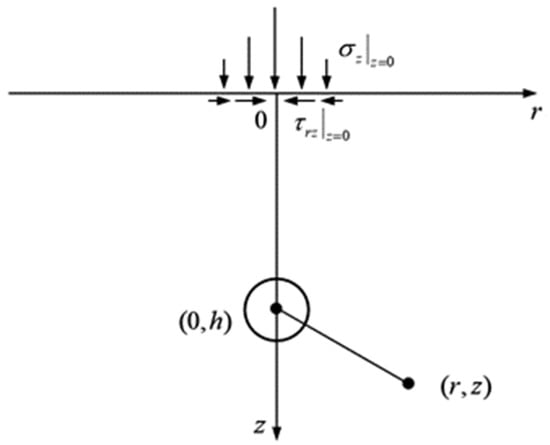
Figure 1.
Stress boundary for semi-infinite cavity expansion correction. σz is the vertical stress; r and z are the horizontal and vertical positions, respectively; τr is the shear stress.
2.2. Displacement Solutions for Surrounding Soil due to Pile Penetration
Field measurements and theoretical research [5,39,40] show that the penetration of the static-pressure pile mainly causes radial displacement of the soil around the pile. Therefore, the penetration of the new pile will cause lateral compression on the old pile and will not cause pile torsion. One of the key steps to analyze the stress and deformation of the old pile is to obtain the radial displacement of the soil around the new pile.
For static-pressure pile penetration, any micro-segment of the pile can be considered as a spherical cavity expansion of the same volume, which is shown in Figure 2. It can be expressed as:
where d0 is the diameter of the static-pressure pile; a0 is the radius of the equivalent spherical cavity, and it can be expressed as:
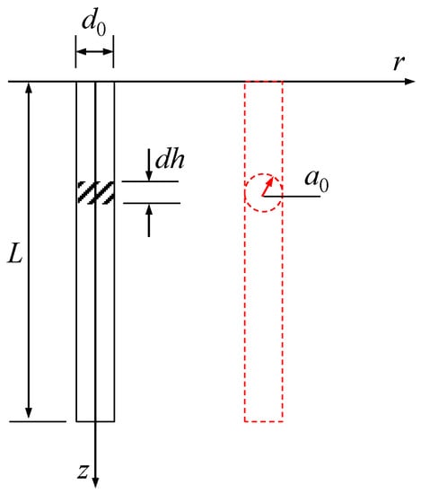
Figure 2.
Equivalent simulation of static-pressure pile penetration.
The squeezing displacement of a pile (assuming a length of L) pressed into the soil can be calculated as the integration of h from 0 to L:
where ur and uz are the lateral displacement and the vertical displacement, respectively; L is the pile length; and r and z are the coordinates of the calculated point position.
3. Mechanical Model of the Existing Pile under Adjacent Pile Driving
The penetration of the static-pressure pile mainly causes radial displacement of the soil around the pile. Therefore, the used pile is subjected to a load perpendicular to its axis. At this time, the old pile can be considered as an elastic foundation beam for analysis, for which the Winkler foundation model and Pasternak foundation model were adopted. Pile driving will generate excess pore water pressure in the surrounding soil, but this paper mainly analyzes the response of the used pile by calculating the displacement of the soil around the pile, so the pore water pressure in the surrounding soil is not analyzed.
The Winkler foundation model is widely used in the analysis of laterally loaded piles currently. However, the soil is regarded as a non-continuum, and the shear action between soils is neglected in this method, which is not correspondent with engineering practices. The Pasternak foundation model, based on a double-parameter foundation model which can consider shear action, is proposed for laterally loaded piles. This method successfully takes into account the change of the subgrade modulus with depth. These two foundation models are respectively used in the analysis of stress and deformation of used piles, and the types of used piles are considered, as shown in Figure 3.

Figure 3.
Analysis workflow of stress and deformation of used piles.
3.1. Response of Existing Pile Based on Winkler Model
Based on the Winkler foundation model, The concept model for the response of the existing pile caused by adjacent pile driving is shown in Figure 4. The penetrated depth and diameter of the new pile are respectively L and d0; the depth and diameter of the existing pile are H and D0, respectively.
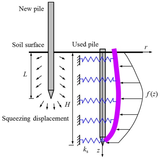
Figure 4.
Equivalent simulation of static-pressure pile penetration.
From Equation (5), the lateral displacement can be obtained. Under the existing pile, the soil displacement would be limited. In this section, the soil is assumed as homogeneous and continuous. The adjacent pile and soil have deformation compatibility. The final lateral displacement is equal to the squeezing displacement, which can be expressed as ω(z). Based on the Winkler foundation model, the lateral earth pressure can be expressed as:
where p is the lateral pressure in the unit’s existing pile, and ks is the lateral modulus in the existing pile, which can be expressed as [41]:
where Es is deformation modulus of pile-side soil; EpIp is the flexural rigidity of section in existing pile; and ν is the Poisson’s ratio.
According to the deflection curve equation, the unit length of the existing pile can be seen as an elastic foundation beam. The governing equation of displacement including the existing pile and adjacent pile can be expressed as:
For the existing pile: if the pile is a friction pile, the pile tip can be seen as a free end; if the pile is end-bearing, the pile tip can be considered as a fixed end. Because the superstructure has been removed, the top of the existing pile can be seen as a free end, and the bending moment and shear stress are assumed as zero. The direct solving of Equation (8) only applies to homogeneous soils. For layered soils, the difference method should be used.
The existing piles are divided into n equal segments along the length of the existing piles, and the length of each segment is h. Equation (8) can be given as:
Then, Equation (9) can be written as:
where:
On the basis of physical relationships, the turning angle, pile bending moment and shear stress can be written as:
The lateral displacement of the existing pile can be obtained as follows:
Based on the boundary conditions, the stiffness matrix can be derived.
- Case 1:
If the existing pile is a friction pile, the pile top and pile tip are free. The boundary can be expressed as:
- (i).
- For i = 0,
Eliminating ω−2 and ω−1, Equation (17) can be written as:
- (ii).
- For i = 1,
Eliminating ω−1, Equation (19) can be written as:
- (iii).
- For i = n − 1,
Eliminating ωn+1, Equation (21) can be written as:
- (iv).
- For i = n,
Eliminating ωn+1 and ωn+2, Equation (23) can be written as:
Substituting Equations (16)–(24), the stiffness matrix can be expressed as:
- Case 2:
If the existing pile is the end-bearing pile, the pile top is free, and the pile tip is fixed. The boundary can be expressed as:
- (i).
- For i = 0,
Eliminating ω−2 and ω−1, Equation (27) can be written as:
- (ii).
- For i = 1,
Eliminating ω−1, Equation (29) can be written as:
- (iii).
- For i = n − 1,
Eliminating ωn+1, Equation (31) can be written as:
- (iv).
- For i = n,
Eliminating ωn+1 and ωn+2, Equation (33) can be written as:
Substituting Equations (26)–(34), the stiffness matrix can be expressed as:
3.2. Response of Existing Pile Based on Pasternak Foundation Model
The Winkler foundation model fails to account for soil continuity. To this end, based on the Pasternak foundation model, a mathematical model for reflecting the response of the existing pile is proposed in this section. Another mechanical model of the existing pile under new pile penetration based on the Pasternak foundation model is proposed, as shown in Figure 5.
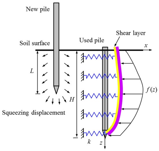
Figure 5.
Pile–soil interaction model for Pasternak foundation.
The existing pile is seen as a rectangular beam with a width of D0 and a stiffness of EpIp. If the pile and surrounding soil satisfy deformation-coordinated condition, the differential equation for the equilibrium based on the Pasternak foundation model can be given as:
where G is the shear modulus, which can be expressed as:
Considering the shear stress, the lateral earth pressure can be expressed as:
where ur″(z) is the second-order derivative of the squeezing displacement.
Equation (36) cannot be solved directly for layered soil; it needs to be solved using the difference method. Thus, Equation (36) can be written in difference form:
Similarly, Equation (39) can be rewritten as:
where:
The lateral displacement of the existing pile can be given as:
- (i).
- For a friction pile, the stiffness matrix can be written as:
- (ii).
- For an end-bearing pile, the stiffness matrix can be written as:
4. Simulation of the Response of the Used Pile under New Pile Penetration
4.1. Model Setting
In this section, a 3D numerical model of the existing pile under new pile penetration is employed, as shown in Figure 6. The soil is 30 m high with a radius of 10 m. The new pile has a diameter of 0.5 m and a length of 20 m. The new pile penetrates at the center of the soil. The existing pile has a length of 20 m and a diameter of 0.5 m. The existing pile’s center is 2 m away from the new pile’s penetration position, which is 4 times the diameter of the pile. To ensure computational stability, the model is presented with a small hole with a radius of 0.1 m at the center of the new pile’s penetration position, and an auxiliary pipe with a radius of 0.1 m is added at the bottom of the pile end, as shown in Figure 7. Thus, the equivalent radius of the new pile model can be calculated as:
where Rm and rt are the radii of the new pile and auxiliary pipe, respectively; D0 is the theoretical radius of the new pile. Therefore, Rm can be written as:
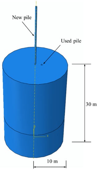
Figure 6.
FEM model of new pile penetration with existing pile in stratum.
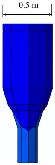
Figure 7.
Pile tip optimization.
To verify the validity of the theoretical result, the pile, pipe and soil are simulated by a linear elastic model, which can be described by Young’s modulus and Poisson’s ratio. The material parameters of the soil and pile are shown in Table 1.

Table 1.
Parameters of soil and pile.
The proposed numerical model contains two steps: ground stress equilibration and new pile penetration. To eliminate the initial soil deformation, the ground stress equilibration is achieved by the geostatic step, where the soil gravity is applied through body force.
The second step is to simulate the new pile penetration, and the displacement control method is employed, which means a vertical downward displacement is imposed on the top of the penetrated pile. In this step, the underside boundary is fixed, and the lateral displacement of the side boundary is constrained. Meanwhile, the interface soil boundary is free, and the lateral displacement of the penetrated pile is limited.
4.2. Comparison of Analytical Solution and Simulation
Figure 8 shows the lateral displacement of the existing pile at 5 m, 10 m, 15 m and 20 m of new pile penetration. It can be seen from Figure 8 that the existing pile causes lateral displacement away from the new pile as the new pile penetrates, and the deeper the penetration, the greater the lateral displacement. This is attributable to the significant squeezing impact induced by the new pile’s penetration.
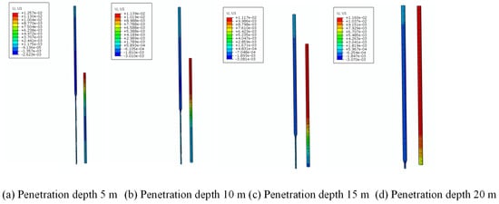
Figure 8.
Nephogram of existing pile lateral displacement caused by new pile penetrating to different depths.
Figure 9 and Figure 10 present a comparison of the analytical results of the Winkler foundation model and the simulation. Figure 9 shows the result of the pile top and pile end being free. Figure 10 displays the result of the pile top being free and the pile end being fixed. Both the theoretical results and the numerical results demonstrate that when the new pile’s penetration depth grows, the existing pile’s deformation increases as well. There is a good agreement between the two in terms of the deformation trend. Within 10 m depth of new pile penetration, the theoretical results and simulation results are basically consistent. When the static-pressure pile penetrates to a depth greater than 10 m, the theoretical results are slightly greater than the simulation results. This is mainly due to the usage of a pre-set auxiliary pipe in the simulation. Meanwhile, the Winkler model mainly reflects the squeezing effect, but the shear stress effect on the surrounding soil cannot be well reflected. This may also result in the lateral displacement of the theoretical calculation being larger than that of the simulation results.
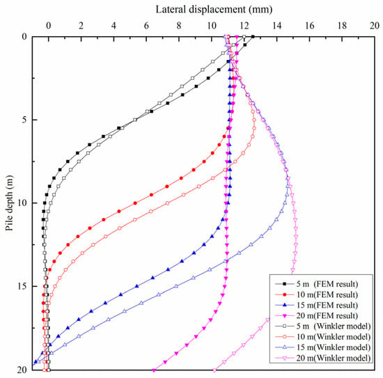
Figure 9.
Comparison of calculation results between numerical simulation and Winkler foundation model with pile tip free.
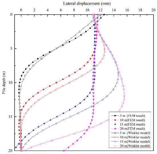
Figure 10.
Comparison of calculation results between numerical simulation and Winkler foundation model with pile tip fixed.
From Figure 9 and Figure 10, it can be found that different forms of pile end restraint have little effect on the lateral deformation at 5 m, 10 m and 15 m of new pile penetration. However, when the new pile penetration is close to 20 m, the lateral displacement of the existing pile in the theoretical results for the fixed case of the pile end is significantly smaller than for the free case of the pile end. This is because when the penetration length is short, the influence of the boundary conditions is limited to the upper pile body. Moreover, when the penetration depth is close to the length of the existing pile, the fixed boundary conditions limit the displacement of the bottom pile body, which has a significant impact on the deformation of the bottom of the pile body.
Figure 11 and Figure 12 display a comparison of analytical results of the Pasternak foundation model and the simulation results; Figure 11 and Figure 12 show the results of the pile end being free and the pile end being fixed, respectively. The analytical results are in general agreement with those of the simulation, as shown in Figure 11 and Figure 12. That means both the Winkler model and Pasternak model used in this article can better reflect the deformation pattern of the adjacent existing pile under the penetration of a static-pressure pile.
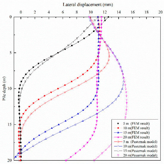
Figure 11.
Comparison of calculation results between numerical simulation and Pasternak foundation model with pile tip free.
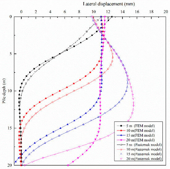
Figure 12.
Comparison of calculation results between numerical simulation and Pasternak foundation model with pile tip fixed.
From Figure 9, Figure 10, Figure 11 and Figure 12, it can be found that the difference between the results of the two analytical models is mainly in the deformation near the top of the existing pile. Figure 13 displays the comparison of lateral deformation of the existing pile body between the Winkler foundation model and the Pasternak foundation model. It is worth noting that the lateral deformation of the existing pile body computed by the Pasternak foundation model is larger than the results of the Winkler foundation model, which is compatible with the findings of Liang et al. [42].
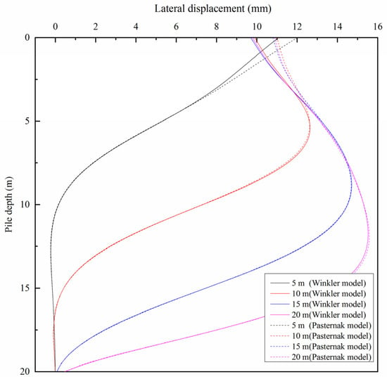
Figure 13.
Comparison of calculation results between Winkler foundation model and Pasternak foundation model.
The values of parameters such as shear layer thickness and shear modulus for the Pasternak foundation model are difficult to obtain. As a result, the Winkler foundation model is employed for computational analysis in the following discussion of the affecting factors.
5. Results and Discussion
5.1. Influence of the Spacing between the Adjacent Pile and Existing Pile
To investigate the influence of the distance between the existing and adjacent piles on the existing single-pile response, Figure 14 and Figure 15 show the deformation and bending moment of the existing pile at four different distances (i.e., 1.5 m, 2 m, 2.5 m and 3 m) adopted for calculation at 10 m and 20 m of new pile penetration.
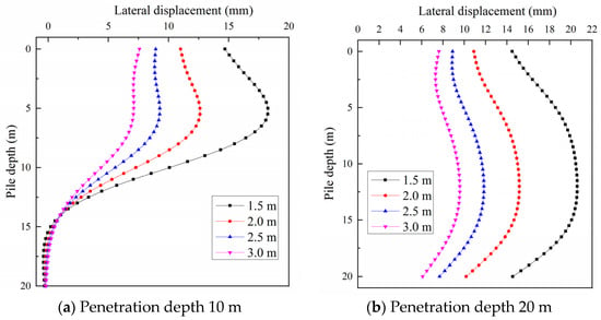
Figure 14.
Influence of the distance between the used and new piles on lateral displacement of used pile.
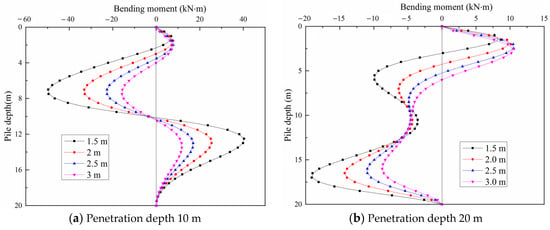
Figure 15.
Influence of the distance between the used and new piles on bending moment of used pile.
It can be seen that the lateral displacement generated by an existing pile increases significantly as the distance decreases. Furthermore, when the distance is short, the existing pile’s lateral displacement grows dramatically with increasing distance. At 10 m pile penetration, when the distance was lowered from 2 m to 1.5 m, the maximum value of lateral displacement of existing piles increased by 5.65 mm, from 12.62 mm to 18.27 mm; meanwhile, when the distance was reduced from 3 m to 2.5 m, the maximum value of lateral displacement increased by only 2.16 mm, from 7.11 to 9.27 mm. At 20 m pile penetration, the highest lateral displacement of the existing pile rose from 15.17 mm to 20.61 mm, with a 5.47 mm rise when the distance is lowered from 2 m to 1.5 m; when the distance was lowered from 3 m to 2.5 m, the highest lateral displacement rose by just 2.06 mm, from 9.78 mm to 11.84 mm (as shown in Table 2). This indicates that increasing the spacing between the existing pile and the new pile has a major impact on minimizing the squeezing effect. Too small a distance will affect the bearing capacity of existing piles.

Table 2.
Lateral displacement variation due to distance variation between the used and new piles.
5.2. Influence of the Diameter of the New Pile
Figure 16 and Figure 17 represent the effect of the new pile diameter on the existing pile response, including the lateral displacement and bending moment. For this end, three different values of diameter (i.e., 0.4 m, 0.5 m and 0.6 m) are computed as examples.
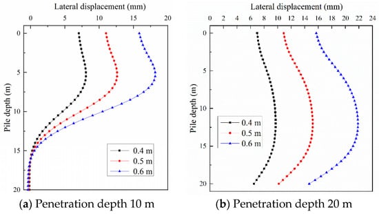
Figure 16.
Influence of the diameter of the new pile on the lateral displacement of the used pile.
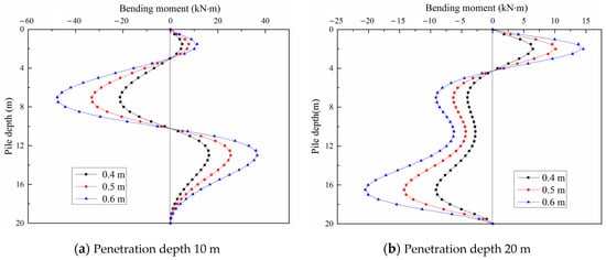
Figure 17.
Influence of the diameter of the new pile on the bending moment of the used pile.
According to Figure 16, when the diameter of the pile increases, the lateral displacement of the present pile increases dramatically. At 10 m of pile penetration, when the pile diameter was enlarged from 0.4 m to 0.5 m, the maximum lateral displacement of the existing pile increased by 4.54 mm, from 8.08 mm to 12.62 mm; when the pile diameter was extended from 0.5 m to 0.6 m, the maximum value of lateral displacement rose by 5.55 mm, from 12.62 mm to 18.17 mm. At 20 m of pile penetration, when the pile diameter was expanded from 0.4 m to 0.5 m, the maximum lateral displacement of the existing pile rose by 5.46 mm, from 9.71 mm to 15.17 mm; when the pile diameter was extended from 0.5 m to 0.6 m, the maximum value of lateral displacement rose by 6.68 mm, from 15.17 mm to 21.85 mm. The Table 3 exhibits the lateral displacement variation due to diameter variation of new pile. The results suggest that lowering the pile diameter is more significantly effective than increasing the piles’ spacing in minimizing the squeezing effect, and slender piles are recommended for new piles, as shown in Table 3.

Table 3.
Lateral displacement variation due to diameter variation of new piles.
Figure 17a,b show the bending moment of the existing pile at 10 m and 20 m of new pile penetration, respectively. The two figures show that the bending moment of the existing pile also increases as the diameter of the new pile increases. It is worth noting that the change in the diameter of the new pile has no effect on the distribution and neutral point of the bending moment of the existing pile.
5.3. Usage of Pre-Drilling Technology in the New Pile Penetration
Pre-drilling technology is a typical approach for reducing the squeezing impact of a static-pressure pile in geotechnical engineering. Accordingly, the pre-drilling method can also be used to decrease the effect of new pile penetration on an adjacent pile. To analyze the effect of pre-drilling and drilling depth, Equation (5) should be improved in this section. Assuming that the penetration depth of the new pile is L, the pre-drilling depth is L′ and the diameter of the pre-drilling hole is dr, the equivalent pile diameter of the new pile within the pre-drilling depth can be written as:
Considering pre-drilling, the lateral displacement of the existing pile under new pile penetration can be described as follows:
The squeezing displacement calculated by Equation (48) can be used to analyze the adjacent pile response under new pile penetration. In this section, the length and diameter of the existing pile are 10 m and 0.5 m, respectively. The depth of new pile penetration is 10 m, with a diameter of 0.5 m. Other parameters are the same as in the previous section. The lateral displacement and bending moment of the existing pile are calculated, including the condition without pre-drilling and those with pre-drilling depths of 2.5 m, 5 m and 7.5 m.
According to Figure 18, pre-drilling can significantly reduce the lateral displacement of the existing pile caused by the squeezing impact from the new pile penetration. Meanwhile, with the increasing length of pre-drilling, the effect on the lateral displacement of the upper pile body becomes smaller. It is worth noting that the pre-drilling technology greatly reduces the lateral displacement of the lower pile, which indicates that pre-drilling causes a significant reduction in the squeezing effect.
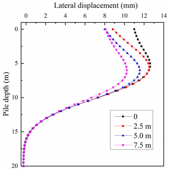
Figure 18.
Influence of the pre-drilling depths of the new pile on the lateral displacement of the used pile.
Figure 19 shows the bending moment of the existing pile with the condition of pre-drilling. It can be found that the bending moment is less affected by pre-drilling than is the lateral displacement. Generally speaking, the greater the depth of pre-drilling, the smaller the pile bending moment.
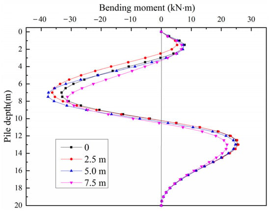
Figure 19.
Influence of the pre-drilling depths of the new pile on the bending moment of the used pile.
6. Conclusions
The main objective of this work was to offer an analytical solution for the response of an existing pile under new pile penetration. First, displacement solutions for the soil under new pile penetration are calculated by the theory of cavity expansion. Then, according to the Winkler model and the Pasternak model, the bending moment and deformation of the existing pile were calculated, respectively. Meanwhile, a 3D numerical model for the response of an adjacent pile under new pile penetration was developed. The validity and accuracy of the analytical models were examined by comparison with the proposed numerical model. Subsequently, several critical factors and pre-drilling technology were discussed for minimizing the impact of new pile penetration. The following are some of the major conclusions reached:
- The results of this paper’s theoretical analysis and numerical simulation are basically consistent, which indicates that the accuracy of the theoretical solution of this paper is verified.
- The form of the pile end only affects the deformation near the pile end. The influence of the form of the pile end is small and can be considered as the pile end being free when the depth of the new pile is less than the length of the existing pile. When the new pile penetration is close to or beyond the existing pile end, the form of pile end has a greater impact and needs to be considered carefully.
- The distance of new piles from existing piles and the diameter of new piles have a greater influence on the deformation of existing piles. With an increase in pile diameter, the existing pile deformation gradually increases. As the distance between an existing pile and a new pile increases, the existing pile deformation decreases significantly.
Author Contributions
Conceptualization, J.C. and P.O.; methodology, J.C. and J.Z.; software, J.Z.; formal analysis, Z.Y.; investigation, J.C.; resources, J.C. and J.Z.; data curation, Z.Y.; writing—original draft preparation, J.C. and P.O.; writing—review and editing, J.Z. and Z.Y. All authors have read and agreed to the published version of the manuscript.
Funding
This research was funded by the National Natural Science Foundation of China (Grant 52108328).
Institutional Review Board Statement
Not applicable.
Informed Consent Statement
Not applicable.
Data Availability Statement
The data are contained within the article.
Conflicts of Interest
The authors declare no conflict of interest.
References
- Longarini, N.; Crespi, P.; Zucca, M.; Scamardo, M. Numerical approches for soil-structure interaction in a historical industrial masonry building rehabend. In Proceedings of the 2022 9th Euro-American Congress on Construction Pathology, Rehabilitation Technology and Heritage Management, Granada, Spain, 13–16 September 2022; pp. 770–778. [Google Scholar]
- Cui, J.F.; Li, J.P.; Xiao, J.Z.; Yao, J.P.; Yang, Z.K. Reclamation pathway of waste piles: A case study in Shanghai. J. Clean. Prod. 2020, 253, 119919. [Google Scholar] [CrossRef]
- Shao, W.; Sun, Q.; Xu, X.; Yue, W.; Shi, D. Durability life prediction and horizontal bearing characteristics of CFRP composite piles in marine environments. Constr. Build. Mater. 2023, 367, 130116. [Google Scholar] [CrossRef]
- Sagaseta, C. Analysis of undrained soil deformation due to ground loss. Géotechnique 1987, 37, 67–86. [Google Scholar] [CrossRef]
- Sagaseta, C.; Whittle, A.J. Prediction of ground movements due to pile driving in clay. J. Geotech. Geoenviron. Eng. 2001, 127, 55–66. [Google Scholar] [CrossRef]
- Yu, H.S.; Houlsby, G.T. Finite cavity expansion in dilatants soils: Loading analysis. Géotechnique 1991, 41, 173–183. [Google Scholar] [CrossRef]
- Silvestri, V.; Abou-Samra, G. Application of the exact constitutive relationship of modified Cam clay to the undrained expansion of a spherical cavity. Int. J. Numer. Anal. Methods Geomech. 2011, 35, 53–66. [Google Scholar] [CrossRef]
- Chen, S.L.; Abousleiman, Y.N. Exact undrained elasto-plastic solution for cylindrical cavity expansion in modified Cam Clay soil. Géotechnique 2012, 62, 447–456. [Google Scholar] [CrossRef]
- Chen, S.L.; Abousleiman, Y.N. Exact drained solution for cylindrical cavity expansion in modified Cam Clay soil. Géotechnique 2013, 63, 510–517. [Google Scholar] [CrossRef]
- Chen, S.L.; Abousleiman, Y.N. Drained and undrained analyses of cylindrical cavity contractions by Bounding Surface plasticity. Can. Geotech. J. 2016, 53, 1398–1411. [Google Scholar] [CrossRef]
- Wang, H.; Li, L.; Li, J.P.; Sun, D.A. Drained expansion responses of a cylindrical cavity under biaxial in-situ stresses: Numerical investigation with implementation of anisotropic S-CLAY1 model. Can. Geotech. J. 2022, 60, 198–212. [Google Scholar] [CrossRef]
- Chen, H.H.; Mo, P.Q. An undrained expansion solution of cylindrical cavity in SANICLAY for K0-consolidated clays. J. Rock Mech. Geotech. Eng. 2022, 14, 922–935. [Google Scholar] [CrossRef]
- Mcmahon, B.T.; Haigh, S.K.; Bolton, M.D. Cavity expansion model for the bearing capacity and settlement of circular shallow foundations on clay. Géotechnique 2013, 63, 746–752. [Google Scholar] [CrossRef]
- Vrakas, A. A rigorous semi-analytical solution for undrained cylindrical cavity expansion in critical state soils. Int. J. Numer. Anal. Methods Geomech. 2016, 40, 2137–2160. [Google Scholar] [CrossRef]
- Vrakas, A. Relationship between small and large strain solutions for general cavity expansion problems in elasto-plastic soils. Comput. Geotech. 2016, 76, 147–153. [Google Scholar] [CrossRef]
- Yang, J.; Tham, L.; Lee, P.; Yu, F. Observed performance of long steel H-piles jacked into sandy soils. J. Geotech. Geoenviron. Eng. 2006, 132, 24–35. [Google Scholar] [CrossRef]
- Stringer, M.; Madabhushi, G. The effect of pile installation method on dynamic pile response. Int. J. Phys. Model. Geotech. 2011, 11, 87–99. [Google Scholar] [CrossRef]
- Jardine, R.J.; Zhu, B.T.; Foray, P.; Yang, Z.X. Measurement of stresses around closed-ended displacement piles in sand. Géotechnique 2013, 63, 1–17. [Google Scholar] [CrossRef]
- D’Arezzo, F.B.; Haigh, S.; Talesnick, M.; Ishihara, Y. Measuring horizontal stresses during jacked pile installation. Geotech. Eng. 2006, 168, 306–318. [Google Scholar]
- Zarrabi, M.; Eslami, A. Behavior of piles under different installation effects by physical modeling. Int. J. Geomech. 2016, 16, 04016014. [Google Scholar] [CrossRef]
- Basu, P.; Prezzi, M.; Salgado, R.; Chakraborty, T. Shaft resistance and setup factors for piles jacked in clay. J. Geotech. Geoenviron. Eng. 2014, 140, 0001018. [Google Scholar] [CrossRef]
- Engin, H.K.; Brinkgreve, R.B.J.; Tol, A.F.V. Simplified numerical modelling of pile penetration—The press-replace technique. Int. J. Numer. Anal. Methods Geomech. 2015, 39, 1713–1734. [Google Scholar] [CrossRef]
- Engin, H.K.; Brinkgreve, B.J.; Tol, A.F.V. Approximation of pile installation effects: A practical tool. Geotech. Eng. 2015, 168, 319–334. [Google Scholar] [CrossRef]
- Phuong, N.T.V.; Van Tol, A.F.; Elkadi, A.S.K.; Rohe, A. Numerical investigation of pile installation effects in sand using material point method. Comput. Geotech. 2016, 73, 58–71. [Google Scholar] [CrossRef]
- Tehrani, F.S.; Nguyen, P.; Brinkgreve, R.B.J.; Van Tol, A.F. Comparison of press-replace method and material point method for analysis of jacked piles. Comput. Geotech. 2016, 78, 38–53. [Google Scholar] [CrossRef]
- Nontananandh, S.; Kuwahara, S.; Shishido, K.; Inazumi, S. Influence of perforated soils on installation of new piles. Appl. Sci. 2022, 12, 7712. [Google Scholar] [CrossRef]
- Jayasinghe, L.B.; Waldmann, D.; Shang, J. Impact of Pile Punching on Adjacent Piles: Insights from a 3D Coupled SPH-FEM Analysis. Appl. Mech. 2020, 1, 47–58. [Google Scholar] [CrossRef]
- Poulos, H.G.; Chen, L.T.; Hull, T.S. Model tests on single piles subjected to lateral soil movement. Soil Found. 1995, 35, 85–92. [Google Scholar] [CrossRef]
- Chen, L.T.; Poulos, H.G.; Hull, T.S. Model tests on pile groups subjected to lateral soil movement. Soil Found. 1997, 37, 1–12. [Google Scholar] [CrossRef]
- Leung, C.F.; Chow, Y.K.; Shen, R.F. Behavior of pile subject to excavation induced soil movement. J. Geotech. Geoenviron. Eng. 2000, 126, 947–954. [Google Scholar] [CrossRef]
- Leung, C.F.; Lim, J.K.; Shen, R.F.; Chow, Y.K. Behavior of pile groups subject to excavation-induced soil movement. J. Geotech. Geoenviron. Eng. 2003, 129, 58–65. [Google Scholar] [CrossRef]
- Leung, C.F.; Ong, D.E.L.; Chow, Y.K. Pile Behavior due to excavation-induced soil movement in clay II: Collapsed wall. J. Geotech. Geoenviron. Eng. 2006, 132, 45–53. [Google Scholar] [CrossRef]
- Lee, G.T.K.; Ng, C.W.W. Effects of Advancing Open Face Tunneling on an Existing Loaded Pile. J. Geotech. Geoenviron. Eng. 2005, 131, 193–201. [Google Scholar] [CrossRef]
- Cui, J.; Yang, Z.; Azzam, R. Field Measurement and Numerical Study on the Effects of Under-Excavation and Over-Excavation on Ultra-Deep Foundation Pit in Coastal Area. J. Mar. Sci. Eng. 2023, 11, 219. [Google Scholar] [CrossRef]
- Poulos, H.G.; Chen, L.T. Pile response due to excavation-induced lateral soil movement. J. Geotech. Geoenviron. Eng. 1997, 123, 94–99. [Google Scholar] [CrossRef]
- Poulos, H.G.; Chen, L.T. Pile response due to unsupported excavation-induced lateral soil movement. Can. Geotech. J. 1996, 33, 670–677. [Google Scholar] [CrossRef]
- Chen, L.T.; Poulos, H.G. Piles subjected to lateral soil movements. J. Geotech. Geoenviron. Eng. 1997, 123, 802–811. [Google Scholar] [CrossRef]
- Zhu, N.; Shi, J.Y.; Chen, H.F. A method for cavity expansion in semi-infinite soil. Rock Soil Mech. 2006, 27, 257–260+267. (In Chinese) [Google Scholar]
- Hagerty, D.J.; Peck, R.B. Heave and lateral movements due to pile driving. J. Soil Mech. Found. Div. ASCE 1971, 97, 1513–1532. [Google Scholar] [CrossRef]
- Huang, J.H.; Liang, N.; Chen, C.H. Ground response during pile driving. J. Geotech. Geoeniron. Eng. 2001, 127, 939–949. [Google Scholar]
- Vesic, A.S. Bending of Beams Resting on Isotropic Elastic Solids. J. Soil Mech. Found. Eng. 1961, 87, 35–53. [Google Scholar]
- Liang, F.Y.; Li, Y.C.; Huang, M.S. Simplified method for laterally loaded piles based on Pasternak double-parameter spring model for foundations. Chin. J. Geotech. Eng. 2013, 35, 300–304. [Google Scholar]
Disclaimer/Publisher’s Note: The statements, opinions and data contained in all publications are solely those of the individual author(s) and contributor(s) and not of MDPI and/or the editor(s). MDPI and/or the editor(s) disclaim responsibility for any injury to people or property resulting from any ideas, methods, instructions or products referred to in the content. |
© 2023 by the authors. Licensee MDPI, Basel, Switzerland. This article is an open access article distributed under the terms and conditions of the Creative Commons Attribution (CC BY) license (https://creativecommons.org/licenses/by/4.0/).