Abstract
In order to accurately locate personnel in underground spaces, positioning equipment is required to be mounted on wearable equipment. But the wearable inertial personnel positioning equipment moves with personnel and the phenomenon of measurement reference wobble (referred to as moving base) is bound to occur, which leads to inertial measurement errors and makes the positioning accuracy degraded. A neural network-assisted binocular visual-inertial personnel positioning method is proposed to address this problem. Using visual-inertial Simultaneous Localization and Mapping to generate ground truth information (including position, velocity, acceleration data, and gyroscope data), a trained neural network is used to regress 6-dimensional inertial measurement data from the IMU data fragment under the moving base, and a position loss function is constructed based on the regressed inertial data to reduce the inertial measurement error. Finally, using vision as the observation quantity, the point feature and inertial measurement data are tightly coupled to optimize the mechanism to improve the personnel positioning accuracy. Through the actual scene experiment, it is verified that the proposed method can improve the positioning accuracy of personnel. The positioning error of the proposed algorithm is 0.50%D, and it is reduced by 92.20% under the moving base.
1. Introduction
With the continuous development of modern society, the development process of underground space is accelerating, and people spend more than 90% of their time living and working indoors or underground. Globally, there are more than 1 million emergencies such as earthquakes, fires, and mining accidents every year, which can cause huge casualties and material losses when the events occur and during the rescue process. Therefore, the demand for public safety, emergency rescue, and other fields is driving the explosive growth of high-precision and high-efficiency navigation and location services in underground space.
The commonly used underground space localization techniques include UWB (Ultra Wide Band) localization based on wireless signals, WLAN (Wireless Local Area Networks), and infrared, as well as sensor-based IMU localization and visual localization. Wireless signal-based localization methods are highly susceptible to occlusion and interference in underground space and have poor stability. Methods using inertial sensor localization, such as the PDR algorithm [1,2,3], ZUPT algorithm [4], etc., have the advantages of small size, full autonomy, all-weather use, and are not easily affected by external environmental interference and high update frequency. However, the single inertial sensor will drift due to quadratic integration and changes in human physique and walking posture. The visual positioning method has the advantages of relatively low cost, high positioning accuracy, and no cumulative error under long-time measurement [5]. However, the camera will have motion blur and feature-matching failure when it moves too fast or is obscured.
It is difficult to achieve high-accuracy positioning in underground space using a single positioning method [6]. A combined positioning approach that incorporates multiple sensors can make full use of the complementary advantages between sensors to improve the accuracy and robustness of positioning [7]. The observation information using vision can effectively estimate and correct the accumulated errors in IMU readings, while for fast movements in a short period, inertial sensors can provide some better estimates and maintain a better estimate of the position even during the period when the vision is obscured, resulting in invalid data; therefore, the positioning approach using a combination of vision and IMU has advantages.
Depending on the back-end optimization, research on visual-inertial localization [8,9] can be divided into filter-based and optimization-based approaches. The following categories of filter-based methods are available: extended Kalman filter (EKF)-based algorithms such as MonoSLAM [10]; particle filter-based methods such as FastSLAM [11] and its monocular SLAM alternative; multi-state constrained Kalman filter (MSCKF) [12,13]; and stereo multi-state constrained Kalman filter(S-MSCKF) [14].
The filter-based approach estimates both the pose of the camera and the position of the landmark in a state vector, which is a potential source of scalability inefficiency and the Markovian nature of the filter-based approach, i.e., the inability to establish the relationship between a moment and all previous states, so the mainstream visual-inertial tight coupling research is currently based on a nonlinear optimization approach.
SVO [15] is a semi-direct visual odometry, which combines the feature point method and the direct method, and finally calculates the bit pose based on optimization. The Flying Robotics Laboratory of the Hong Kong University of Science and Technology [16] proposed VINS-mono (visual-inertial system), a tightly coupled monocular visual-inertial SLAM system with a better system framework, including five parts: observation preprocessing, initialization, joint local visual-inertial optimization, global map optimization, and closed-loop detection. Campos et al. proposed the ORB-SLAM3 [17] system, which is one of the most accurate and robust algorithms available. ORB-SLAM3 is the first open-source algorithm that can support pure vision, visual-inertial, and multi-map reuse.
Visual odometry localization regarding pedestrians has received increasing attention in recent years. Alliez et al. [18] proposed a wearable real-time multi-sensor system for human localization and 3D mapping. The system incorporates IMU, laser SLAM, and visual SLAM sensors and was tested in a long-trajectory (185 m) underground space with a drift of 0.75 cm (0.41%). Kachurk et al. [19] proposed a wearable cooperative localization system for real-time indoor localization. The application scenario is mainly when GPS fails, such as in smoky rooms, stairs, and indoor environments with extreme lighting. The maximum error was 1.1% and the average error was 0.55% in a distance test of 950 m. Ruotsalainen et al. [20] investigated an infrastructure-free simultaneous localization with mapping and context recognition for tactical situational awareness. Based on the derived measurement errors, a particle filtering approach is proposed to combine with a monocular camera and foot-mounted inertial measurement unit. The error was 2.54 m in a 340 m closed-loop test of going up and down stairs and walking, which is a much higher accuracy compared to the 6.53 m error of pure PDR. Wang et al. [21] proposed a new method to exploit the short-term reliability of pedestrian trajectory derivation (PDR) to aid visual personnel localization and reduce localization errors. The method proposes that the PDR-assisted visual monitoring system can automatically select the best effect switching between VIO and PDR to provide a more accurate position indoors based on the short-term reliability of PDR. Chai et al. [22] presented a novel pedestrian dead reckoning (PDR)-aided visual-inertial SLAM, taking advantage of the enhanced vanishing point (VP) observation. The VP is integrated into the visual-inertial SLAM as an external observation without drift error to correct the system drift error. In addition, pedestrian dead reckoning velocity was employed to constrain the double integration result of acceleration measurement from the IMU. The accumulated drift error of the proposed system was less than 1 m. For inherent cumulative global drift and potential divergence facing texture-less indoor regions, Dong et al. [23] proposed a visual-inertial odometry assisted by pedestrian gait information for smartphone-based indoor positioning. The method mainly builds two additional state constraints, pedestrian velocity and step displacement, obtained by the pedestrian dead reckoning (PDR) algorithm for the visual-inertial tracking system. For each step, the corresponding residual term of step length and velocity constraints is constructed and added to the cost function for nonlinear sliding-window optimization. Niu et al. [24] proposed a pedestrian POS solution for infrastructure-free environments based on the fusion of foot-mounted IMU and a stereo camera. The stereo camera detects loop closure for mitigating the accumulated error; the foot-mounted pedestrian dead reckoning (Foot-PDR) provides reliable continuous trajectories using the IMU when the visual-based system degrades or crashes. In the office building and parking lot tests, the position error was 0.237 m and 0.227 m. The positioning accuracy of all articles is shown in Table 1.

Table 1.
Pedestrian positioning method and accuracy. X means not mentioned.
The advent of deep learning offers new possibilities for extracting information from IMU data. Chen et al. [25] first proposed an LSTM structure that outputs relative displacements in two-dimensional polar coordinates and splices them to get the position. Hang Yan et al. proposed Robust IMU Double Integration (RIDI) [26] and Robust Neural Inertial Navigation in the Wild: Benchmark, Evaluations, & New Methods(RoNIN) [27]. The two methods assumed that the orientation can be achieved from the Android device, thus rotating the IMU data to gravity-aligned frames. The former optimized the bias by regressing the velocity but still used the corrected IMU data to compute a quadratic integration to obtain the position, while the latter integrated the regressed velocity directly. Liu et al. [28] used the EKF to fuse the raw IMU data with the relative displacement measurements from the Residual Network.
For underground space personnel positioning, the wearable visual-inertial positioning undershirt equipment used in this paper is shown in Figure 1, whose inertial measurement reference will produce a moving base phenomenon with human motion, which will produce positioning error if solved according to the traditional Strapdown inertial navigation algorithm. Therefore, this paper proposes a neural network-assisted visual-inertial personnel positioning method to solve the inertial measurement errors caused by the moving base and improve positioning accuracy. The novelty of this work lies in proposing an LSTM network to regress six-dimensional IMU data and constructing two location loss functions. The regressed six-dimensional IMU data are then fused with visual to improve person localization. The contributions of this paper are as follows.

Figure 1.
Wearable visual-inertial positioning undershirt equipment.
Regression of 6-dimensional inertial measurement data from the IMU data fragment under the moving base using LSTM neural network. The problem of inertial measurement error caused by the moving base is eliminated. Then, the point features are closely coupled with the inertial measurement data using vision as the observation quantity to optimize the mechanism and improve the personnel positioning accuracy.
A relative position loss function and an absolute position loss function are designed. The nature of inertial data itself is used to constrain: position information can be obtained after two integrations. Thus, the loss of neural network learning is reduced.
The remainder of this paper is organized as follows. Section 2 discusses in detail the general framework of the system, the basic mathematical description of visual-inertial, the inertial measurement error model under the dynamic base, and the neural network-assisted visual-inertial fusion localization method. Section 3 contains experiments on inertial measurement error under a dynamic base and experiments on personnel localization in an indoor–outdoor environment simulating an underground space, followed by the conclusions in Section 4.
2. Materials and Methods
In this paper, a neural network-assisted visual-inertial person localization method is proposed. The overall framework of the system is shown in Figure 2, which contains 3 parts: data preprocessing, initialization, and sliding window nonlinear optimization mechanism to estimate the positional posture. Based on RoNIN, a harness is used to attach the camera device to the body and an IMU is placed on the wearable undershirt to collect 6-dimensional inertial data. Running visual-inertial SLAM with the camera device on the body generates ground truth information (containing position information, velocity information, acceleration data, and gyroscope data). In this paper, the generated ground truth information is used as the label, the IMU data on the wearable undershirt as the training set, and the trained LSTM neural network is used to regress the 6-dimensional IMU data . Each network window is one window with N frames of IMU data, and each frame of IMU data is 6-dimensional. The input dimension of the network is , which consists of N samples of IMU data in gravity-aligned frames. Each window of the network output is N 6-dimensional IMU data, and two-position loss functions are proposed to improve the training accuracy. Finally, using vision as the observation quantity, point features and trained IMU data are combined in the sliding window to perform nonlinear optimization to solve the inertial measurement error caused by the moving base, thus improving the localization accuracy.
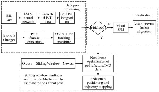
Figure 2.
Neural network-assisted visual-inertial person localization framework diagram. The framework diagram is divided into three parts: data pre-processing, initialization, sliding window nonlinear optimization Mechanism to estimate the positional pose.
2.1. Basic Description of Visual-Inertial
Section 2.1.1 introduces and derives the point feature representation and the reprojection error of the normalized plane representation of the camera. Section 2.1.2 introduces the pre-integration and the derivation of the residual term of the pre-integration in this paper.
2.1.1. Point Feature Representation
According to the pinhole camera model [29], a point in the camera world coordinate system can be mapped to a point in the pixel plane. From Equation (1), the external reference matrix (containing rotation matrix , translation vector ) converts to under the camera coordinate system; From Equation (2), the internal reference matrix (containing parameter ) converts to . Using the chi-square coordinates is introduced.
As shown in Figure 3, the th spatial point is measured in the two camera pixel planes , , respectively, and the points in the pixel planes are transformed to the camera normalization planes , by the () function, see Equations (3) and (4).

Figure 3.
Point feature reprojection residuals diagram.
Converting to , see Equation (5). In this paper, the reprojection residuals are expressed in the camera-normalized plane as shown in Equation (6):
where is the reprojection coordinate of the point feature under the frame , is the projection of the feature point in the unit camera plane of the frame . , is the position and pose of frames , is the external reference between IMU and camera. is the inverse depth of the feature point.
2.1.2. IMU Pre-Integration and Residual Measurement Model
In the continuous-time integration form, the position , velocity , and attitude of the IMU at moment are known, and the position , velocity , and attitude at moment can be recursively derived by measuring the acceleration and angular velocity of the IMU, as shown in Equation (7), where .
Typically, the frame rate of the IMU is higher than the frame rate of the cameras. The pre-integration expresses the relative observations of the IMU during the time between the two camera keyframes and can be used as a constraint on the keyframes for tightly coupled optimization. The pre-integration can decouple the IMU computation from the world coordinate system, avoiding the problem of changing Equation (7) for repeated integration of the IMU state quantities during the optimization process and reducing the computational effort. The integral model can be converted to a pre-integrated model by the transformation of Equation (8) as follows:
Substituting Equation (8) into Equation (7), the integral term in Equation (7) becomes the attitude concerning the moment of K instead of the attitude with respect to the world coordinate system:
The pre-integrated quantity is related only to the IMU measurement, which is obtained by integrating the IMU data directly over a period of time:
Further sorting of Equation (9) leads to the IMU pre-integrations , , and without considering the zero bias, and the first-order Taylor expansion approximations for the accelerometer zero bias and gyro zero bias , and expressed as , , and . Finally, the residual term of the pre-integration in this paper is shown in Equation (11):
2.2. Inertial Measurement Error Model under the Dynamic Base
To address the problem of inertial measurement errors due to wearable undershirt shaking, LSTM neural networks [30] are used to regress 6-dimensional IMU data and reduce inertial measurement errors from moving bases. In this paper, running visual-inertial SLAM relying on the camera device on the body can generate ground truth information. The generated ground truth information is used as the label and the IMU data on the wearable undershirt is used as the training set to regress the 6-dimensional IMU data () using the trained LSTM neural network. To reduce noise and improve the training accuracy, the ground truth information output from the visual-inertial SLAM is used as supervision, the IMU data in training is position-solved as a position loss function, and the longer time position is used as a loss function to ensure the accuracy for a long time. The wearable undershirt for data collection is shown in Figure 4.
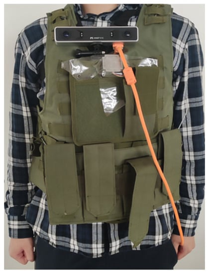
Figure 4.
Data Acquisition. The IMU data collected on the wearable are the training set, and the data collected by the camera device are the ground truth information.
2.2.1. Coordinate System Normalization
The different positions of the device placed on the wearable undershirt and the orientation of the device itself can have important effects on training. IMU sensor measurements are taken from the mobile device coordinate system (b-system), while ground truth motion trajectories are taken from the global coordinate system (n-system). In this paper, the coordinate system is defined in terms of the chest camera device orientation, using a coordinate system in which the Z-axis is aligned with gravity. In other words, any such coordinate system can be chosen as long as it remains consistent throughout the sequence. Coordinate conversion to a coordinate system with Z-axis aligned with gravity does not result in singularities or discontinuities, such as quaternions, as long as there is an appropriate rotational representation. The rotation of the IMU device direction is in the same direction as the Z-axis () rotation:
During testing, the coordinate system was defined using the orientation of the camera equipment fixed on the chest with its Z-axis aligned with gravity.
2.2.2. LSTM Network Architecture
In this paper, a special type of RNN, LSTM network (Long Short Term), is used. the memory of RNN is short term and there is a problem of gradient disappearance in RNN during backpropagation. The gradient is the value used to update the weights of the neural network, and if the gradient value becomes very small, it will not continue learning. Therefore, network layers with small gradient updates in the RNN stop learning, and these are usually the earlier layers. Since these layers do not learn, the RNN cannot remember what it has learned in longer sequences, so its memory is short-term. The LSTM is a proposed solution to overcome the short-term memory problem by introducing internal mechanisms called “gates” that regulate the flow of information. These gate structures can learn which data in a sequence are important to keep and which to delete. By doing so, they can pass relevant information along a long chain of sequences to perform predictions. The collected dataset is a long sequence, so the LSTM neural network was chosen to be used.
Figure 5 shows the architecture of the LSTM network:
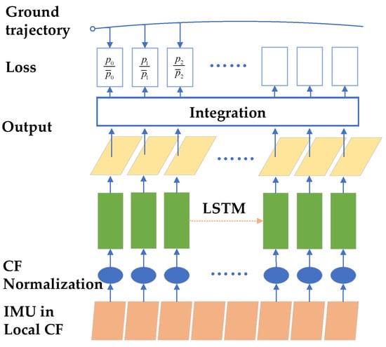
Figure 5.
LSTM architecture diagram.
From bottom to top, the first layer is the coordinate system of IMU on the device, i.e., (b-system); the second layer is the normalized coordinate system, i.e., transformed to (n-system); the third layer is the LSTM neural network; the fourth layer is the 6-dimensional IMU data output by the neural network, and the output position is solved by the fifth layer, which is supervised by the ground truth information in the uppermost layer and constitutes the loss function.
2.2.3. Loss Function
The general loss function takes the mean squared difference as the loss function; however, this effect is not good. In this paper, based on the inherent characteristics of IMU data, the location loss function is proposed as follows in Figure 6:
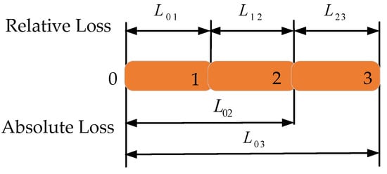
Figure 6.
Schematic diagram of the position loss function.
Two different loss functions were used in the training process: the mean square error (MSE) and the location loss function. The MSE loss on the training dataset is defined as:
Here is the 6-dimensional IMU data provided by the visual-inertial SLAM, is the output 6-dimensional IMU data after LSTM training, and is the number of data in the training set.
Position loss function:
where is the ground truth position provided by the visual-inertial SLAM and is the position solved by . is the batch size during training, is the start window of the sequence, and is the number of windows of the LSTM in the training set.
To learn long sequences of human motion relationships and reduce the cumulative error over time, an absolute position loss function is used:
where is the ground truth position provided by the visual-inertial SLAM from moment to moment , and is the position solved from moment to moment based on inertial data.
2.2.4. Data Collection and Implementation
Data collection: IMU is fixed on the wearable undershirt. A total of 2 h of a pedestrian dataset consisting of walking and walking upstairs and downstairs with 3 test persons. In this paper, we use visual-inertial SLAM to provide position estimation and 6-dimensional IMU data for the entire dataset and use these results as supervised data in the training set and ground truth trajectories in the test set. We use 70% of the dataset as training, 15% as validation, and 15% test as a subset.
Data implementation: For network training, this paper uses overlapping sliding windows on each sequence to collect input samples. Each window contains N IMU data with a total size of N × 6. In the final system, we refer to the RoNIN settings. N = 50 is chosen as a window and the Pytorch model proposed by Adam Paszke [31] is used to implement the protocol. The fully connected layer is trained by Adam optimizer with an initial learning rate of 0.0001, zero weight decay, and Dropout probability set to 0.5. A total of about 150 epochs are required for full convergence on the RoNIN dataset. On the NVIDIA 1080Ti GPU, approximately 6 h of training time is required.
2.3. Neural Network-Assisted Visual-Inertial Person Localization Method under a Moving Base
In order to further improve the accuracy of personnel positioning under the dynamic base, we pre-integrate the processed IMU data in a visual-inertial fusion navigation framework to obtain the state quantities of the current moment: position, velocity, and rotation. Finally, the pre-integrated quantities between two camera keyframes are nonlinearly optimized within a sliding window together with the visual constraints.
2.3.1. Data Pre-Processing and Initialization
We pre-processed the collected IMU data to reject incorrect data values and fill in gaps. After LSTM network processing, the IMU data are pre-integrated to obtain the state quantities of the current moment: position, velocity, and rotation.
The initialization part includes purely visual SFM (structure from motion) and visual-inertial fusion alignment, which aims to provide good initial values for visual-inertial tight-coupling optimization within the sliding window below. The purely visual SFM is tracked by point feature extraction between consecutive frames, solving the relative transformation between frames by a pair of polar geometric models and selecting the two keyframes within the sliding window with the same observation but farthest away for triangulation to obtain the inverse depth of 3D points.
Since the IMU comes with zero bias and zero bias is included as a state variable to be estimated in the sliding window optimization mechanism below, the visual inertial joint initialization can be used to estimate the initial value of the gyroscope zero bias using the rotation constraint of the visual SFM. Accelerometer zero bias has little effect due to comparison with gravity action that is neglected here. The gravity direction, velocity, and scale information of the camera can be estimated using the translational constraint.
2.3.2. Sliding Window Nonlinear Optimization Mechanism for Estimating Poses
For the correlation of visual-inertial data, all visual-inertial state quantities in the sliding window can be optimized using a tightly coupled approach based on a graph optimization framework, and Figure 7 using a factor graph approach shows the constrained relationship between the camera, the waypoint, and the IMU.
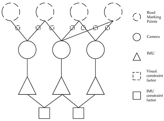
Figure 7.
Factor diagram for visual-inertial positioning system.
The state quantities to be estimated in the sliding window are shown in Equation (17), where in Equation (18) is the position, attitude, velocity, acceleration zero bias, and gyroscope zero bias state quantities of the th data; and is the inverse depth of all point features seen by the camera in the sliding window.
Based on the constructed visual constraint information between the two keyframes and the IMU pre-integration constraint information, it is possible to obtain the optimization objective function of Equation (19).
where are the point feature reprojection residuals and IMU residuals represented by Equations (6) and (11), respectively; is the Huber robust kernel function; is the set of all pre-integrated constraint terms within the sliding window. is the feature of all observed points of the camera within the sliding window, ∑ and is the respective covariance term. The first term is the a priori information term left after marginalizing keyframes in the sliding window, i.e., the constraint term left behind when the oldest frame is removed when a new keyframe is inserted. As mentioned above, the objective function and the state quantity to be optimized are known, and the Gauss–Newton method is used to optimize this nonlinear least squares problem, solving for the increment of the state quantity . The optimal state quantity is solved by continuous iterative optimization, as shown in Equation (20):
where the relationship between Hessian matrix and Jacobi matrix is , and the right-hand term of the equation is .
3. Results
In this section, in order to verify the effectiveness of the algorithm, experiments were conducted in real indoor and outdoor scenarios. There are two main parts: experiments and analysis of inertial measurement errors under a moving base; experiments and analysis of visual-inertial human localization under a moving base.
To verify the effectiveness of the algorithm, the trained 6-dimensional IMU data are solved to obtain the localization trajectory, and the trajectory of visual-inertial SLAM is used as the ground truth trajectory. The RONIN-LSTM method without position loss function and our method with position loss function are compared, and two evaluation criteria are used: absolute trajectory error (ATE) and relative trajectory error (RTE). The absolute trajectory error is positioned as the overall root mean square error (RMSE) between the estimated trajectory and the real trajectory, the relative trajectory error is defined as the average RMSE over a fixed time interval, the time interval is one minute in the evaluation of this paper, and for sequences less than one minute, the position error of the last frame is calculated and scaled.
To evaluate the superiority of the proposed algorithm more intuitively, two sets of representative training results are selected in this paper: the first set has better training results and the second set has worse training results. As shown in Figure 8, the blue line is the trajectory generated by the algorithm, the yellow line is the ground truth trajectory, and the green line is the trajectory generated by the RONIN-LSTM method. From the figure, we can see that the trajectory generated by our algorithm in the first picture (a) basically overlaps with the ground truth, and the trajectory generated by the RONIN-LSTM algorithm deviates more seriously. In the second picture (b), both methods deviate, but the trajectory of our algorithm obviously deviates less than that of RONIN-LSTM. As can be seen in Table 2, both images show a significant reduction in ATE and RTE after training using the position loss function.
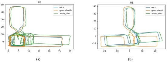
Figure 8.
Trajectories of the two methods on the dataset.

Table 2.
ATE and RTE for both methods.
Experiment and Analysis of Visual-Inertial Personnel Positioning
In order to verify the reliability of the improved algorithm, indoor and outdoor experimental scenarios are selected, and the underground space is simulated with indoor–outdoor experiments and tested several times. The localization device is placed on the wearable undershirt, the camera device is used, as shown in Figure 9. The experiments are conducted by pedestrians wearing the undershirt on outdoor roads and indoor hallways. The experimental comparison results and analysis are as follows:
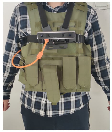
Figure 9.
Testers’ experimental wear chart.
(1) Outdoor playground experiment. The experimental scene was chosen as a school playground, and the experimenter walked around the playground wearing localization equipment. To verify the effectiveness of the algorithm, the VINS-fusion algorithm and the improved localization method were used for comparison. The localization trajectories of the two methods are shown in Figure 10 and Figure 11. The total length of the trajectory is 400 m, and the accuracy is calculated by the offset distance and the total distance traveled. The endpoint of the improved positioning method is very close to the starting point, the offset is about 1.997 m, and the positioning accuracy error is 0.50%. As for the results of the VINS-fusion algorithm run, the positioning was relatively accurate for a short distance after the start, but the drift was more serious after that. After one lap, the endpoint of the positioning trajectory seriously deviates from the starting point. The offset is about 25.67 m and the positioning accuracy error is 6.41%. Positioning error is reduced by 92.20%. The comparison shows that the method proposed improves positioning accuracy.
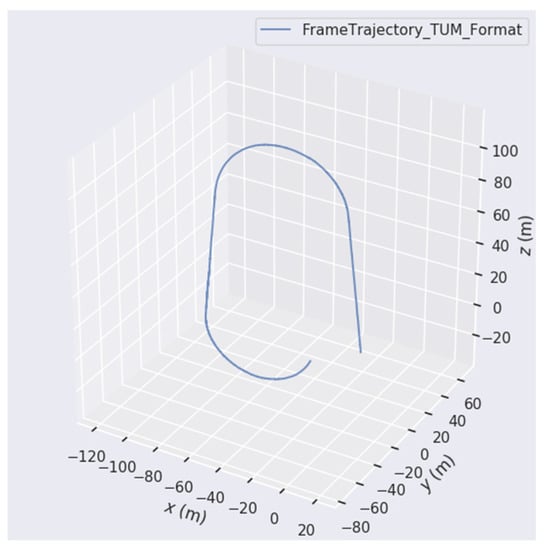
Figure 10.
VINS-fusion positioning trajectory map.
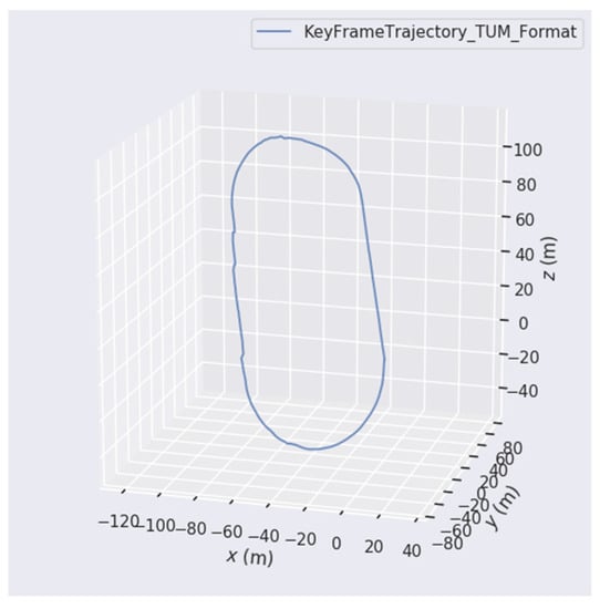
Figure 11.
Our algorithm positioning the trajectory map.
(2) Outdoor road experiment. The total length of the trajectory is 725 m, the offset is about 3.674 m, and the positioning accuracy error is 0.51%. The experimental trajectory is shown in Figure 12.
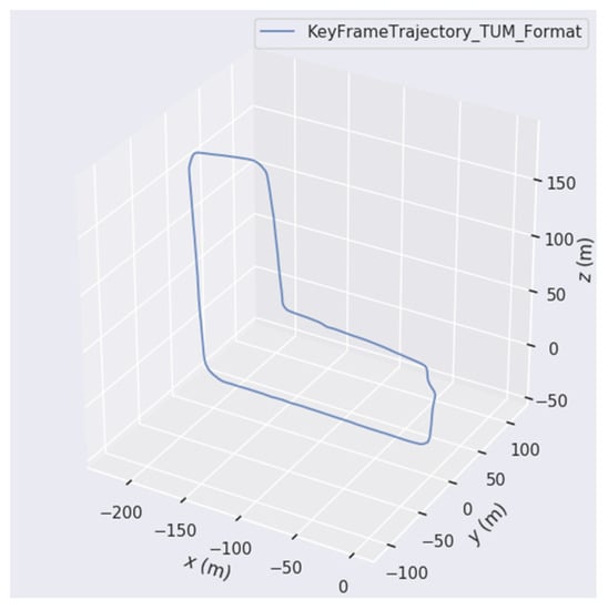
Figure 12.
Outdoor road positioning track map.
(3) Building experiment. Figure 13 shows the scene of the building. Experimenters wear positioning equipment along the building’s pre-determined trajectory from the starting point, back to the starting point after turning back into the building, that is, the starting point and the endpoint coincide, during which they have to pass up and down the stairs, the total length of the trajectory is 210 m, and the schematic diagram of the building experiment is shown in Figure 14. Figure 15 shows the positioning trajectory of the experimental run; from the running trajectory, the starting point and the starting point nearly coincide, the offset is about 0.983 m, and the positioning accuracy error is 0.47%.
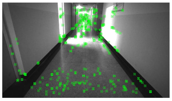
Figure 13.
Building environment point feature extraction.

Figure 14.
Building an experimental walking diagram.
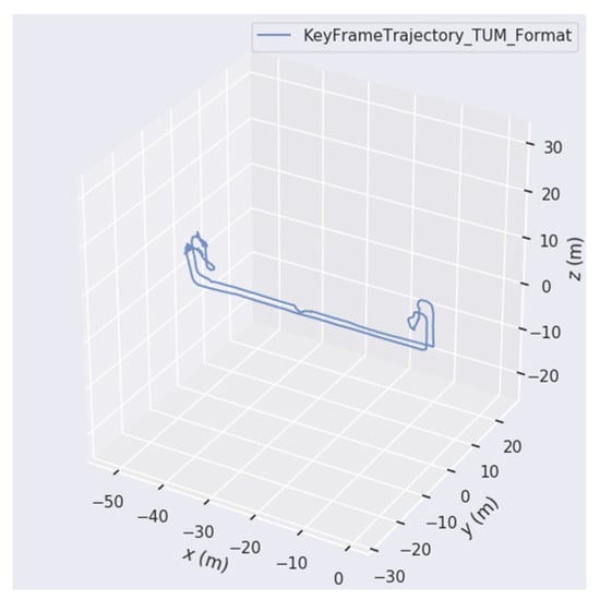
Figure 15.
Building positioning track map.
The positioning accuracy of the algorithm under the moving base was verified by indoor and outdoor experiments.
4. Conclusions
In this paper, a neural network-assisted visual-inertial personnel localization method is proposed. Our goal is to enhance the accuracy of conventional visual-inertial under a moving base by means of LSTM networks. We developed an inertial measurement error model based on inertial measurement under a moving base, generated ground truth trajectories with visual-inertial SLAM, and regressed 6-dimensional IMU data from IMU data fragments of the shaky base using a trained neural network. Then, the localization accuracy was improved by combining with visual. The proposed algorithm was experimentally proven to be effective in improving the positioning accuracy of people under a moving base.
The algorithm proposed in this paper mainly addresses the problem of low accuracy of person localization under a moving base, and the effect is not obvious for general scenes. Due to the small dataset and testers, the localization accuracy will be degraded for those who are not trained by the LSTM network. In addition, the scenes in underground spaces may be complex and multiple actions of testers may occur. Therefore, the follow-up work should increase the diversity of the data (adding testers and their possible actions) so that the proposed algorithm can be adapted to more complex environments.
Author Contributions
All named authors initially contributed a significant part to the paper. Conceptualization, Z.X. and Z.S.; methodology, Z.X.; software, Z.X.; validation, Z.X. and D.D.; formal analysis, Z.X.; investigation, Z.X. and D.D.; resources, Z.X. and D.D.; data curation, Z.X. and D.D.; writing—original draft preparation, Z.X.; writing—review and editing, Z.S.; visualization, Z.X.; supervision, Z.S.; project administration, Z.S.; funding acquisition, Z.S. All authors have read and agreed to the published version of the manuscript.
Funding
This research was funded by National Key R&D Program of China (Grant No. 2020YFC1511702, 2022YFF0607400), National Natural Science Foundation of China (61971048), Beijing Science and Technology Project (Z221100005222024), Beijing Scholars Program, Key Laboratory of Modern Measurement & Control Technology, Ministry of Education.
Institutional Review Board Statement
Not applicable.
Informed Consent Statement
Not applicable.
Data Availability Statement
Publicly available datasets were analyzed in this study. Code and data in the paper can be found here: https://github.com/zhengxu315755/LSTM-assisted-vi.git (accessed on 12 February 2023).
Conflicts of Interest
The authors declare no conflict of interest.
Abbreviations
The following abbreviations are used in this manuscript.
| UWB | Ultra Wide Band |
| IMU | Inertial Measurement Unit |
| WLAN | Wireless Local Area Network |
| PDR | Pedestrian navigation position projection |
| ZUPT | Zero Velocity Update |
| EKF | Extended Kalman Filter |
| SLAM | Simultaneous Localization and Mapping |
| MSCKF | Multi-State Constraint Kalman Filter |
| SVO | Semidirect Visual Odometry |
| VINS | Visual-Inertial SLAM |
| ORB | ORiented Brief |
| VIO | Visual Inertial Odometry |
| RIDI | Robust imu double integration |
| RoNIN | Robust Neural Inertial Navigation |
| ResNet | Residual Network |
| LSTM | Long short-term memory |
| MSE | Mean Square Error |
| ATE | Absolute Trajectory Error |
| RTE | Relative Trajectory Error |
| RMSE | Root Mean Square Error |
| SFM | Structure From Motion |
References
- Xu, S.; Wang, Y.; Sun, M.; Si, M.; Cao, H. A Real-Time BLE/PDR Integrated System by Using an Improved Robust Filter for Indoor Position. Appl. Sci. 2021, 11, 8170. [Google Scholar] [CrossRef]
- Lee, J.-S.; Huang, S.-M. An Experimental Heuristic Approach to Multi-Pose Pedestrian Dead Reckoning without Using Magnetometers for Indoor Localization. IEEE Sens. J. 2019, 19, 9532–9542. [Google Scholar] [CrossRef]
- Hou, X.; Bergmann, J. A Pedestrian Dead Reckoning Method for Head-Mounted Sensors. Sensors 2020, 20, 6349. [Google Scholar] [CrossRef] [PubMed]
- Zhao, T.; Ahamed, M.J. Pseudo-Zero Velocity Re-Detection Double Threshold Zero-Velocity Update (ZUPT) for Inertial Sensor-Based Pedestrian Navigation. IEEE Sens. J. 2021, 21, 13772–13785. [Google Scholar] [CrossRef]
- Bloesch, M.; Omari, S.; Hutter, M.; Siegwart, R. Robust visual inertial odometry using a direct EKF-based approach. In Proceedings of the 2015 IEEE/RSJ International Conference on Intelligent Robots and Systems (IROS), Hamburg, Germany, 28 September–3 October 2015; pp. 298–304. [Google Scholar] [CrossRef]
- Mainetti, L.; Patrono, L.; Sergi, I. A survey on indoor positioning systems. In Proceedings of the 2014 22nd International Conference on Software, Telecommunications and Computer Networks (SoftCOM), Split, Croatia, 17–19 September 2014; pp. 111–120. [Google Scholar] [CrossRef]
- Qin, T.; Shen, S. Robust initialization of monocular visual-inertial estimation on aerial robots. In Proceedings of the 2017 IEEE/RSJ International Conference on Intelligent Robots and Systems (IROS), Vancouver, BC, Canada, 24–28 September 2017; pp. 4225–4232. [Google Scholar] [CrossRef]
- Servières, M.; Renaudin, V.; Dupuis, A.; Antigny, N. Visual and Visual-Inertial SLAM: State of the Art, Classification, and Experimental Benchmarking. J. Sens. 2021, 2021, 2054828. [Google Scholar] [CrossRef]
- Hu, W.; Lin, Q.; Shao, L.; Lin, J.; Zhang, K.; Qin, H. A Real-Time Map Restoration Algorithm Based on ORB-SLAM3. Appl. Sci. 2022, 12, 7780. [Google Scholar] [CrossRef]
- Davison, A.J.; Reid, I.D.; Molton, N.D.; Stasse, O. MonoSLAM: Real-Time Single Camera SLAM. IEEE Trans. Pattern Anal. Mach. Intell. 2007, 29, 1052–1067. [Google Scholar] [CrossRef]
- Eade, E.; Drummond, T. Scalable Monocular SLAM. In Proceedings of the 2006 IEEE Computer Society Conference on Computer Vision and Pattern Recognition (CVPR’06), New York, NY, USA, 17–22 June 2006; Volume 1, pp. 469–476. [Google Scholar] [CrossRef]
- Mourikis, A.I.; Roumeliotis, S.I. A Multi-State Constraint Kalman Filter for Vision-aided Inertial Navigation. In Proceedings of the 2007 IEEE International Conference on Robotics and Automation, Roma, Italy, 10–14 April 2007; pp. 3565–3572. [Google Scholar] [CrossRef]
- Li, M.; Mourikis, A.I. High-precision, consistent EKF-based visual-inertial odometry. Int. J. Robot. Res. 2013, 32, 690–711. [Google Scholar] [CrossRef]
- Sun, K.; Mohta, K.; Pfrommer, B.; Watterson, M.; Liu, S.; Mulgaonkar, Y.; Taylor, C.J.; Kumar, V. Robust Stereo Visual Inertial Odometry for Fast Autonomous Flight. IEEE Robot. Autom. Lett. 2018, 3, 965–972. [Google Scholar] [CrossRef]
- Forster, C.; Zhang, Z.; Gassner, M.; Werlberger, M.; Scaramuzza, D. SVO: Semidirect Visual Odometry for Monocular and Multicamera Systems. IEEE Trans. Robot. 2016, 33, 249–265. [Google Scholar] [CrossRef]
- Qin, T.; Li, P.; Shen, S. VINS-Mono: A Robust and Versatile Monocular Visual-Inertial State Estimator. IEEE Trans. Robot. 2018, 34, 1004–1020. [Google Scholar] [CrossRef]
- Campos, C.; Elvira, R.; Rodriguez, J.J.G.; Montiel, J.M.M.; Tardos, J.D. ORB-SLAM3: An Accurate Open-Source Library for Visual, Visual–Inertial, and Multimap SLAM. IEEE Trans. Robot. 2021, 37, 1874–1890. [Google Scholar] [CrossRef]
- Alliez, P.; Bonardi, F.; Bouchafa, S.; Didier, J.-Y.; Hadj-Abdelkader, H.; Munoz, F.I.; Kachurka, V.; Rault, B.; Robin, M.; Roussel, D. Real-Time Multi-SLAM System for Agent Localization and 3D Mapping in Dynamic Scenarios. In Proceedings of the International Conference on Intelligent Robots and Systems, Las Vegas, NV, USA, 24–30 October 2020; pp. 4894–4900. [Google Scholar] [CrossRef]
- Kachurka, V.; Rault, B.; Munoz, F.I.I.; Roussel, D.; Bonardi, F.; Didier, J.-Y.; Hadj-Abdelkader, H.; Bouchafa, S.; Alliez, P.; Robin, M. WeCo-SLAM: Wearable Cooperative SLAM System for Real-Time Indoor Localization Under Challenging Conditions. IEEE Sens. J. 2021, 22, 5122–5132. [Google Scholar] [CrossRef]
- Ruotsalainen, L.; Kirkko-Jaakkola, M.; Rantanen, J.; Mäkelä, M. Error Modelling for Multi-Sensor Measurements in Infrastructure-Free Indoor Navigation. Sensors 2018, 18, 590. [Google Scholar] [CrossRef] [PubMed]
- Wang, Y.; Peng, A.; Lin, Z.; Zheng, L.; Zheng, H. Pedestrian Dead Reckoning-Assisted Visual Inertial Odometry Integrity Monitoring. Sensors 2019, 19, 5577. [Google Scholar] [CrossRef] [PubMed]
- Chai, W.; Li, C.; Zhang, M.; Sun, Z.; Yuan, H.; Lin, F.; Li, Q. An Enhanced Pedestrian Visual-Inertial SLAM System Aided with Vanishing Point in Indoor Environments. Sensors 2021, 21, 7428. [Google Scholar] [CrossRef] [PubMed]
- Dong, Y.; Yan, D.; Li, T.; Xia, M.; Shi, C. Pedestrian Gait Information Aided Visual Inertial SLAM for Indoor Positioning Using Handheld Smartphones. IEEE Sens. J. 2022, 22, 19845–19857. [Google Scholar] [CrossRef]
- Xiaoji, N.; Yan, W.; Jian, K. A pedestrian POS for indoor Mobile Mapping System based on foot-mounted visual–inertial sensors. Measurement 2022, 199, 111559. [Google Scholar] [CrossRef]
- Chen, C.; Lu, X.; Markham, A.; Trigoni, N. IONet: Learning to Cure the Curse of Drift in Inertial Odometry. In Proceedings of the AAAI Conference on Artificial Intelligence, New Orleans, LA, USA, 2–7 February 2018; Available online: https://ojs.aaai.org/index.php/AAAI/article/view/12102 (accessed on 14 November 2022).
- Yan, H.; Shan, Q.; Furukawa, Y. RIDI: Robust IMU Double Integration. In Proceedings of the European Conference on Computer Vision (ECCV), Munich, Germany, 8–14 September 2018; pp. 621–636. Available online: https://openaccess.thecvf.com/content_ECCV_2018/html/Hang_Yan_RIDI_Robust_IMU_ECCV_2018_paper.html (accessed on 14 November 2022).
- Herath, S.; Yan, H.; Furukawa, Y. RoNIN: Robust Neural Inertial Navigation in the Wild: Benchmark, Evaluations, & New Methods. In Proceedings of the 2020 IEEE International Conference on Robotics and Automation (ICRA), Paris, France, 31 May–1 August 2020; pp. 3146–3152. [Google Scholar] [CrossRef]
- Liu, W.; Caruso, D.; Ilg, E.; Dong, J.; Mourikis, A.I.; Daniilidis, K.; Kumar, V.; Engel, J. TLIO: Tight Learned Inertial Odometry. IEEE Robot. Autom. Lett. 2020, 5, 5653–5660. [Google Scholar] [CrossRef]
- Juarez-Salazar, R.; Zheng, J.; Diaz-Ramirez, V.H. Distorted pinhole camera modeling and calibration. Appl. Opt. 2020, 59, 11310–11318. [Google Scholar] [CrossRef]
- Graves, A. Long Short-Term Memory. In Supervised Sequence Labelling with Recurrent Neural Networks; Graves, A., Ed.; Springer: Berlin, Heidelberg, 2012; pp. 37–45. [Google Scholar] [CrossRef]
- Paszke, A.; Gross, S.; Massa, F.; Lerer, A.; Bradbury, J.; Chanan, G.; Killeen, T.; Lin, Z.; Gimelshein, N.; Antiga, L.; et al. PyTorch: An Imperative Style, High-Performance Deep Learning Library. Adv. Neural Inf. Process. Syst. 2019, 32, 8024–8035. Available online: https://proceedings.neurips.cc/paper/2019/hash/bdbca288fee7f92f2bfa9f7012727740-Abstract.html (accessed on 17 November 2022).
Disclaimer/Publisher’s Note: The statements, opinions and data contained in all publications are solely those of the individual author(s) and contributor(s) and not of MDPI and/or the editor(s). MDPI and/or the editor(s) disclaim responsibility for any injury to people or property resulting from any ideas, methods, instructions or products referred to in the content. |
© 2023 by the authors. Licensee MDPI, Basel, Switzerland. This article is an open access article distributed under the terms and conditions of the Creative Commons Attribution (CC BY) license (https://creativecommons.org/licenses/by/4.0/).