Abstract
Research on space docking technology was first motivated by the application scenario of space station docking in the aviation field. Due to the maturity of this technology, its application field is expanding to other industries. To benefit the intelligent transportation field, this study uses space docking technology to realize combination and reconstruction between car bodies. Different spatial docking methods and structural characteristics are determined by different application scenarios. The docking of the space station is completed in the suspended state of the body in the outer space environment, which requires advanced technology, is high in hardware cost, and involves a small channel diameter. In this study, the docking of the reconstructed vehicle is completed on the ground; thus, it is low in hardware cost and involves a large channel diameter. Based on the above technical requirements, a three−point circular peripheral docking method is designed for the reconstructed vehicle. A visual positioning system is built, the mapping relationship between the camera coordinate system and the landmark coordinate system rotation matrix and translation vector is established, and the adaptive capture behavior is realized by path planning through the inverse pose solution model. Simulation experiments demonstrate that the active and passive vehicle bodies can achieve compliance capture with small collision force under the two conditions of forward collision and oblique collision, and the recovery coefficient after collision and docking is in the range of (0, 0.01). The acceleration decay process under two working conditions is measured in the crash test of a sample vehicle, which verifies the feasibility of the space reconstruction of the vehicle docking mechanism and the ability of this configuration to achieve tasks, providing a constructive idea for space docking technology with a large channel diameter.
1. Introduction
In the era of intelligent manufacturing development, research on space docking technology is expanding into many fields, including intelligent transportation, aviation, offshore operation, and intelligent machinery. Overall reconstruction of space docking, which is accomplished by location, capture, and rigid connection, is the precondition required to achieve space assembly and space expansion [1,2,3,4,5]. Taking the reconstructed automobile as the research object, the docking process is divided into four steps: (1) the target vehicle’s positioning is observed, pose parameters are estimated, and capture path is planned; (2) the capture phase is prepared when the active vehicle is close to the target vehicle; (3) the target vehicle is brought into contact with the active vehicle to accomplish initial collision; (4) after capture energy consumption and control of vibration stability are accomplished, docking is achieved [6,7,8,9,10].
In recent years, new docking technology and mechanisms have been jointly studied by transportation research institutes and intelligent robot research institutions. Autonomous teleoperation of dual−arm robots was designed by David of Milan Polytechnic University. Unobstructed servo was accomplished during docking [11]. A dynamic model of a colliding body was established by means of the second kind of Lagrangian method and the Newton–Euler method by Dong Qiuhuang of Fuzhou University. An augmented robust control algorithm was designed to stabilize the unstable combinatorial system after a collision [12]. A dynamic model of attitude coupling problems for structures composed of spatial rigid rods and springs was established by Yin Tingting of Northwestern Polytechnical University. The coupling dynamic effects of the simplified model were analyzed using the symplectic geometry method, which aims to provide real−time dynamic response results for feedback control of super large space structures [13]. An electro−permanent magnetic docking/separation mechanism was designed by Xu Zhen of the Chinese Academy of Sciences that integrated the electromagnetic and permanent magnetic characteristics, which solved the problems of small coupling force and high energy consumption in the electromagnetic docking mode [14]. A flexible electromagnetic valve docking mechanism was designed by Marco Buonomo et al. in Jerusalem, Israel. The docking system experiment was established by the traction of microgravity test [15]. The frontend robotics enabling near−term demonstration (FREND) dobby space system, which is used for target acquisition and refurbishment, was researched by Debus et al. in Reston, VA, USA [16]. A small docking mechanism adopting a semi−androgynous deformation geometry structure was researched by Lorenzo et al. of the University of Padua. A simulation experiment showed that the port can realize 5° or 15 mm relative dislocation docking [17]. An optimization model was established for the kinematic performance and force transmission performance of the integrated docking mechanism by Zhang Lingxuan of the Shanghai Key Laboratory of Space Vehicle Organization. This optimization model provides a reference for the design and technical application of the weak impact docking mechanism [18]. The 3UPS−PS (U—universal joint pair; P—prismatic pair; S—spherical hinge) parallel mechanism was researched to improve the weak impact space docking experiment by Xie Zenghui of the Harbin Institute of Technology, and it was shown to solve the problems related to force signal filtering and pose measurement of the docking ring [19]. A dynamic synthesis correction method of deviation was proposed in the application scenario of docking assembly for the aircraft wing−fuselage based on a laser tracker and machine vision by Zhu Yongguo of Nanchang Hangkong University, and it effectively improved the quality of butt joint assembly [20]. The region segmentation method was applied to compress the number of point clouds and reconstruct the image butt flange for the application of the ship shafting automatic butt joint system to improve the assembly efficiency by Lei Pan of Huazhong University of Science and Technology [21]. A visual automatic docking method based on heterogeneous equipment was proposed by Zha Qingshan of Nanchang Aviation University. Using a laser tracker and industrial camera for data fusion, the docking method was able to monitor the docking process and improve the docking quality [22]. A fast positioning method based on deep learning and binocular vision was proposed for docking mechanisms. Simulation results showed that the average error of the docking process was less than the capture radius and met the docking requirements [23]. Yu Kun of Harbin University of Technology proposed both a monocular vision navigation method based on the shortest path to describe the calculation model of capture point parameters, as well as an including the segmentation, selection, and combination of contours in images to solve the contour extraction problem of docking rings in complex images. Simulation results showed that the proposed method was accurate and stable to the acquisition point [24]. A high−precision line−of−sight angle measuring system was developed by Feng Zhihui of the Chinese Academy of Sciences to realize intersection and docking of vehicles [25]. The overall coordinate system model of the double optical path based on laser transmission was established by Wang Guang of the Chinese Academy of Sciences. In the experiment, fast and accurate docking with an error value less than 2 was achieved [26]. A vision system was designed by Chen Lu of Northwestern Polytechnical University for the capture process. The system used four charge−coupled device (CCD) cameras, among which two had a 20° field of view to detect distant targets, and the other two had a 40° field of view for detecting close range targets [27]. The relative posture was determined between the artificial landmark and the camera according to the perspective three−point (P3P) visual positioning method. The guidance signs of the docking target were collected by the vehicle monocular vision system [28]. An autonomous rendezvous and docking mechanism combining electromagnetic technology and a “pen cap” docking mechanism was designed by Mu Zhongcheng of Shanghai Jiao Tong University, and it can serve as a reference for the calibration of far−field models [29]. The matching degree was evaluated by Yu Kun of the Harbin Institute of Technology based on contour direction features, and the target pose parameters were solved from the optimal matching results to achieve the target navigation requirements of space docking [30].
The studies mentioned above focused on the accuracy and energy loss analysis of the docking process. However, there is great demand to expand the reconstruction space of the docking mechanism while ensuring a lightweight structure and low cost. Furthermore, the maximum diameter of the docking body channel is only about 800 mm, which limits space expansion and interworking; thus, the channel diameter, structure weight, and cost need to be optimized.
In this study, the “three−point circle peripheral cone” car body reconstruction technology is proposed to realize large space reconstruction and driving mode switching between the twin mini car and the single car based on cost control, aiming at the demand for space reconstruction of intelligent automobiles. The process of double mini car integration is studied with a large tolerance and a weak collision in a short distance during its dynamic deceleration. The visual positioning capture control algorithm is focused upon in the space docking process. Dynamic and static research and experiments are conducted on the docking mechanism. The reconstructed vehicle model is shown in Figure 1.
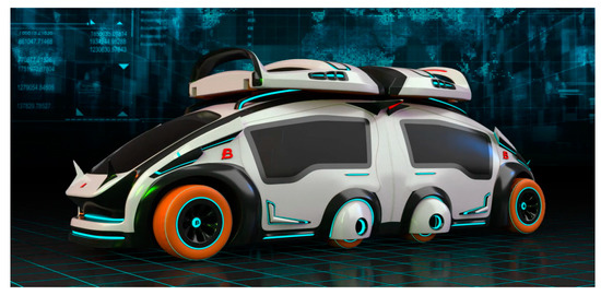
Figure 1.
Reconstructed vehicle model.
2. Structural Design
2.1. Structural Principle
In the process of double car docking, the target car body is tracked by the active car body based on the visual positioning system, using the “three−point circle peripheral ring cone” space docking technology to complete the posture adjustment and weak collision docking process. The space docking frame model is shown in Figure 2. The active and passive car bodies are the same in appearance and space dimensions, but the difference is in the docking part. Three holes are arranged on the rear frame of the active and passive car body. The three holes of the active car are called fine pupil Dr1, Dr2, and Dr3, as shown in the green part of Figure 3. And the three holes of the passive car are called lock body Pa1, Pa2, and Pa3. The top left and right hole positions Dr2 and Dr3 (or Pa2 and Pa3) take the bottom hole position Dr1 (Pa1) as the center, as shown in the red line of Figure 3. The docking process is shown in Figure 3. With the help of vision, the driven car’s circle center of lock body Pa1 is looked for by the driving car’s circle center of fine pupil Dr1. When they are aligned, the lock tongue is triggered to be inserted deep into lock body Pa1, adjusting the position and posture through the suspension of the active vehicle (Figure 4). Then, the top two fine pupils (Dr2 and Dr3) rotate with the center to find the corresponding lock body hole (Pa2 and Pa3) and trigger the lock tongue after aligning with the magnetic suction mechanism. The three holes are locked at the same time to complete the butt joint.
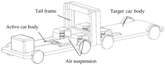
Figure 2.
Space docking car body model.
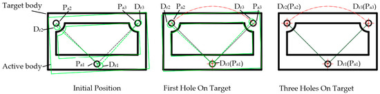
Figure 3.
Three−point circle and ring−cone type docking principle.
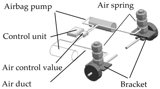
Figure 4.
Suspension structure model.
2.2. Structural Transmission System Design
The butt joint of the chassis is mainly completed by the transmission torsion bar through screw locking, as shown in Figure 5. The two front and two rear wheels of the integrated vehicle are steering wheels. When the steering wheel is turned, the front and rear wheels deflect in opposite directions to achieve vehicle steering and maintain a small turning radius. As shown in Figure 6, the wheelbase L is 2150 mm, the distance S from the middle wheel to the tail frame is 450 mm, the value range of the deflection angle of the outer steering wheel is [30°, 40°], the maximum deflection angle is 40°, and the minimum turning radius of the vehicle calculated according to the Ackermann steering geometry is 3489 mm. It is lower than the current minimum turning radius of traditional minivan, which is 4500 mm.
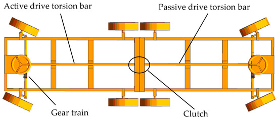
Figure 5.
Model of chassis dock structure.
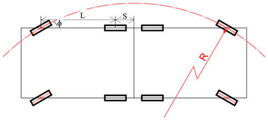
Figure 6.
Turning radius of the whole vehicle.
3. Visual Positioning System
3.1. System Design
Reconstructed vehicles may need to dock in both outdoor unobstructed environments and indoor environments such as an underground garage. For indoor docking environments, traditional GPS (Global Positioning System) navigation and positioning cannot be used due to building occlusion. At present, the main options are wireless positioning, laser Simultaneous Localization and Mapping (SLAM), visual SLAM, and landmark positioning. Wireless positioning often yields poor location accuracy due to multi−path interference. Laser SLAM technology is mature and has high precision, but its cost is high and its dynamic interference resistance is weak. Visual SLAM uses cameras to track visual features, and it has a low cost and strong adaptability, but low reliability. Landmark positioning utilizes natural and artificial landmarks, such as road signs, for positioning. Natural landmarks have good universality, but their computation is complex and not robust. In contrast, artificial landmarks are relatively simple to calculate and stable in their characteristics. However, the frequently used RFID (Radio Frequency Identification) tags and magnetic strip landmarks have a short working distance, limited fixed route movement, and poor flexibility.
To avoid the above shortcomings, in this study, a robot positioning system based on vision is adopted for the reconstructed car to provide artificial beacons for indoor mobile positioning of the reconstructed car, achieving accurate and stable docking.
The visual positioning system is composed of an artificial beacon, a visual module, and an embedded image processing platform. The beacon is made of infrared luminous material and is placed above the three locking holes of the passive vehicle. The infrared camera is embedded in the active vehicle body. The vision module is responsible for automatic exposure control and image data acquisition, and it sends the image to the processor module through the EPPI (Enhanced Parallel Peripheral Interface). The processor module is the core part of the whole system, and is responsible for receiving the image data sent by the camera module, running the automatic exposure control algorithm and artificial beacon recognition algorithm, and outputting the final detection results to the actuator through the serial port for graphic comparison and movement. Figure 7 shows the working principle of the visual positioning system.

Figure 7.
Working principle of the visual positioning system.
3.2. Modules and Algorithms
The main body of the algorithm for the reconstructed vehicle visual positioning system is composed of the following parts: image preprocessing, distortion correction, label feature extraction, label combination clustering, label identification, and label position calculation. The software includes a camera imaging module, a visual image preprocessing module, a tag detection and recognition algorithm module, and a tag position information calculation module.
Tag image acquisition is realized with the camera imaging module, which is composed of the OV2640 optical chip and the Omni Visio lens. The road sign position identification label is composed of three marking points, which are fixed above the three locking holes of the passive rear frame. The location tag is surrounded by the identification tag, as shown in Figure 8. The principle is to ensure that there are no blind areas in the moving range of the active vehicle body during the docking process. The infrared light source of the driving car adopts near−infrared light and an 850 nm light−emitting diode. To reduce the interference pixels of ambient visible light, a narrowband filter (corresponding band) is set in front of the camera lens to ensure that only the artificial beacon is imaged. Image processing, i.e., binary processing, is carried out after road signs are collected. Feature extraction of the marked points in the binary image is performed, and then, the clustering processing is carried out to calculate the tag combination. Finally, according to the triangle formed by three marker points, the identity information of the label is extracted. The position and azimuth of the camera relative to each tag’s coordinate system are calculated by the tag position information calculation module. The label coordinate system that identifies the marked points according to the three positions is called the landmark coordinate system. To calculate the relative relationship between the camera coordinate system and the landmark coordinate system, the rotation matrix and translation matrix between the two coordinate systems are derived.
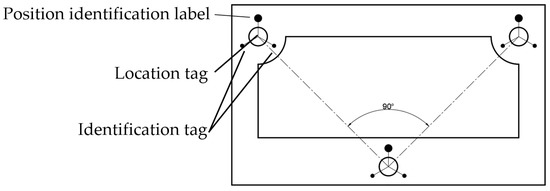
Figure 8.
Identification of location.
First, the camera coordinate system and landmark coordinate system are established, as shown in Figure 9. The origin of the active car body’s camera coordinate system is the intersection of the optical axis of the camera and the light−sensitive chip, which is located at the point Od above the fine pupil of the tail frame of the active vehicle body, where the X−axis is the OdAd connection, the Y−axis is the OdBd connection, and the Z−axis is the direction along the optical axis outward, pointing to the target vehicle body. The camera coordinate system (active car body) is OdXdYdZd. There are three marking points, Op (lower center), Ap (upper left side), and Bp (upper right side), above the three lock bodies of the target car body tail frame. The origin of the landmark coordinate system is the marking point Op of the lowest center. The OpAp connection is in the X direction, the OpBp connection is in the Y direction, and the vertical outward direction is in the Z direction. The landmark coordinate system (target car body) is OXpYpZp. The location coordinates of the three marked points of OAB are (0,0,0), (L,0,0), and (0,L,0), and L is the distance of OA. Mapping relationship of camera coordinate system and guide coordinate system is shown in Figure 10.
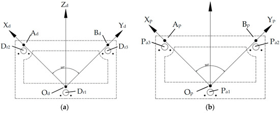
Figure 9.
Establishment of coordinate systems. (a) Camera coordinate system. (b) Landmark coordinate system.
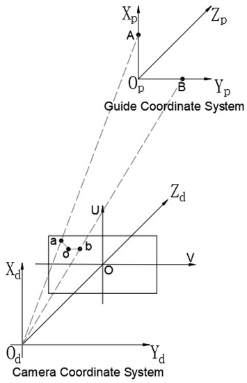
Figure 10.
Mapping relationship of camera coordinate system and guide coordinate system.
It is assumed that the pixel coordinates of the point p under the image coordinate system are (u, v), and the coordinates of the point under the camera coordinate system are (xd, yd, zd), satisfying the following equation:
The matrix M1 represents the camera internal parameter matrix.
Rigid transformation between the camera coordinate system and the landmark coordinate system is completed using the rotation matrix R and the translation vector t. The equation is as follows:
The rotation matrix R and the translation vector t are unknown quantities to be solved, and M2 represents the transformation parameter matrix of the camera coordinate system and landmark coordinate system.
Substituting Equation (2) into Equation (1) yields
It is assumed that the coordinates of the location identification marking points O, A, and B under the landmark coordinate system are (xpi, ypi, zpi) (i = 1, 2, 3), and the image coordinates are (ui, vi) (i = 1, 2, 3). Substituting these coordinates into Equation (3) yields three equations:
Then, the optimization algorithm is used to solve the rotation matrix R and the translation vector t, and the coordinate of the target vehicle’s landmark coordinate system’s origin under the camera coordinate system of the active vehicle is calculated as t, while the coordinate of the camera coordinate system’s origin of the active vehicle under the target vehicle landmark coordinate system is −RTt.
4. Dynamic Simulation Analysis
The capture behavior is triggered by the control system, according to the above optimization calculation process of the visual positioning system. Due to the different driving positions and postures of the active vehicle and the target vehicle, and the difference of the initial conditions of the docking vehicle body, the catching ability and buffering process of the reconstructed vehicle body’s docking structure under different working conditions are different. In this study, two different working conditions are set for the space docking process. The dynamic simulation of the “three−point circle peripheral cone” docking method is carried out, and then, the kinetic energy changes of the active and passive car bodies during the docking process as well as the force changes of the key parts of the docking mechanism are analyzed. The dynamic simulation analysis is carried out using Automatic Dynamic Analysis of Mechanical Systems (ADAMS) software. The working condition parameter settings are shown in Table 1.

Table 1.
Initial Condition Parameters of Space Docking System.
4.1. Simulation Analysis of the Positive Docking Process
The positive docking process of Condition 1 in Figure 11a indicates that, as the docking rod completely penetrates into the target body, the active vehicle successfully captures the target vehicle and completes the docking task. The simulation results of the docking processes of the two vehicles under Condition 1 are shown in Figure 11b. The target vehicle is represented by the red curve (CHE1), and the active vehicle is represented by the blue curve (CHE2). The simulation results show that when the active vehicle decelerates to approach the target vehicle, the kinetic energy decreases by 77.8%, from 2.35 N·m to 0.52 N·m. During the docking process of the docking rod, the kinetic energy oscillation of the driving vehicle rises to 0.57 N·m. After the docking rod contacts the docking hole, the kinetic energy decreases from 0.57 N·m to 0.25 N·m, and after correction, the kinetic energy approaches 0.15 N·m and tends to be stable. The kinetic energy of the active vehicle decreases by 93.6% in total. During deceleration upon approach, the total kinetic energy of the system decreases from 4.5 N·m to 0.6 N·m, which is an 86.6% decrease. After the docking rod contacts the docking hole, the kinetic energy decreases from 0.8 N·m to 0.3 N·m. After correction, the kinetic energy approaches 0.25 N·m and tends to be stable. The total kinetic energy of the system decreases by 94.4%, as shown in Figure 11c. The maximum force on the butt bar for alignment is about 900 N, and the duration is relatively short, at about 0.2 s. The force on the connecting rod stabilizes at about 50 N, as shown in Figure 11d. The maximum reaction force during vehicle body docking is about 2300 N, as shown in Figure 11e. According to the relative speed change between the active vehicle and the target vehicle, the coefficient of restitution S of the vehicle body after the initial collision is about 0.68, and the coefficient of restitution S after two contact collisions is about 0, as shown in Figure 11f. The coefficient of restitution S refers to the ratio of the normal relative separation speed and the normal relative approach speed of the two car bodies at the contact point before and after the collision, expressed as follows:
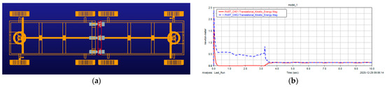
Figure 11.
Simulation results of Condition 1. (a) Top view of docking car body under Condition 1. (b) Kinetic energy curve of D−vehicle and T−vehicle. (c) Total kinetic energy of system. (d) F−situation of the D−vehicle’s docking rod in advancing process. (e) Vehicle body collision counteracts the stress condition. (f) Change of relative speed between D−vehicle and T−vehicle.
V1 and V2 represent the speed of the active and target vehicles before the collision, and and represent the speed of the active and target vehicles after the collision.
4.2. Simulation Analysis of the Oblique Docking Process
Figure 12a shows the inclined 3° docking process under Condition 2, indicating that the active vehicle successfully captures the target vehicle and completes the docking task. The oscillation period about the change in kinetic energy is slightly longer than that in Condition 1, as shown in Figure 12b. The change of the total kinetic energy of the system during deceleration upon approach is similar to that under Condition 1, as shown in Figure 12c. The maximum force on the connecting rod of the driving car is about 500 N in the process of moving forward, and the duration is slightly longer than that of Condition 1, at about 0.5 s. The force on the connecting rod stabilizes at about 50 N, but the amplitude of oscillation is slightly larger, as shown in Figure 12d. The reason is that the collision position is tilted. The maximum counteracting force of the buffer device of the docking mechanism oscillates in the amplitude range of 1700−3000 N and finally becomes stable at about 2250 N, as shown in Figure 12e. According to the relative speed change between the active vehicle and the target vehicle, the coefficient of restitution S after the initial collision of the vehicle body is about 0.52, and the coefficient of restitution S after two contact collisions is about 0.01, as shown in Figure 12f.
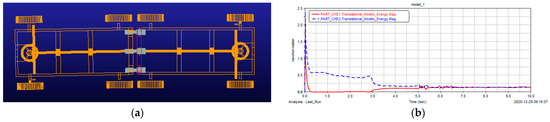
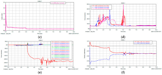
Figure 12.
Simulation results of Condition 2. (a) Top view of docking car body under Condition 2. (b) Kinetic energy curve of D−vehicle and T−vehicle. (c) Total kinetic energy of system. (d) F−situation of the D−vehicle’s docking rod in advancing process. (e) Vehicle body collision counteracts the stress condition. (f) Change of relative speed between D−vehicle and T−vehicle.
5. Experimental Analysis
5.1. Hardware Equipment
The reconstructed sample vehicle weighs about 100 kg, adopts double wishbone suspension for vibration reduction, and has four−wheel drive, as shown in Figure 13. The drive motor is an Oniki DC servo motor. The drive motor is built into the car body and is driven by a synchronous belt and a universal joint. The tires are golf cart tires with a radius of 160 mm. They are durable and reliable with a large contact area. Gyroscopes are installed inside, which can collect lateral acceleration (X), longitudinal acceleration (Y), vertical acceleration (Z), and changes of some angles of the whole vehicle in real time. The body orientations of the three accelerations are shown in Figure 14. Four motor drivers rotate the motor to realize the moving, retreating, steering, and local rotation of the vehicle.
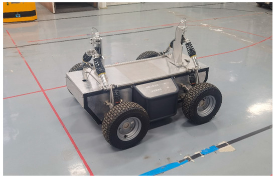
Figure 13.
Photo of sample vehicle.
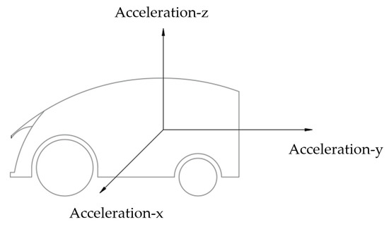
Figure 14.
Car body acceleration diagram.
5.2. Data Transmission
The wireless module is used for data transmission. The main controller of the vehicle collects and sends the data of the gyroscope to the computer through the wireless module, and then, the serial assistant prints the data. The receiving frequency is 0.02 Hz.
5.3. Experimental Data
Like the dynamic simulation, the experiment is also conducted for two working conditions. The changes of kinetic energy and force during collision are determined in the dynamic simulation, whereas acceleration is measured by the gyroscope of the reconstructed sample vehicle in the experiment. Both kinetic energy and force are parameters related to acceleration; thus, it is sufficient to record and study the acceleration, as shown in Figure 15.
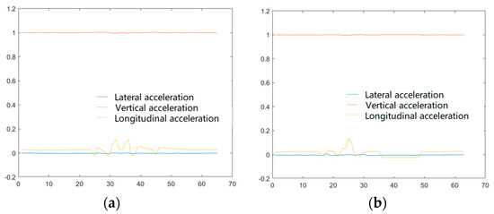
Figure 15.
Acceleration variation diagram during collision. (a) Condition 1. (b) Condition 2.
Under the premise of driving at a minimum speed of 0.2 m/s, the collision and docking test is conducted for the car bodies. First, under the working condition of 0° in the vertical direction of the body, the acceleration of the driving car after the first and second collisions is only 0.1 m/s2. Under the action of the magnetic suction system, the interval between the two collisions is 3.5 s. Then, the acceleration rapidly drops to 0.03 m/s2, entering the micro vibration stage that lasts about 8 s and achieves near−zero stability. Second, under the working condition of 3° in the vertical direction of the vehicle body, the acceleration of the driving car after the first collision is only 0.12 m/s2, and then, it directly enters the micro vibration stage to achieve near−zero stability.
6. Discussion
Reconstructed vehicles can be successfully docked under different working conditions, with a short docking cycle, high accuracy, and good stability. Compared with the straight working condition, the car body has a shorter reconstruction period and better stability under the slightly inclined working condition due to its faster angular energy consumption. The experiment proves that the three−point circle peripheral cone vision system can complete the reconstruction task of active and passive vehicle bodies and finally achieve the integrated driving of the whole vehicle. From the comparison of the results of the sample vehicle test and the simulation test, the interval times of the second collision are 3.5 s and 2 s, respectively, which are relatively close. The cause of the deviation is the friction coefficient and magnetic attraction system.
7. Conclusions
According to the visual positioning algorithm and dynamic simulation analysis of the space reconstruction vehicle docking mechanism, the following conclusions can be drawn. The “three−point circle peripheral ring cone” space docking mechanism can successfully capture the target vehicle body. The total kinetic energy of the system in Condition 2 is similar to that in Condition 1. According to the different initial conditions of docking, the force on the docking rod of the driving car under oblique collision in Condition 2 is significantly less than that under normal collision in Condition 1. The friction coefficient of the docking mechanism has a significant influence on the collision force in the process of vehicle reconfiguration under conditions other than the normal collision. After the butt link first hits the target pin groove, there are still 2 s of feeding time before the locking correction period begins. At this time, the pin is still under force, but the moment is still very small due to small deflection angle, and it has little impact on the capture. The “three−point circle peripheral ring cone” space docking mechanism can well consume the system kinetic energy in the docking process and smoothly achieve the target vehicle capture. The kinetic energy of the active vehicle and the target vehicle decreases by about 87% after the initial collision, and the final system kinetic energy decreases by about 95% after stabilization, which can meet the design requirements. According to the change of the relative speed between the driving vehicle and the target vehicle after the initial collision, the recovery coefficient of Condition 2 is less than that of Condition 1, which shows that the frontal collision has relatively weak capture and buffering capacity. Under the oblique collision condition, the cone guidance of the docking mechanism plays a significant role in the final capture.
8. Patents
Lin Xi. A dual−drive and dual−configuration space reconfigurable vehicle: China, 2021106233039[P].2021−7−23.
Author Contributions
Conceptualization, L.X.; methodology, L.X. and H.N.; software, Z.L.; validation, L.X.; formal analysis, L.X.; investigation, C.Z.; resources, B.W.; data curation, L.X.; writing—original draft preparation, L.X. and H.N.; writing—review and editing, L.X.; visualization, H.N.; supervision, B.W.; project administration, L.X.; funding acquisition, L.X. All authors have read and agreed to the published version of the manuscript.
Funding
This study was supported by the Open Research Fund of Anhui Engineering Technology Research Center of Automotive New Technique (No. QCKJ202006); the Enterprise entrusted scientific research project of Anhui Polytechnic University (No. HX−2021−12−143); the 2022 Anhui Polytechnic University−Jiujiang District University Student Entrepreneurship Support Special Fund Project−Key innovation project; Scientific Research Project of Universities in Anhui Province (No.2022AH050982); Start−up Fund for the Introductions of AHPU (No.2022YQQ001); and National Natural Science Foundation Youth Program of China (No.12205004).
Conflicts of Interest
The authors declare no conflict of interest.
References
- Zhang, C.; Liu, Z. Review of space docking mechanism and its technology. Aerosp. Shanghai 2016, 33, 1–11. (In Chinese) [Google Scholar]
- Chen, M.; Xiao, Y.; Zhang, T. Artificial intelligence technology in space servicing and manipulation. Manned Spacefl. 2018, 24, 285–291. (In Chinese) [Google Scholar]
- Sun, J.; Tian, Q.; Hu, H. Advances in dynamic modeling and optimization of flexible multibody systems. Chin. J. Theor. Appl. Mech. 2019, 51, 1565–1586. (In Chinese) [Google Scholar]
- Shen, X.; Zeng, L.; Jin, Y.; Zhang, Q. Status and prospect of on−orbit assembly technology. Manned Spacefl. 2017, 23, 228–235. (In Chinese) [Google Scholar]
- Floresabad, A.; Ma, O.; Pham, K.; Ulrich, S. A review of space robotics technologies for on−orbit servicing. Prog. Aerosp. Sci. 2014, 68, 1–26. [Google Scholar] [CrossRef]
- Zhao, J. Research on Visual Simulation System of Docking Process of Replenishment at Sea; Jiamusi University: Jiamusi, China, 2017. [Google Scholar]
- Wang, W.; Yang, J. Spacecraft Docking & Capture Technology: Review. J. Mech. Eng. 2021, 57, 215–231. [Google Scholar]
- Parma, G. Overview of the NASA docking system and the international docking system standard. In Proceedings of the AIAA Annual Technical Symposium, Houston, TX, USA, 20 May 2011. [Google Scholar]
- Ma, S.; Feng, X.; Kong, N.; Zhou, L.; Zhu, Z. Review and development prospect of space rendezvous and docking mechanism. J. Rocket. Propuls. 2022, 48, 1–15. [Google Scholar]
- Wu, H.; Li, Y.; Jiang, Y.; Zhou, Z. Summary of AUV underwater recycle docking technology. J. Harbin Eng. 2019, 40, 1–11. [Google Scholar]
- Nicolis, D.; Palumbo, M.; Zanchettin, A.M.; Rocco, P. Occlusion−free visual servo for the shared autonomy teleoperation of dual−arm robots. IEEE Robot. Autom. Lett. 2018, 3, 796–803. [Google Scholar] [CrossRef]
- Dong, Q.; Chen, L. Impact dynamics simulation and robust control for stabilizing of a space manipulator capturing satellite. Chin. J. Comput. Mech. 2014, 3, 315–321. (In Chinese) [Google Scholar]
- Yin, T.; Deng, Z.; Hu, W.; Li, Q.; Cao, S. Dynamic modelling and simulation of orbit and attitude coupling problems for structure combined of spatial rigid rods and spring. Chin. J. Theor. Appl. Mech. 2018, 50, 87–98. (In Chinese) [Google Scholar]
- Xu, Z.; Lin, M.; Li, J.; Zhang, B.; Mao, Q.; Yan, A. Design of docking/separation mechanism based on permanent magnet technology. Aerosp. Shanghai (Chin. Engl.) 2021, 38, 128–135. [Google Scholar]
- Petrillo, D.; Buonomo, M.; Cavinato, A.; Chiariotti, F.; Gaino, M.; Branz, F.; Olivieri, L.; Sansone, F.; Francesconi, A.; Borst, G. Flexible electromagnetic leash docking system experiment from design to microgravity testing. In Proceedings of the 66th International Astronautical Congress, IAC−15, Jerusalem, Israel, 12–16 October 2015; pp. 1–12. [Google Scholar]
- Debus, T.J.; Dougherty, S.P. Overview and performance of the frontend robotics enabling near−term demonstration (FREND) robotic arm. In Proceedings of the AIAA Infotech@Aerospace Conference, Seattle, DC, USA, 6–9 April 2009; AIAA: Reston, VA, USA, 2009. AIAA 2009−1870. [Google Scholar]
- Lorenzo, O.; Alessandro, F. Design and test of a semi androgynous docking mechanism for small satellites. Acta Astronaut. 2016, 122, 219–230. [Google Scholar]
- Zhang, L.; Shao, J.; Zhou, H.; Zhang, C. Analysis and optimization of force transmissibility and kinematic performance of low impact docking mechanism. Manned Space Flight 2015, 21, 462–467. (In Chinese) [Google Scholar]
- Xie, Z. Research on the Low Impact Space Docking Mechanism and Active Compliant Control. Master’s Thesis, Harbin Institute of Technology, Harbin, China, 2017. (In Chinese). [Google Scholar]
- Zhu, Y.; Zhang, W.; Deng, Z.; Liu, C. Dynamic Synthesis Correction of Deviation for Aircraft Wing−fuselage Docking Assembly Based on Laser Tracker and Machine Vision. J. Mech. Eng. 2019, 55, 187–196. [Google Scholar]
- Lei, P.; Li, W.; Li, T.; Liu, F.; Liu, C. Research and Development of Automatic Docking System of Ship Shafting Based on 3D. Editor. Off. Ship Build. China 2021, 192–201. [Google Scholar]
- Zha, Q.S.; Zhu, Y.G.; Zhang, W.B. Visual and automatic wing−fuselage docking based on data fusion of heterogeneous measuring equipments. J. Chin. Inst. Eng. 2021, 44, 792–802. [Google Scholar] [CrossRef]
- Zhang, Y.; Ai, J. Positioning of aerial refueling drogue and docking control based on binocular vision. Chin. Inst. Electron. 2021, 2940–2953. [Google Scholar]
- Kun, Y.; Mingyu, C.; Jiajia, D.; Xiangyu, L. Monocular visual navigation method for capture point of docking ring. Chin. J. Sci. Instrum. 2018, 228–236. [Google Scholar]
- Feng, Z.; Yue, Y.; Dai, D.; Yuan, L.; Nan, Y. High precision line−of−sight angle measuring and large ranging laser radar system for deep−space rendezvous and docking. Appl. Opt. 2020, 59, 10565–10573. [Google Scholar] [CrossRef]
- Wang, G.; Gao, Y.; Ma, Y.; Xue, X.; Zhang, W.; Shao, S. High accurate docking technology of laser and theodolite. Chin. Soc. Astronaut. 2018. [Google Scholar]
- Chen, L.; Huang, P.; Cai, J.; Meng, Z.; Liu, Z. A non−cooperative target grasping position prediction model for tethered space robot. Aerosp. Sci. Technol. 2016, 58, 571–581. [Google Scholar] [CrossRef]
- Li, X.; Liang, X.; Jia, S.; Li, M. Visual measurement based automatic docking for intelligent wheelchair/bed. Chin. J. Sci. Instrum. 2019, 4, 189–197. [Google Scholar]
- Mu, Z.; Ye, D.; Wu, S. Technology of electromagnetic docking mechanism using nanosatellites. Beijing Hangkong Hangtian Daxue Xuebao 2018, 44, 2644–2650. [Google Scholar]
- Yu, K.; Cong, M.; Dai, W. Spatial target vision pose measurement based on 3D model. Chin. J. Sci. Instrum. 2019, 4, 179–188. [Google Scholar]


Disclaimer/Publisher’s Note: The statements, opinions and data contained in all publications are solely those of the individual author(s) and contributor(s) and not of MDPI and/or the editor(s). MDPI and/or the editor(s) disclaim responsibility for any injury to people or property resulting from any ideas, methods, instructions or products referred to in the content. |
© 2023 by the authors. Licensee MDPI, Basel, Switzerland. This article is an open access article distributed under the terms and conditions of the Creative Commons Attribution (CC BY) license (https://creativecommons.org/licenses/by/4.0/).