1. Introduction
Mueller matrix polarimetry (MMP) is an important optical measurement method due to its non-destructive, non-contact, high precision, etc. [
1]. The Mueller matrix polarimetry provides the means to determine all 16 elements of the Mueller matrix of an optical sample. So far, Mueller matrix polarimetry has been widely used in biomedicine tissue [
2,
3,
4,
5], remote sensing [
6], optical communication [
7], etc.
To extract the important properties hidden in measured Mueller matrices, several decomposition methods have been proposed. In the sum decomposition, the Mueller matrix is decomposed into up to four non-depolarizing parts based on the coherency matrices [
8,
9]. In the Brosseau method [
10], the depolarizing Mueller matrix is decomposed into the polarized and depolarizing parts, respectively. Lu–Chipman decomposition represents an arbitrary Mueller matrix as a sequence of elementary polarization components which are retarders, attenuators, and depolarizers [
11]. Based on Lu–Chipman decomposition, the depolarizing Mueller matrix can be factored into five terms representing elementary polarization devices: a diagonal depolarizer stacked between two retarder and attenuator pairs [
12]. In the differential method, 16 differential matrices were derived corresponding to the characteristics of depolarizing anisotropic media [
13]. The paths correlation matrix (PCM) of the rough surface sample is decomposed into single scattering and depolarization related to multiple scattering [
14]. Among these methods, the sum decomposition deal with both physical realizability and matrix filtering of Mueller matrices.
Even though these methods have been used in several aspects, they are still challenging for complex multiple scattering materials such as camouflage targets, composite materials, seawater surfaces, etc. The multiple scattering randomizes the intensity, phase, and orientation of the incident light. The contrast and resolution are greatly reduced, and the sharpness of the intensity image becomes bad due to the multiple scattering [
15]. Furthermore, polarization information is inevitably lost because of rough surface scattering, random noises, and system errors [
16,
17]. Therefore, it is usually difficult to directly use polarization information due to the lack of explicit associations with specific microstructures. Some traditional methods encounter difficulties in dealing with the Mueller matrices of multiple scattering mediums.
The unmanned aerial vehicles (UAVs) industry is one of the world’s fastest-growing sectors. In recent years, UAVs have been widely used in military and civilian fields around the world, such as reconnaissance, surveillance, attack fighting, aerial photography, oceanography, meteorology, agriculture, etc. Most skins of UAVs are made of composite material, which has advantages in structural, aerodynamic, stealth performance, and a low radar cross-sectional area (RCS) [
18]. Defects and damages in manufacturing usually seriously affect key parameters such as the stiffness, strength, and service life of UAVs [
19]. The NDT techniques are widely used in the manufacturing, power, petrochemical, aircraft industries, and play an important role in certifying the integrity of manufactured components and for routine maintenance inspections of UAVs. The conventional NDT techniques include magnetic particle inspection, liquid penetrants, X-ray micro tomography (XRMT), ultrasonic, infrared thermography, microscopic method visual, optical interference technique, etc. [
20]. Nevertheless, some traditional thermographic systems are inconvenient and bulky for many applications [
19]. Some NDT methods such as X-ray inspection, ultrasound, and eddy current methods cannot meet the challenges posed by new composite structures [
21]. To the best of our knowledge, few researchers reported that MMP has been successfully used in the NDT of UAVs skin. To address these issues, it is necessary to find some innovative MMP methods to carry out the NDT of UAVs skin with complex multiple scattering.
In this work, UMMMD is proposed for the NDT of UAVs skin with non-uniform scattering. The depolarization matrix and entropy are obtained from the coherent matrix to quantify the anisotropic depolarization caused by multiple scattering. Combined with the optical microscopic imaging method, Mueller matrix images are used to characterize the UAV skin.
The structure of the paper is organized as follows.
Section 2 introduces the principle of the method. In
Section 3, the experiments are performed to validate the proposed method.
Section 4 concludes this paper with a summary.
2. Principle
In the Cloude decomposition, the coherency matrix corresponding to the Mueller matrix is given by [
8]:
where
denote Pauli matrices, and
denote Mueller matrix elements. Any Mueller matrix could be decomposed into up to four non-depolarizing Mueller matrices. The coherency matrix could be decomposed as [
8,
9]:
where
denote eigenvalues with
, the symbol
denotes the transpose conjugate operation of a matrix,
is an eigenvector matrix, and
represent the eigenvectors.
The relationship between the Mueller matrix and the coherency matrix is given by:
where
are calculated with Pauli matrices.
The first step in constructing the depolarized space is to generate a 4 × 4 unitary matrix as follows [
22]:
where
represents an internal degree of freedom,
represents the physical rotation of the sensor coordinates,
represents the asymmetry of the Jones matrix, and
represent the phase angles. After matrix multiplication calculation is transformed as:
Through matrix transformation [
21],
can be transformed into a lower-order matrix:
where
represents the unitary matrix of the system, and
represents the depolarization transformation. Similar to Equation (2), the coherency matrix is given by:
where the rank-3 depolarizer is built around a polarized system with two angles and
.
Similar to Equation (6),
is expressed as:
The unitary matrix
also has a diagonal phase shift matrix with the form
, which adds three degrees of freedom (DOF). However, if we further consider that the determinant of the unitary matrix is 1, we are only interested in the depolarization part of the Hermitian matrix and its conjugate transpose operation, and
is always hidden in the construction of the depolarized space. According to the group theory and the Cloude method [
22], the polarized parameters are reduced to three parameters
,
,
, and the depolarization parameters are reduced to three eigenvalues
. For the Mueller matrices of multiple scattering materials, the depolarization spectral lines can be represented by eigenvalues without considering eigenvectors. Thus, the rank-4 depolarizer is built around a polarized system with only three eigenvalues. Then, the coherency matrix is decomposed as:
where
represents the polarization eigenvectors without depolarization parameters, and
and
are the polarization parameters of scattering related to the material composition, particle size, phase angle, etc. [
23]. Depolarization induced by multiple scattering is only related to
.
The Mueller matrix is decomposed as:
where
,
, and
.
represents the total degree of depolarization [
24]. The first term on the right side of the equation represents the Mueller–Jones matrix related to the ideal reflector, and the second one represents the depolarization matrix related to multiple scattering. From Equation (10), the depolarization is completely caused by the non-coherent superposition of multiple scattering. When the depolarization under different polarized states is uniform,
are equal, and then
is transformed into the complete depolarizer with the form of
. In such case, the given method in the work is in agreement with the methods reported in the optical literatures [
10,
24].
In general,
are not equal, and then the relative error of
related to multiple scattering is expressed as:
When are not equal, the multiple scattering has a non-uniform effect on the depolarization in the Mueller matrix. The trace of the depolarization matrix in this work is , and the sum of is equal to 0.
From Equations (10) and (11), the depolarization matrix is transformed into:
where
represent the relative depolarization as well as the relative error. From Equations (11) and (12),
reveal the depolarization differences under the different polarized states induced by the scattering properties of the sample. Thus, in Equation (10),
denote the magnitude of depolarization caused by non-uniform multiple scattering.
The entropy is a useful tool for the quantification of the total depolarization caused by multiple scattering. From Equation (11), the polarization entropy is given by:
where
. For one optical system, its entropy varies from 0 to 1. When the entropy is equal to 0, the Mueller matrix is non-depolarizing, and the system has a single scattering mechanism. When the entropy amounts to 1, the Mueller matrix is completely depolarizing, and the scattering is random with the form
. The entropy measures the disorder degree of multiple scattering.
A very important application of UMMMD is used to decompose the diagonal Mueller matrices of scattering materials. The diagonal Mueller matrix of multiple scattering materials pointed out by Bicout [
25] based on the maximum entropy principle is decomposed as:
where
,
, and
are functions of the scattering events. The decomposition form is unique since the decomposition coefficients are proportional to the polarization and depolarization coefficients. The diagonal Mueller matrices with anisotropic depolarization have been reported in the previous optical literature [
24]. Some traditional methods cannot be used for the decomposition of such Mueller matrices because these methods are valid only if the ideal condition
is fulfilled. However, our method is not subject to this condition, and the Mueller matrix is completely decomposed in this work. Clearly, the proposed method is suitable for both isotropic and anisotropic depolarization related to the non-uniform multiple scattering.
3. Experiments
To validate the feasibility and the accurateness of the method, two different instruments have been used. The first one is an imaging Mueller polarimeter operated with a CCD. Briefly, in the instrument, the polarization of the incident light is modulated by a polarization state generator (PSG) comprising a linear polarizer followed by one retarder. The polarization state analyzer (PSA) is made of the same elements as the PSG but in a reverse order. The second one is a scientific-grade inverted biological microscope (Nexcope NIB900 produced by Nanjing Jiangnan Yongxin Optical Co., Ltd., Nanjing, China). Structural microscopic imaging is performed by using the biological microscope. The parameters of the instrument are objective lens 20×, camera zoom 0.5×. The resolution of the camera (DMK 27AUJ003 produced by Imaging Source Co., Ltd., New Taipei City, Taiwan) is 3856 × 2764, and the pixel size is 1.76 μm.
Experiments are carried out in an optical darkroom. In this setup, the illumination beam (from a He-Ne laser, wavelength 633 nm) is focused at the center of the sample surface, which is in turn imaged on the CCD.
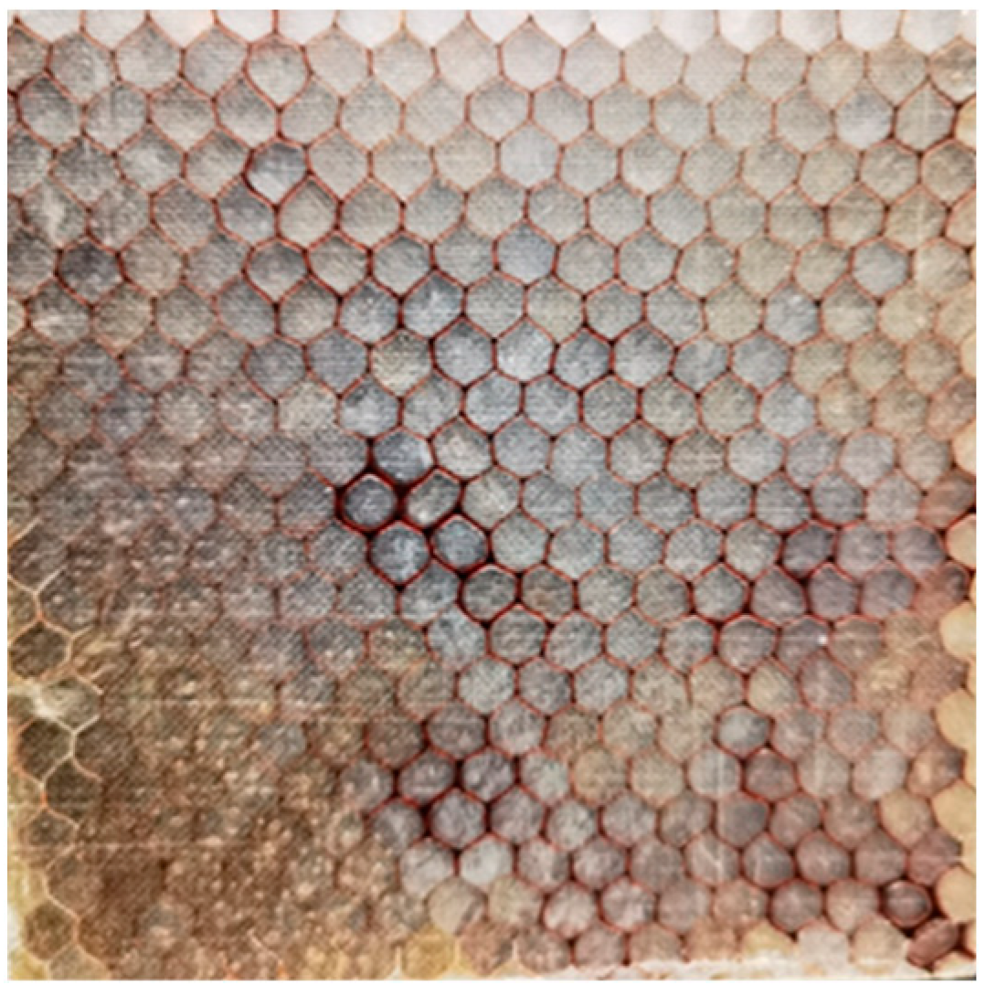
Figure 1 is a UAV skin sample. The UAV skin is a multi-layer transparent composite material. The inner and outer two layers of glass fiber composite material are used as the skin material, and the honeycomb core material is used as the multi-layer structure. On the macro scale, the fabric appears as a collection of interwoven yarn systems. On the meso scale, it appears as a single yarn. The width of each yarn varies from 15 to 25 μm, and every 10 yarns make up a thick thread. The width of the thick thread varies from 0.3 mm to 0.5 mm. The warp and weft yarns are perpendicular to each other and cross-wound, which forms lots of regular knots on the surface.
3.1. The Microscopic Image
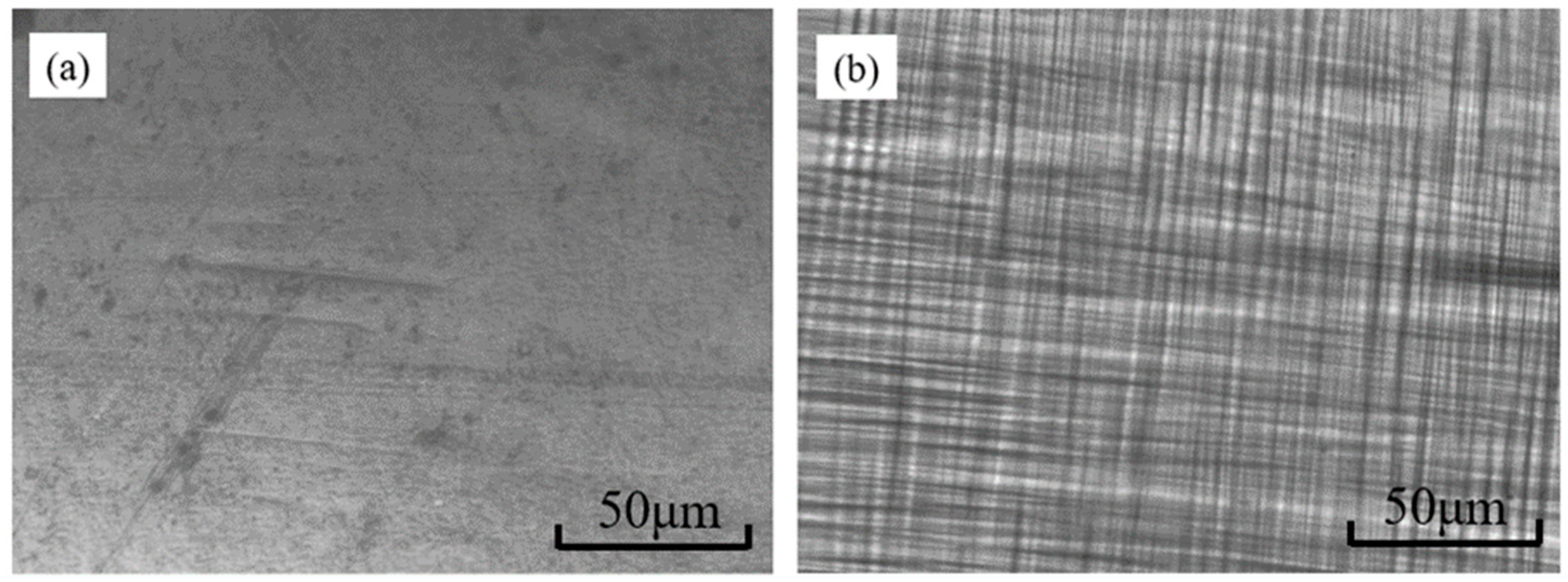
Figure 2 shows the microscopic images of UAV skin.
Figure 2a is the reflection microscope image of the sample. The diffraction limit of the optical system is
, where
is the angular resolution limit of the optical system,
is the wavelength, and
is the aperture diameter of the optical system. The resolution of the system is about 0.4 μm. In
Figure 2, the size of the scale mark is about 50 μm. In
Figure 2a, the surface of the resin material on the skin is rough with almost no air bubbles, peeling, and has degumming and damage defects. In
Figure 2b, it is found that the glass fibers of the skin are distributed horizontally and vertically. The warp and weft yarns cross perpendicularly to each other, creating a tight mesh structure with gaps and knots. In general, these slits have high transmittance and low transmittance at the junctions, so a lattice structure with regular light and dark intervals is formed in the microscopic image. The brightness of different node areas is not uniform, which is caused by the deformation degree of weft and warp at different regions. The deformation information of yarns is unclear due to the scattering and diffraction in the three-dimensional structure of the UAV skin. Although the microscopic image cannot be directly used in the NDT of UAV skin, it can provide supplementary information for Mueller matrix images in this work. The Microscopic images can provide some structural features, such as the distribution and direction of weft and warp yarns.
3.2. The Results of UMMMD
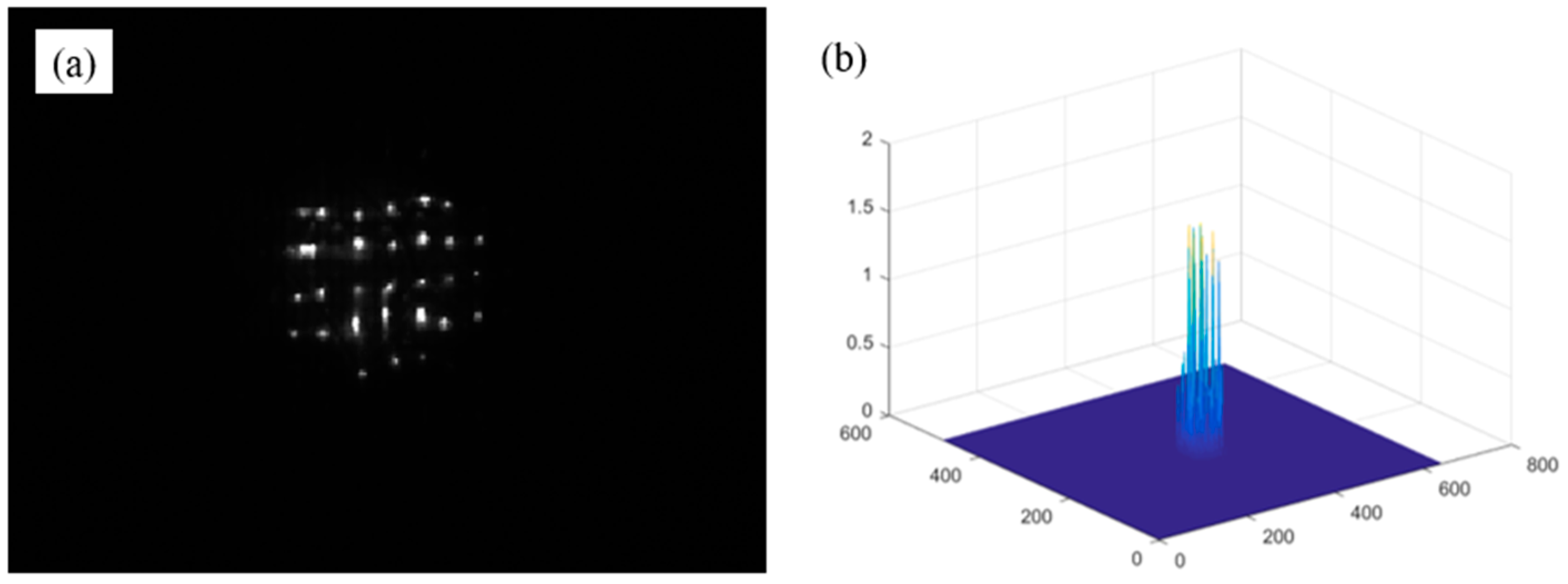
Figure 3 shows the images of intensity of the UAV skin. As shown in
Figure 3a, the average light intensity image is obtained from the 36 coded images. As shown in
Figure 3b, the distribution of the scattering intensity on the skin surface is uneven. A lattice structure image of the skin is obtained. The lattice structure is generated by reflection from a number of yarn nodes. It is found that the incident polarized light is scattered multiple times due to the complex layered structure, including resin materials, the rough surfaces of yarns, honeycomb structures, gaps, bends, etc. Due to the randomness of multiple scattering, the outgoing intensity is weak and difficult to be detected.
The Mueller images need to be normalized since the detected light signal is as weak as the order of 10−5. The Mueller matrix measures the reflection signals from the UAV skin, and the measured Mueller elements are between 10−5 and 10−7 orders of magnitude. It is because the resin surface of the UAVs skin is rough that the internal scattering caused by the 3D structure is serious, and its reflection is weak. The Mueller matrices of all pixels are normalized by dividing their first Mueller matrix elements. Moreover, the eigenvalues for each pixel need to be normalized, since the value of is greater than 1, and its corresponding gray level is greater than 255. To solve this problem, the eigenvalues are divided by the sum of the eigenvalues to ensure that the eigenvalues lie in the range of [0, 1], and the corresponding grayscale values vary from 0 to 255. This operation ensures an accurate mapping of the image grayscale and intensity, which is convenient for the subsequent calculation and image display.
Table 1 is the decomposition results, where the Mueller matrix is obtained with 36 coded images. The measured
reflects the total polarization response from the UAV skin.
and the entropy are calculated with the coherency matrix. In
Table 1, the entropy shows that the multiple scattering is significant and the scattering type is not unique.
Table 2 shows the comparison between UMMMD and some previous methods, where OM represents the optimal method. As shown in
Table 2, the calculation of the Mueller–Jones matrix by the Brosseau method is essentially different from the other four methods. When the measured Mueller matrix is depolarizing,
is the best estimate of the Mueller–Jones matrix. Among these methods, the Brosseau method, PCM, and LRB have the same isotropic depolarization matrix with the form of
.
In the case of isotropic depolarization, only the first element in depolarization matrices carries the information of depolarization. However, when the depolarization is anisotropic caused by non-uniform scattering, these methods cannot provide information for different polarized states. The non-uniform scattering of the UAV skin results in different polarization responses under different polarization states. It is noted that both the Cloude method and UMMMD have anisotropic depolarization matrices. Similar to the Cloude method, the key polarization parameters in UMMMD are simplified. Nevertheless, the depolarization processes of the two methods are essentially different due to different depolarization spaces. In UMMMD, the first element of the depolarization matrix represents the depolarization degree and depolarization coefficients [
14,
24], and the other three elements represent the relative depolarization degree. In the Cloude method, the first element in the depolarization matrix represents the total noise rather than the depolarization degree of the system, and the other three elements represent the magnitude of noises under different polarized states. In general,
of the coherence matrix of the UAV skin are small, but their relative deviations are large. Consequently,
are different from each other, and UMMMD could provide a larger dynamic range of depolarization.
Therefore, UMMMD provides more polarization information related to non-uniform multiple scattering than some conventional methods. In particular, this method can de-scribe differences and changes in depolarization for different polarization states.
3.3. NDT of the UAV Skin
In this section, UMMMD is used for the NDT of UAV skin.
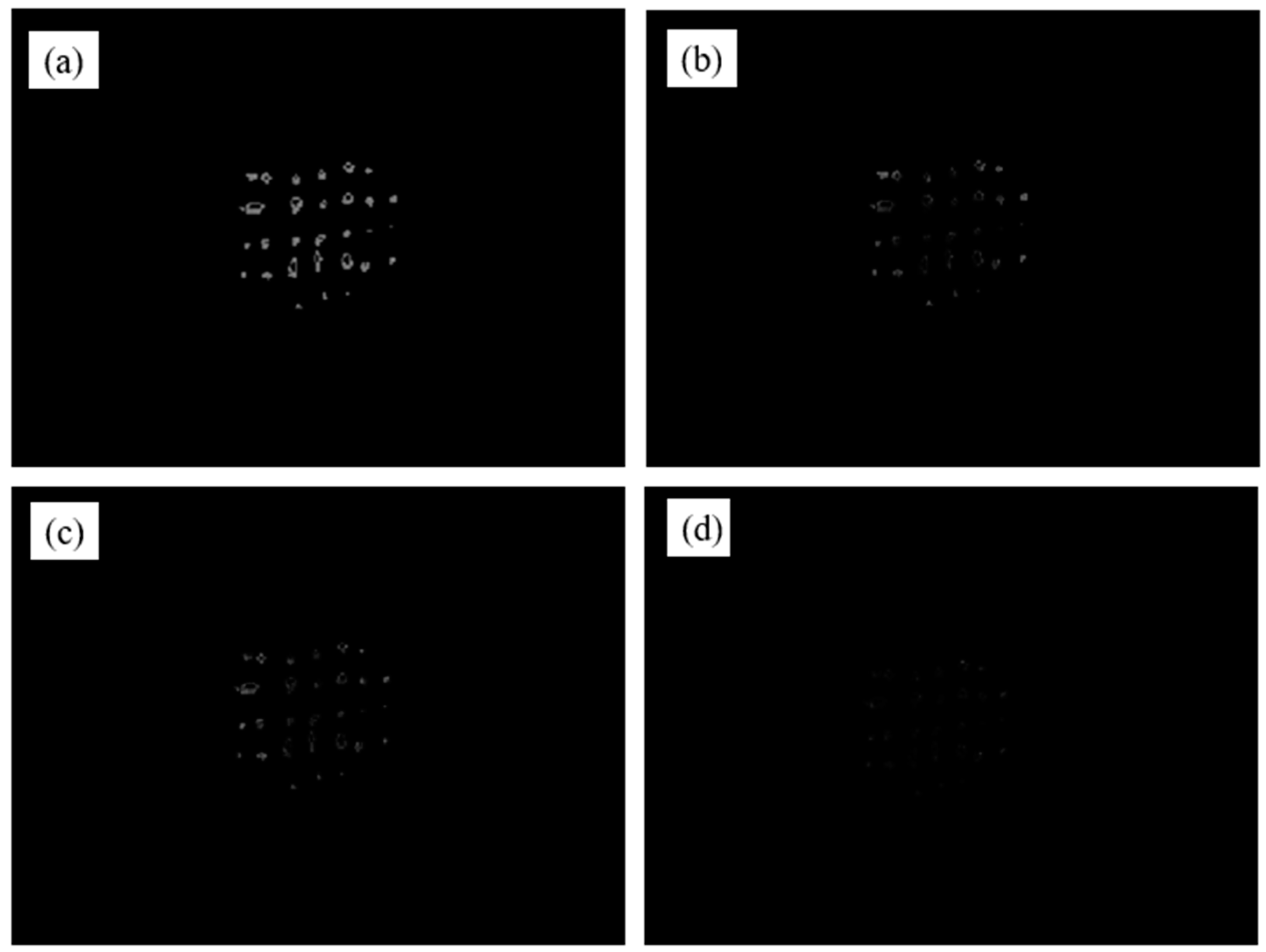
Figure 4 shows eigenvalue images obtained from the corresponding coherency matrices of each pixel.
Figure 4a shows the image
related to the reflection, and
Figure 4b–d reflects the depolarization caused by the scattering of the UAV skin under different polarization states.
Figure 4b–d are blurred since the detected signals under different polarized states are weak. In
Figure 4d, the value of
is close to 0, so the structure information is nearly lost. From
Figure 4, the depolarization under the polarized, elliptical, and circular polarized light is different because of different light–matter interactions. The sharpness of the
images in
Figure 4 is in agreement with the eigenvalues in
Table 1.
In order to characterize the features of the UAV skin, it is necessary to improve the clarity and contrast of the images.
Figure 5 shows the images calculated with the elements in the depolarization matrix. As shown in
Figure 5a, the depolarization at the edge of the sample is larger than that in the center since the scattering at the edge is messier. In
Figure 5b, most of the knots are hollow because the warp and weft yarns at different knots are not evenly stressed during manufacture and use, and then the yarns are distributed to the edge of the node. Accordingly, the edge position becomes tighter than the center position. The different friction force at the knots results in different sizes of the gaps in the knots since the tension distribution of the yarns is non-uniform. The lattice structure is formed by the bright areas reflected by the nodes and the dark areas corresponding to the gaps.
Figure 5c,d are similar to
Figure 5b. However, their contrast is significantly different.
Figure 5d is the image obtained from the absolute value operation of
. The polarization responses of the UAV skin are non-uniform since the properties and structures of different areas are different.
Table 3 shows the contrast of
Figure 3,
Figure 4 and
Figure 5. As shown in
Table 3, the contrast of the original intensity image is very low since the multiple scattered photons decrease the imaging resolution and contrast. The contrast of the
images is low since multiple scattering is serious under different polarization states. Although the values of
are small, their relative errors are large due to the dispersion of the three values. Accordingly, the contrast of the
images is improved, especially the contrast of the
image. In
Table 3, the contrast of the
image is improved by about 13 times than that of the intensity image in
Figure 3.
Table 4 shows the NDT results of the UAV skin in
Figure 5. The shear angle (
) between weft and warp yarns is used as a measure of deformation related to the bending stiffness [
26]. The deformation of yarns in 1, 2, and 3 regions is different. The deformation of region 1 is caused by warp bending, while the deformation of region 2 is mainly caused by the weft yarn. As shown in
Table 4, the change of the shear angle in region 1 is the largest since the warp deformation is the largest, while that in region 3 is the smallest without deformation. When yarns are deformed, their distribution density is greater than that of normal yarns. The density of region 1 is greater than that of region 3. From
Table 4, the average density is about 20/cm
2.
The discussions and results are as follows:
- (I)
Non-uniform multiple scattering is closely related to the complex structure and nature of the UAV skin. Some traditional MMP methods encounter difficulty due to multiple scattering reduces the contrast and clarity of the original images. However, the proposed UMMMD can measure complex depolarization effects and provide more depolarization information for different polarization states.
- (II)
Mueller matrix images for the NDT of the UAV skin sample are in agreement with the Mueller matrix decomposition results. The contrast and sharpness of the images are improved.
- (III)
The method is sensitive to the non-uniform structure of the UAV skin and exhibits large dynamic ranges of depolarization related to multiple scattering.
Therefore, UMMMD is feasible for the NDT of UAVs skin. The given method could be used to characterize key parameters such as the structures, deformation, and defects of UAVs skin. In further research, this method will be used to study the NDT of other composite materials to obtain more extensive applications.
4. Conclusions
In this work, UMMMD is proposed for the NDT of UAVs skin. The method utilizes unitary matrix transformation to generate a depolarized space related to multiple scattering. In this way, the depolarizing Mueller matrix is decomposed into polarized and depolarized parts related to the reflection and the multiple scattering, respectively. The non-uniform depolarization effects can be calculated with the given depolarization matrix and entropy. The method provides more polarization information related to non-uniform scattering than some traditional methods.
Moreover, UMMMD is used for the NDT of UAV skin. By using the method, the contrast of the polarization images has been greatly improved since the noises in the images are effectively suppressed. The Mueller matrix images of the UAV skin are consistent with the Mueller matrix decomposition results. Meanwhile, the provided method exhibits large dynamic ranges, and is sensitive to the non-uniform structure of the UAV skin. The key features of the NDT such as the deformation, shear angles, and density are successfully obtained.
It has demonstrated that the method is feasible and flexible for the NDT of UAVs skin. The proposed method could be beneficial for the NDT of 3D composite materials, intelligent skin design and manufacture, and light–matter interactions of rough materials.


