Article

Efficient Reachable Workspace Division under Concurrent Task for Human-Robot Collaboration Systems

1
Academy of Medical Engineering and Translational Medicine (AMT), Tianjin University, Tianjin 300072, China
2
School of Precision Instrument and Opto-Electronics Engineering, Tianjin University, Tianjin 300072, China
*
Author to whom correspondence should be addressed.
Appl. Sci. 2023, 13(4), 2547; https://doi.org/10.3390/app13042547
Submission received: 18 December 2022 / Revised: 16 January 2023 / Accepted: 7 February 2023 / Published: 16 February 2023

Abstract

:
Division of the reachable workspace of upper limbs under different visual and physical conditions, finding the efficient reachable area under concurrent task conditions, and using it as a basis to divide the incorporation boundaries that require robot assistance are the focus of this paper. These could be used to rationalize the allocation of human and robot workspaces to maximize the efficiency of multitask completion, which has significant applications in the enhancement of human–robot collaboration (HRC) capabilities. However, research on this has rarely been conducted due to the complexity and diversity of arm movements. In this paper, we considered the physical and visual restrictions of the human operator, extracted the movement data of 10 participants while completing the reaching task, and divided the workspace into five areas (their angles are 0°~44.761°, 44.761°~67.578°, 67.578°~81.108°, 81.108°~153.173°, and 153.173°~180°). Measuring the concurrent task completion times when the target object is in each area, respectively, we demonstrated that areas I~II are efficient, reachable workspaces for the human. In the non-efficient reachable workspaces, the average completion times for HRC were 86.7% for human operators (in area III) and 70.1% (in area IV), with the average number of warnings reduced from 2.5 to 0.4. The average completion time for HRC in area V was 59.3% for the human operator, and the average number of warnings was reduced from 3.5 to 0.5. Adding robotic assistance in this area could improve the efficiency of the HRC systems. This study provided a quantitative evaluation of human concurrent task completion capabilities and the incorporation boundaries of robots, which is a useful reference for achieving efficient HRC.

1. Introduction

“Man owes a good part of his intelligence to his hands” [1]. However, upper-limb movement capacity still has deficits in a variety of situations. For example, in engineering maintenance, physical activity is often restricted by the work environment, and hands cannot quickly reach certain work positions, resulting in less efficient completion of tasks and causing fatigue and injury to the operator [2]. This situation is more evident in special fields, such as aerospace and military, wherein special working conditions could make the task more difficult to complete and increase the physical burden. In addition, people often desire to improve their ability to accomplish multiple tasks at the same time [3]. In these situations, to enhance human upper-limb mobility and enlarge the human reachable workspace, it is necessary to collaborate with external devices such as exoskeletons [4], supernumerary robotic limbs [5], and collaborative robots [6,7,8]. Whether these external devices can find the appropriate joining boundaries to achieve physical and cognitive enhancement and accomplish natural cooperation with humans for efficient human–robot collaboration (HRC) systems are an active topic of discussion in the scientific community.
Efficient HRC systems require the rational allocation of human and robot workspaces, with robots assisting at locations where humans have difficulty reaching quickly, reducing the time to complete tasks (without interfering with the tasks being performed by human operators), and improving the ability to complete multiple tasks simultaneously [9,10]. This also corresponds to the definition of HRC: “State in which a purposely designed robot system and an operator work on simultaneous tasks within a collaborative workspace [11]”. It requires first recognizing the motion being performed by the human operator to explore the components that need to be incorporated by the robot. Previous studies made efforts to explore methods of machine learning to enable robots to identify human motion; some researchers implement this work through neural networks [12,13], neuro-fuzzy inference system-based classifiers [14,15]. For instance, the work of [16] integrated a data-driven musculoskeletal model into a robot interaction controller to recognize human movements and classified them according to the model to match the corresponding robot trajectory for application in HRC scenarios. However, these efforts are task-oriented and analyzing each movement they can perform and building datasets is impossible due to the complexity of the arm movements. Thus, for simplifying the process of recognizing upper-limb movement, we aim to find a method that classifies the type of upper-limb movements in the full workspace and find the regularity that exists between them, so that the robot can quickly perceive the position that needs to be added to optimize the efficiency of the task.
Lin et al. [17] introduced five work tasks on a computer assembly line and decomposed them into different parts, such as moving and holding the CPU and main board, putting the rings into the main board, and gluing the fan. They divided the fine manipulation and repetitive motions and allocated them to human operators and robots, respectively, to explore within which segments robots could be added to reduce task accomplishment time and improve task efficiency. Gloumakov et al. [18] analyzed the main characteristics of joint angles during different daily living (ADL) tasks and ultimately found patterns between human upper-limb joint angles under different motions in unstructured environments through data-driven clustering approaches and used them as a basis for robot control [19]. In conclusion, efficient HRC systems require the classification of the human movement behavior and rational allocation of the parts to be completed by the human and the robot. However, these studies have remained with the task-oriented approach to analysis and have not evaluated upper-limb movement capacity within the full workspace in a nonstructural environment. Therefore, we aimed to summarize human movement patterns by a quantitative index of task completion efficiency.
During HRC, regardless of whether the target object is single or multiple, the robot and human focus on the same task, which is called the single task in this paper. For example, in surgery [20], the robot replaces the nurse in handing the surgical instruments to the doctor. In the process of supermarket shelf organization [21], the robot hands the products to the human, and the human operator attaches the corresponding labels and places them in the corresponding positions. In addition, single tasks are common in various scenarios, such as pathological examination [22] and daily life. In these tasks, the human and the robot have different main workspaces. Human operators perform tasks that are mostly focused on areas that can be reached quickly by both hands, such as the front of the vision, which is the workspace efficiently reachable by human bodies, and the robot transfers objects outside this area to the human operator. Thus, in dividing the efficiently reachable workspaces of the human body, finding a suitable boundary for the HRC system, and exploring areas where adding robot assistance could maximize efficiency, it can provide a reference for the robot to understand human behavior and the appropriate distribution of tasks between humans and robots.
The efficiently reachable workspace for humans is highly correlated with its physical condition. When the object being manipulated is located in front of the human chest [23], human reaction speed and motion ability are at a remarkably superior level, and restrictions on body parts could lead to a decrease in upper limb capabilities. For example, in large aircraft assemblies, the interior environment is narrow, and the maintenance workers have difficulty turning their heads and bodies, making it difficult to reach certain positions with their hands. In addition, visual restrictions could also affect the movement status of the upper limbs, such as watching computer screens, reading documents, and assembling mechanical components. Under these situations, eyes are frequently in a state of gazing and central vision is anchored in a specific position. For finishing a concurrent task (getting a document, getting a water cup, or taking up an instrument), peripheral vision is required to provide movement information. The upper-limb movement performance will be greatly impaired compared to natural movement without visual restrictions [24,25,26]. This is also demonstrated in the driving and turning tasks of vehicles [27]. Thus, in humans, having different bodies and visual patterns in different task scenarios will have an impact on the efficient reachable workspace for their upper-limb movements. We aim to divide this workspace definitively and add robotic assistance in the nonefficient reachable workspace to increase the effectiveness of the HRC.
Based on the above, the contribution of this paper is to divide the efficient reachable workspace accurately under the different physical and visual conditions and verify it in a work environment by using task completion time and the number of disturbances in the visual main task as indexes, providing a reference for quantifying the boundaries of robot incorporation in efficient HRC systems. The organization of the whole paper is as follows: Section 2 introduces the preliminary works of the experiment and experimental procedure; Section 3 presents the results of upper-limb workspace division and the comparison of HRC task completion efficiency based on an efficient workspace; and Section 4 discusses the results and applications. Finally, Section 5 summarizes the whole paper.

2. Method

This research is divided into two experimental parts. In the first part, human behavior experiments divide the reachable workspace under different physical and visual modes. In the second part, uniformly selected task target points in each workspace area of the first part, designed concurrent grasping movement experiments with a visual main task to verify the rationality of the workspace division and explored the efficient workspace of the human body, and then added the robot to divide the incorporation boundary of the robot in the human–robot collaboration system.

2.1. Reachable Workspace Division

2.1.1. Participants

The experiment was completed by ten participants (6 males and 4 females, with an average age of 21.4 years). The participants presented with normal or modified-to-normal visual acuity and without any known muscular neurological disorders. Their arm lengths varied from 65.4 to 77.8 cm, ranging to an average length of 71.1 cm, which was measured as the distance between the scaphoid and the radioulnar. All participants were right-handed. Participants gave informed consent, and the study was approved by the Tianjin University Research Ethics Committee.

2.1.2. Experiment Protocol

Part A Gaze State

Gaze states mostly occur in desktop work scenarios, where the object to be gazed at is located in front of the eyes and the pitch angle of the head is small. Therefore, our research divided the reachable area in the gaze state in the 2D space, and then discussed the effect of height on it. Target points in 2D can be selected more densely, thus improving the experimental accuracy while ensuring that the experiment can be implemented. The participant was seated in a height-adjustable chair in front of a table of 75 cm height, with a distance of 15 cm from the participant’s chest. Visual excitement was presented at a flat surface monitor at a distance of 80 cm from the table. The manipulated object was a PVC rectangular block (1.5 × 3 × 1), with the initial placement at the perpendicular midline of the table. It is moved to the sides along the marked lines on the table during the experiment. The participant’s waist was straight, head and trunk oriented to the table, while the center of the shoulder (RSHO) is aligned with the table’s center line.
In the beginning, the participant’s right hand was positioned in Box 1 in Figure 1. After hearing the “Started” prompt, the participant should use the thumb and index finger to elevate the object, then drop it, put it back on the table, and, finally, retract the hand along the initial route to the position of Box 1. The participants needed to keep their eyes fixed on the cross in the center of the screen. At the end of each grasp, the PVC block is moved in a circle, where RSHO is the center, and the length of the arm is an axis. Considering 1 or 2 times grasp error, the moving angle of the object is set to 2°. The participants executed the mission in 3 manners: (1) maintaining the head and staying physically unmoving; (2) maintaining the physically unmoving state while the head could be turned; and (3) both the physical and head could be rotated. The experiment was performed three times, and the height of the chair was adjusted to 48 cm, 55 cm, and 62 cm, respectively. Under the different chair heights, each type was repeated 3 times. The experiments required 85 min to complete.

Part B Non-Gaze State

Compared to the gaze condition, most tasks in daily life occur in the non-gaze condition, and their task scenarios are not limited to desktop tasks. Therefore, this research extended the range of target points to the 3D workspace for experiments in the non-gaze state. However, if the parameter of the moving angle has remained at 2°, the number of reachable points in the 3D workspace is enormous, and it is impossible to complete the grasping of each point in the experiment scene. The choice of the parameter is essential. Setting too large will lead to errors, and setting too small will increase the complexity of the experiment, making it difficult to complete. Therefore, by modeling and clustering the human workspace, we set the moving angle between centroids of each cluster as the distance between adjacent reachable target point positions so that it can be uniformly distributed to represent the entire workspace. The process of target points set in detail is presented in Appendix A.
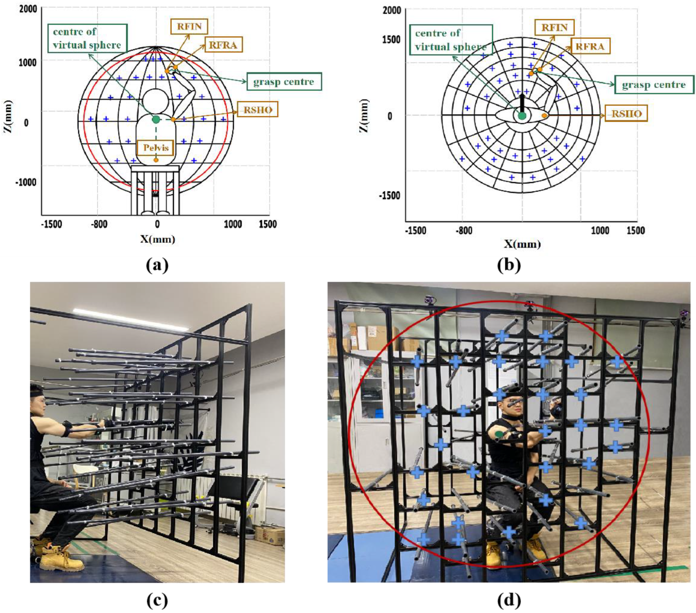
A 3D spherical workspace frame customized for the grasping experiment was installed, and the center of the sphere is indicated by a green dot in Figure 2, aligned with the participant’s RSHO. The target points are indicated by blue crosses, corresponding to the 84 clustering centers calculated by K-means and adjusted according to each participant’s arm’s length. The experiment was performed at the head 60° upward, 30° upward, 0°, −30° downward, and −60° downward, respectively, maintaining a constant head pitch angle in various task types. The participants executed the mission in 3 manners: (1) maintaining the head and staying physically unmoving; (2) maintaining the physically unmoving state while the head could be turned; and (3) both the physical and head could be rotated. Each type was repeated 3 times, and the experiment took approximately 85 min to complete. After hearing the “Started” prompt, participants moved their arms from the starting position to the target point and grasped in turn until they reached the maximum range they can reach.

2.1.3. Data Acquisition

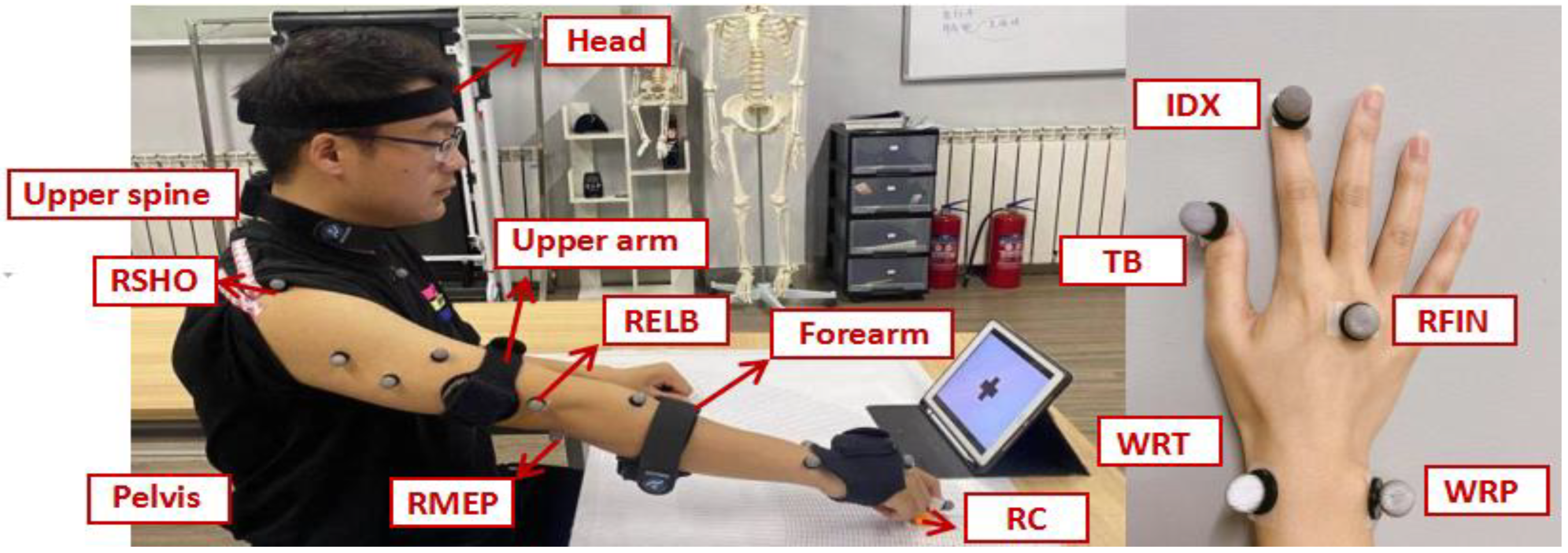
An optical motion capture system, VICON, was used for recording the 3D coordinates data and kinematic data. Five retro-reflex landmarks were placed on the WRT (the styloid process of the radius), the WRP (the styloid process of the ulna), the RFIN (third right finger), the TB (thumbnail), and the IDX (index fingernail) of the hand, and one retro-reflective marker was placed on the RC (object center) [28]. This labeling method was used in our previous work and has proven to be able to obtain upper-limb movement data. Noraxon’s 3D system calculates the 3D rotation angle of each sensor in the IMU. The Noraxon and Vicon devices were connected using a synchronization box. The participants had five IMUs, on the participant’s head, upper spine, right upper arm, forearm, and pelvis (see Figure 3), for establishing upper limb positions and recording head and physical rotation angles. The RSHO positions were normalized for each participant.
A successful grasp is defined as TB, IDX, and the marker of the target point being at the same level and reaching the position at once, and statistical analysis is performed using GraphPad Prism 9.0 (San Diego, CA, USA). Three types of tasks were designated as three regions, and information on the position of the target point at which the subject could complete the first grasp and the last grasp at different task types was extracted. The angle between the two positions is the corresponding reachable area range. Angles of each area and chair height were analyzed by one-way ANOVA (48 cm, 55 cm, and 62 cm) in the gaze state and head pitch angle (−60°, −30°, 0°, 30°, and 60°) in the non-gaze state to observe differences in the division of the workspace at different heights. Statistical significance was set at p < 0.05.

2.2. Efficiently Reachable Workspace and Robot Incorporation Boundary Exploration

2.2.1. Participants

The experiment was completed by ten participants (7 males and 3 females, with an average age of 22.3 years). The participants presented with normal or modified-to-normal visual acuity and without any known muscular neurological disorders. The ethics committee of Tianjin University approved the study, and all participants have individually consented. All participants were right-handed.

2.2.2. Experiment Protocol

Concurrent tasks in this experiment are the visual main task and the upper limb grasping task, which need to be completed simultaneously. The experimental scenario is as follows: The height of the table and chair in the gaze state was maintained constant, and the targeted object was a ball 3 cm in diameter. A spiral base was installed at a distance of 10 cm from the center line and the edge of the table, respectively, and the ball had holes that could be attached to the base. The distance from the edge of the table remained according to the greatest gripping distance of various subjects with no elbow flexion. The visual stimulus was presented in a computer monitor 40 cm in length, and the main stimulus was a ball-avoidance game in which the participant manipulated the ball to avoid obstacles in its path by moving the buttons left and right. The participant was seated in a chair with the waist straight.
The experimental group was asked to start the task by asking the subject to keep the head and body square to the center line of the table, and put the right hand in the initial position, as box 2 shows in Figure 4a. When hearing the sound of the “started” prompt, they were to grasp the target ball, install the ball on the base in front of them, and, finally, return the hand to the initial location. The entire grasping process should ensure that the ball avoidance game continues. At the end of each grasp, the target object’s location is moved on a circle, with the center of rotation of the arm as the axis and the maximum grasp distance as the radius. In this study, according to the clustering results in the 3D workspace, the movement angle of each grasping object was set at 10°, with uniform distribution in each workspace area for different body patterns. The control group added the assistance of the robotic arm, and the experimental environment was kept constant. After the subject heard the prompt, the hand was located at the initial position and kept still, the robotic arm grasped the small ball at the corresponding position and transferred the object to the subject, who installed the small ball on the base.
The two experimental groups were divided into three task phases: reaching and grasping and transferring and installing, respectively. For the experimental group: (1) Subject hears the prompt and moves their hands from the initial location to the location of the target ball. (2) Subject transfers the ball to the base position. (3) Subject installs the ball on the base. For the control group: (1) The robot arm moves from the initial position to the target ball position after the prompt. (2) The ball is transferred to the subject’s hand. (3) The subject installs the small ball onto the base. To ensure the experiment’s reasonability, the handpiece’s initial position was 2 cm to the right of the base to facilitate the installation of the ball. The time required for the subjects to complete the path process of phases 1 and 2 was measured by the experimental group, and the initial location of the robotic arm was set at the same distance between the initial location of the human hand and the small ball, while the movement speed of the robotic arm was adjusted in the control group to make its movement time consistent with the experimental group. The only variable that ensured the experiment was the reaction time of the subjects.

2.2.3. Data Acquisition

An optical motion capture system, VICON, was used to record 3D coordinate data of the target position point and kinematic data. As shown in Figure 4a, five retroreflective markers (10 mm in diameter) were placed on the styloid process of the radius (WRT), the styloid process of the ulna (WRP), the third right finger (RFIN), the thumbnail (TB), and the index fingernail (IDX) of the hand. Hand models were established by each marker, and the end of each phase was considered when the movement speed of the participant’s hand was 0. Warning frequency is the number of ball collision obstacles recorded in the game. Statistical analysis is performed using GraphPad Prism 9.0, recording the time of each phase of the entire process from hearing the prompt sound to subjects completing the task and returning their hands to the initial position, as well as the warning frequency in the visually stimulated for the experimental and control groups, respectively. The difference between the task completion time and the warning frequency on the main task for each phase of the experimental and control groups was calculated using a paired T-Test. The statistical significance was set to p < 0.05.

3. Results

3.1. Workspace Division

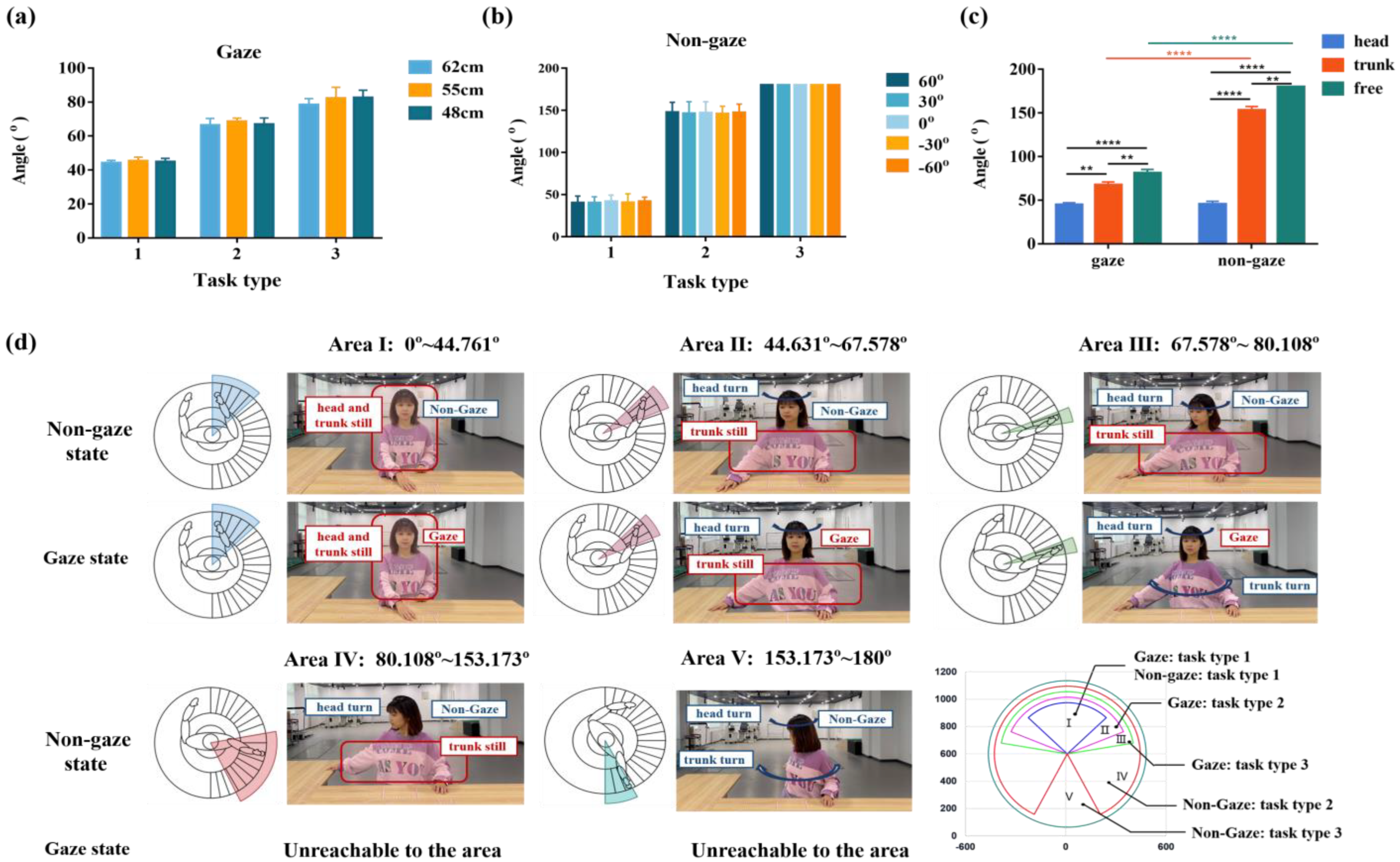
Figure 5a shows the mean ± SD of the angle of each area with different heights under the gaze. When chair height is 62 cm, 55 cm, and 48 cm, the angle of the type (1) is 44.143 ± 2.037°, 45.363 ± 2.763°, and 44.779 ± 2.394°. The angle of type (2) is 66.904 ± 4.005°, 68.466 ± 2.381°, and 67.364 ± 3.835°. The angle of type (3) is 78.453 ± 3.052°, 82.317 ± 4.936°, and 82.554 ± 4.372°. No significant difference was found between the angle and height of each area. (All p > 0.05, p = 0.3997, p = 0.5269, p = 0.4177). Figure 5b shows the mean ± SD of each area angle when the initial angle of the head differs under nongaze. When the initial angle of the head was upward 60°, upward 30°, flat, downward 30°, or downward 60°, the angle of the type (1) is 45.421 ± 3.019°, 45.143 ± 2.898°, 46.587 ± 3.571°, 46.955 ± 3.798°, and 44.049 ± 2.664°. The angle of type (2) is 154.214 ± 4.381°, 153.293 ± 4.451°, 154.903 ± 4.317°, 151.926 ± 3.712°, and 152.159 ± 4.114°. The angle of type (3) is 180°. No significant difference was found between the angle and height of each area. (All p > 0.05, p = 0.4031, p = 0.6047).
Figure 5c shows the mean ± SD of each area angle when the task type differs under the gaze and the non-gaze states. The workspace could be divided into three areas in either case. In the gaze state, the angle of type (1) is 44.761 ± 2.398°, the angle of type (2) is 67.578 ± 3.407°, and the angle of type (3) is 81.108 ± 4.120°. The results show that the effect of task type on the angle is significant (task type 1 and 2: p < 0.01, task type 1 and 2: p < 0.01, and task type 1 and 3: p < 0.001). In the non-gaze state, the angle of type (1) is 45.631 ± 3.190°, the angle of type (2) is 153.173 ± 4.195°, and the angle of type (3) is 180°. The results show that the effect of task type on the angle is significant (task type 1 and 2: p < 0.001, task type 2 and 3: p < 0.01, and task type 1 and 3: p < 0.001). There was no significant difference between the angles corresponding to type (1) in the gaze and non-gaze states (p > 0.5), which divide into area I. There was a significant difference between the angles corresponding to types (2) and (3) (p < 0.001), and the reachable workspace in the non-gaze state is substantially higher than the gaze state, so we defined the extent of task type 2 in the gaze state as area II, and task type 3 as area III. The extent of task types 2 and 3 in the non-gaze state includes areas I~III and the coverage is larger, defined as areas IV and V. The results of the visualization for each area’s extent and body pattern are shown in Figure 5d.

3.2. Completion Time of HRC Tasks

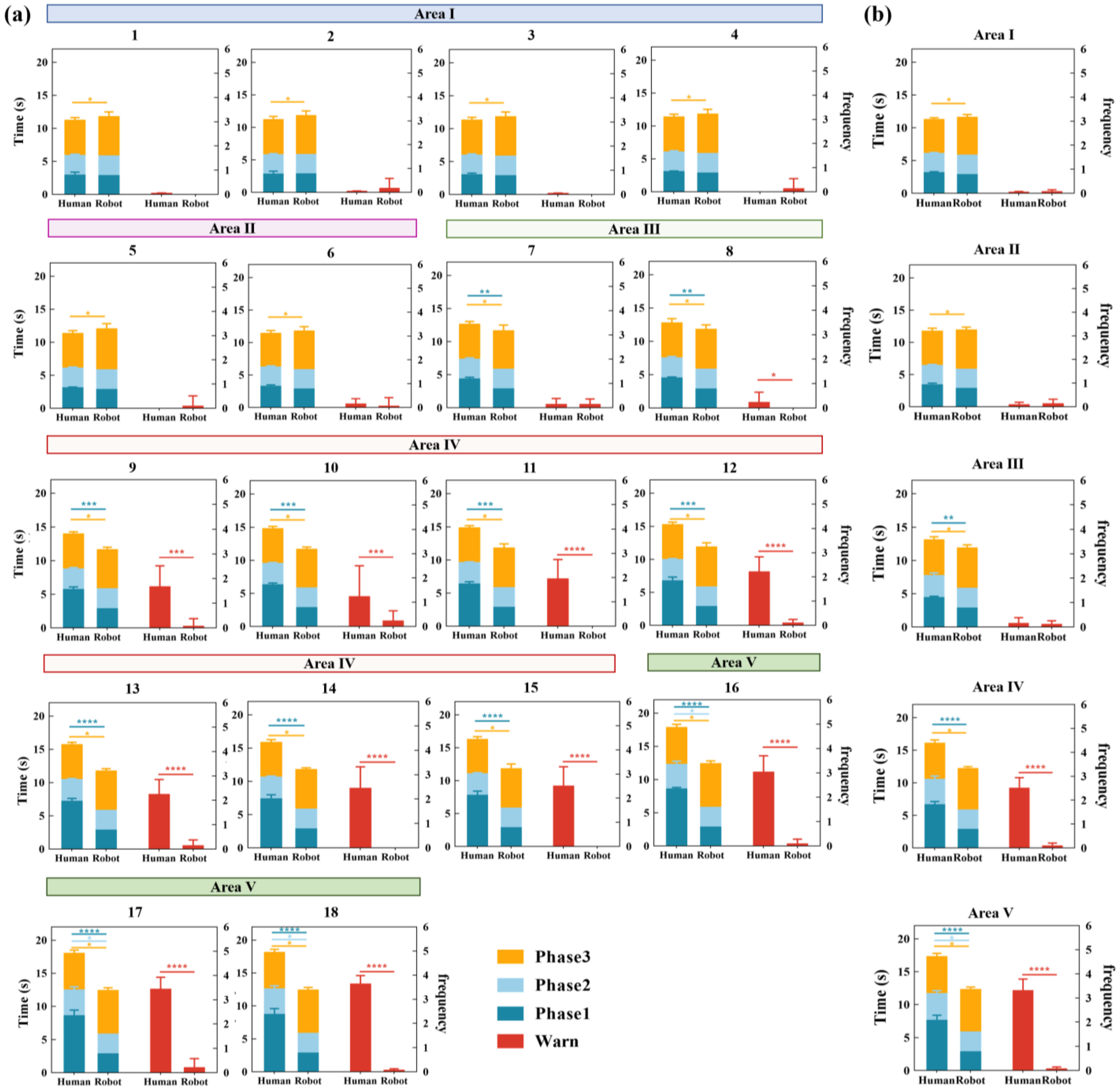
Figure 6a shows the results of the quantitative analysis for the efficiency of the human operator or human and robotic arm collaboration to complete the task. The left Y-axis corresponds to the mean ± SD of task completion time to the human operator or human and robotic arm collaborating when the target ball is located at the first to eighteenth grasping points, respectively. There was a significant difference between the task completion times for each group between human operators and HRC. When the target ball position is located in area I and area II, the difference is small between the task completion time for humans and robots (p < 0.5), and in area III, the difference grows gradually (p < 0.01). In area IV and area V, there is an evident difference in task completion time between the human and robot (p < 0.001). From area I to area V, human operators have significantly increased task completion times, while the robot is essentially constant.
Figure 6. (a) The left Y-axis corresponds to the mean ± SD of task completion time to the human operator or HRC when the target ball is located at the first to eighteenth grasping point, respectively. The left bar chart shows the mean ± SD of task completion time taken by each phase of the human operator. The right Y-axis corresponds to the mean ± SD of warning frequency to the human operator or HRC when the target ball is located at the first to the eighteenth grasping point, respectively. (b) The left Y-axis corresponds to the mean ± SD of task completion time to the human operator or HRC of each area, respectively. The left bar chart shows the mean ± SD of task completion time taken by each phase of the human operator. The right Y-axis corresponds to the mean ± SD of warning frequency to the human operator or HRC of each area, respectively. * denotes p < 0.05, ** denotes p < 0.01, *** denotes p < 0.001, and **** denotes p < 0.0001.
Applsci 13 02547 g006
The left bar chart shows the mean ± SD of task completion time taken by each phase of the human operator. There was a significant difference between the task completion times of phase 3 for each group between human operators and HRC (p < 0.5). Compared to the human operator, the robot has a smaller increase in phase 3. There was no significant difference for phase 2, from area I to area IV, between human operators and HRC (p > 0.5), and in area V, the time required for the human operator has a small increase compared to the robot (p < 0.5). There was no significant difference for phase 1, from area I to area II, between human operators and HRC (p > 0.5), and in area III, the difference in task completion time grows gradually (p < 0.01). In area IV and area V, there is a distinct increase in task completion time for human operators, with a significant difference between humans and robots. (9~12: p < 0.001, 12~18: p < 0.0001).
The right Y-axis corresponds to the mean ± SD of warning frequency to the human operator or human and robotic arm collaborating when the target ball is located at the first to the eighteenth grasping point, respectively. In area I and area II, there was no significant difference between human operators and HRC, and in area III, the difference grows gradually (8: p < 0.5). In area IV and area V, there is an evident difference in warning frequency between the human and robot (9~10: p < 0.001, 11~18: p < 0.0001).
There was no significant difference between the task completion time and warning frequency for each phase within each area. Thus, taking the average value for each area, as shown in Figure 6b, there was a significant difference between the task completion times of phase 3 for each area between human operators and HRC (p < 0.5). The completion time of phase 1 from area I to area II, between human operators and HRC was not significant (p > 0.5) and had a small increase in area III (p < 0.01). There was a significant difference between area IV and area V (p < 0.0001). The warning frequency in area I to area III between human operators and HRC was not significant (p > 0.5), and there was a significant difference between area IV and area V (p < 0.0001).

4. Discussion

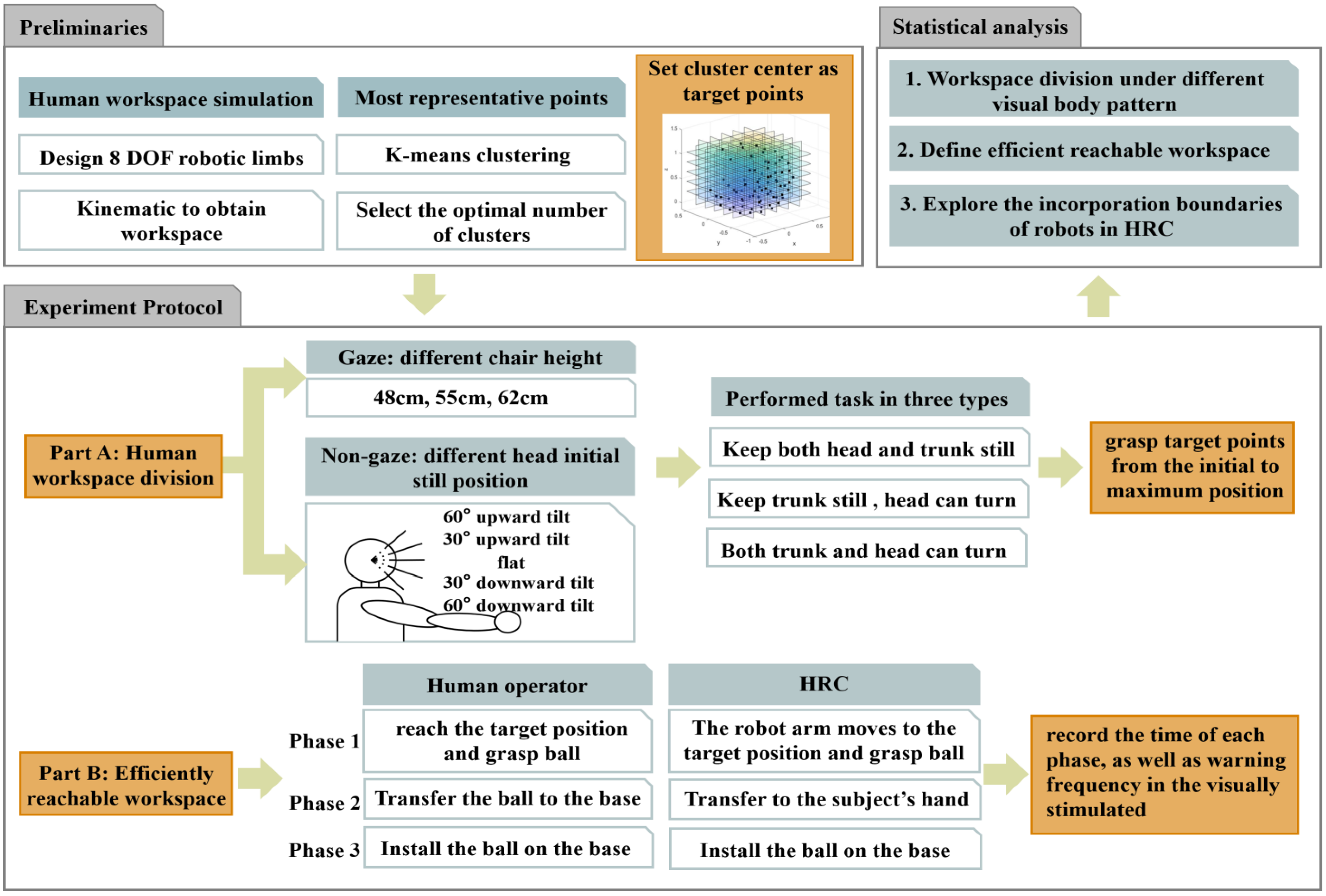
This paper divided the human upper-limb efficient reachable workspace based on different body and visual patterns to provide a basis for the boundaries of robot incorporation in human–robot collaboration systems. The main contributions of this paper are that it (1) summarized the movement patterns of the human body and divide the upper limb workspace into five areas; (2) divided the human body’s efficient reachable workspace and found the most convenient workspace for HRC, and cooperation within this area helps improve the concurrent task completion ability; and (3) verified that adding the assistance of robotic arms in nonefficient reachable areas can significantly improve the efficiency of HRC tasks by using task completion time and concurrent task capability as indexes and precisely dividing the joining boundary of robots in HRC systems. The overall experimental and analysis procedure framework is illustrated in Appendix B. When the tasks are located in different areas, we show the human operation individually and the human-machine collaboration through videos in the Supplementary Materials. Some interesting observations will be discussed in the rest of this section.
Firstly, we divided the upper-limb workspace into five areas since there is no significant difference between the angles of each area under the gaze state when the chair height is changed or when the head pitch angle is changed under non-gaze state, and there is no significant difference between the angles obtained from different participants. Therefore, the results are stable and can be generalized to the analysis of human movement capacity in nonstructural environments. We averaged the obtained angles of each area. Analysis from the right side: area I is 0°~44.761°, participants could reach area I without any physical movement in gaze and non-gaze states; work in this area is extremely easy to accomplish, and neither physical nor visual limitations are sufficient to affect tasks in this area. Area II is 44.761°~67.578°; work tasks in this area require head turns to be completed under the gaze state and non-gaze state. Area III is 67.578°~81.108°; tasks in this area require head and body turns if in the gaze state, or just head turns in the non-gaze state. Area IV is 81.108°~153.173°; in the gaze state, the work task cannot be completed in this area and requires simultaneous head turn with no visual restrictions. Area V is 153.173°~180°; the body needs to be turned without visual restrictions to complete the work task.
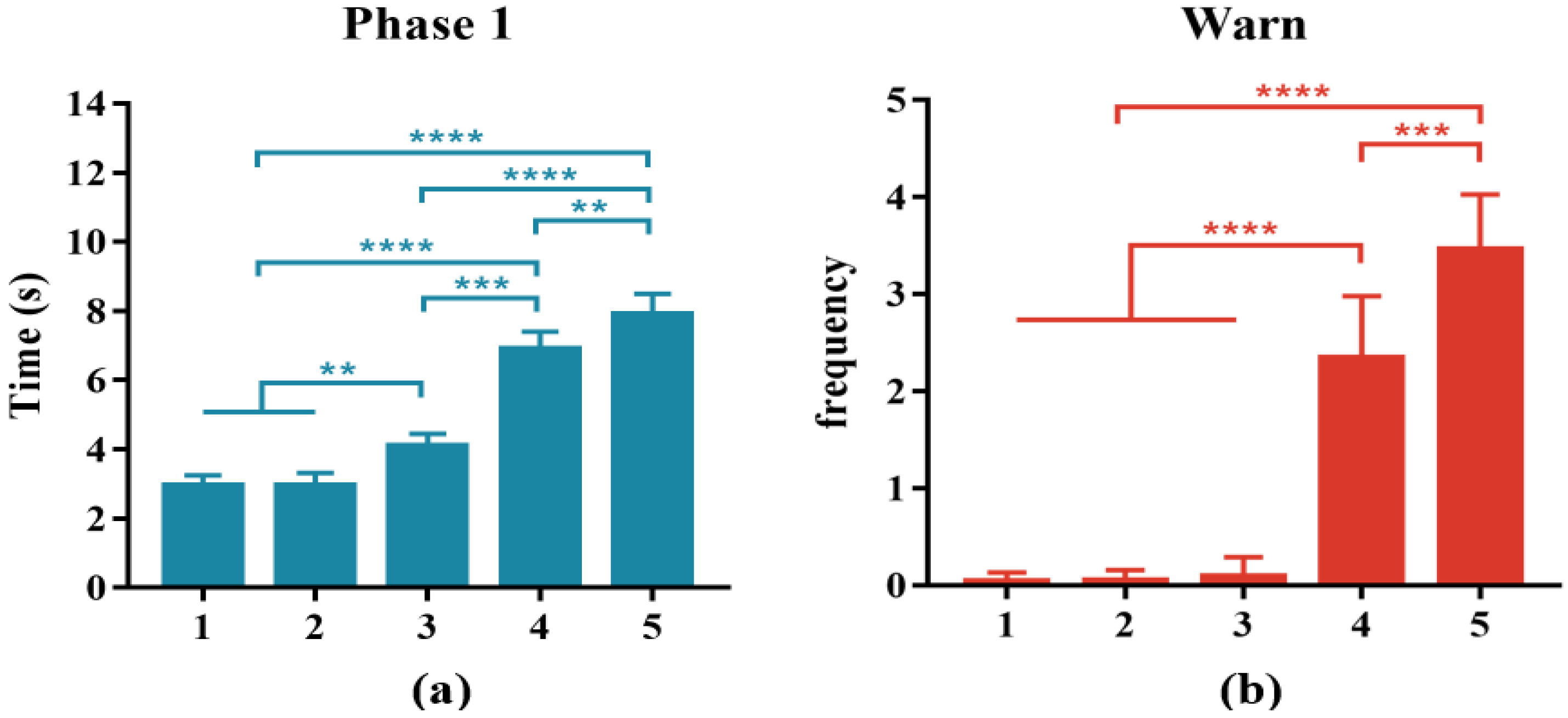
Secondly, we analyzed the task completion time and the warning frequency of the visual main task for each grasp position of the human operator. There is no significant variation in them in each area, demonstrating that changes in the target object position within each area will not have an impact on the task completion time. There were significant differences between areas, demonstrating that the patterns of human movement differed between each area, which confirms the rationality of the workspace division. As shown in Figure 6, from the area I to area V, the completion times of the human operator in phases 2 and 3 remain essentially unchanged, demonstrating that the transfer of the target ball from the grasp position to the base position and the installation is independent of the target position. However, the time of phase 1 and the warning frequency increased gradually, demonstrating that deviation from the target position could lead to slower responses when having a visual stimulus; the task becomes increasingly difficult to complete and requires increased physical DOF. Therefore, we analyzed the mean ± SD of task completion times in phase 1 and warning frequency for human operators in areas I~V, respectively. As shown in Figure 7a, the time for area I is 2.938 ± 0.314, area II is 3.048 ± 0.391, area III is 4.072 ± 0.335, area IV is 6.878 ± 0.523, and area V is 7.892 ± 0.611. There was no significant difference between the times of area I and area II (p > 0.5), and there was a significant difference between the times for additional areas (p < 0.01). The results show that human operators are highly responsive in completing tasks in areas I~II, have relatively shorter grasp times and can complete other tasks concurrently without interfering with the main visual task. Figure 7b shows the mean ± SD of the number of ball collisions with obstacles completed by human operators in areas I~V, respectively. The number of the area I is 0.14 ± 0.114, area II is 0.33 ± 0.171, area III is 0.373 ± 0.153, area IV is 2.475 ± 0.643, and area V is 3.460 ± 0.568. There was no significant difference between the times of area I, area II, and area III (p > 0.5), and there was a significant difference between the number of additional areas (p < 0.001). Due to the restriction of physical ability, the efficiency of completing the task and the ability of concurrent movement were greatly decreased when the position of the target object is located in areas IV and V; the tasks within areas IV and V are completed very slowly and the number of collisions increased significantly. In summary, we define areas I~II as the efficient reachable workspace, and the delicate manipulations that need to be done by human operators should be focused in this area.
Thirdly, we analyzed the incorporation boundary of robots in HRC systems. In areas I and II, whether robotic arm assistance is added has no significant effect on the completion time of phase 1 and phase 2 of the tasks, and, due to the robotic arm needing to transfer the ball to the human operator, it leads to an increase of the task completion time in phase 3. When the target’s position is located in areas III~V, the task completion time increases due to the restrictions of the human operator’s physical and visual conditions, and the grasping task causes significant interference with the visual main task. Adding the assistance of the robotic arm in this area could reduce the task completion time and improve the concurrent task completion ability and efficiency. The average completion time for HRC was 86.7% for human operators in area III and 70.1% in area IV, with the average number of warnings reduced from 2.5 to 0.4. The average completion time for HRC in area V was 59.3% for the human operator, and the average number of warnings was reduced from 3.5 to 0.5. Thus, in the HRC system, to improve the concurrent task completion capability and efficiency, the tasks in the efficient reachable workspace should be completed mainly by the human operator, on which the tasks that require high flexibility and complexity should be concentrated. In the nonefficient reachable workspace, the robotic arm is needed to assist and cooperate with the human operator to complete the task and achieve an efficient HRC system.
There are still many limitations in this paper, just as the classification of each factor level is not detailed enough. However, we chose to systematically study human movement at the macro level. To conduct experiments more efficiently, environmental factors such as the size and shape of objects were not considered. In this study, we chose to focus on the human body’s ability to perform concurrent tasks and, thus, chose to conduct experiments with objects that can be easily grasped with one hand. This conclusion is mainly applicable to healthy people; for older people with decreased vision and people with impaired upper-limb function, their upper-limb efficiently reachable workspace range will be greatly reduced. Further research is needed to clearly divide efficient workspaces for such people with reduced mobility, including robotic assistance in the nonefficient workspace; the results can be used for rehabilitation training, daily living assistance, and other needs. In addition, the aim of this research is to explore the incorporation boundary of robots in HRC systems to improve the efficiency of task completion by division of the human workspace. In order to further improve the efficiency of our proposed robot, the robot needs to be able to recognize and predict the human motion trajectory in real-time and make real-time trajectory planning, so that the robot can recognize the human operator’s activity and reduce the interference generated to it in areas I~II. The robot also needs to make real-time trajectory planning to cooperate with the human operator to complete the tasks in areas III~V. Finally, we can discuss its application in microrobots through the mechanism of human movement, such as in articles [29,30,31]. The results presented in this work are useful in designing microscale bots, which are capable of executing some specific tasks safely in complex physiological environments within human bodies, and we will continue to discuss these in future research.

5. Conclusions

An efficient HRC system requires a reasonable allocation of workspace between humans and robots—robots that assist the human operators in quickly completing tasks at hard-to-reach locations without interfering with their activities and cooperate in completing multiple tasks simultaneously to improve concurrent task capabilities. The area where the human operator performs tasks is concentrated in locations that can be quickly reached by both hands. In order to enable the robot to quickly perceive where it is required to incorporate to optimize task efficiency, in this paper, we first categorized human movement with task completion efficiency as the main goal, through experimental results in gaze and non-gaze states, demonstrating that the workspace of the upper limb can be divided into five areas according to the physical and visual patterns in different situations (their angles are 0°~44.761°, 44.761°~67.578°, 67.578°~81.108°, 81.108°~153.173°, and 153.173°~180°). Then, we verified that the areas I~II are the efficient reachable workspaces by the task completion time and the number of interferences to the main task generated by human operators, individually and with HRC; there is no need to add robot assistance in these areas. Finally, we analyzed areas III~V and demonstrated that the incorporation of robotic arm assistance in these areas could significantly improve task efficiency.
This research divided the upper limb workspace from the perspective of human movement (with each area corresponding to a different movement pattern), found the workspace where human operators can efficiently complete concurrent tasks and demonstrated whether the addition of robot assistance within each area can enhance the completion efficiency of concurrent tasks. The experimental results were used to divide the main activity areas of humans and robots and to explore in which areas the incorporation of robots can enhance task completion efficiency, as well as the incorporation boundary of robots, which provides an effective reference basis for achieving an efficient HRC system. The results could be used in unstructured environments for HRC situations, such as surgery, engineering maintenance, industrial assembly lines, and daily life. Meanwhile, they can also provide a basis for designing dual-arm robots and external limbs to make them more agile and humanized.

Supplementary Materials

The following supporting information can be downloaded at: https://www.mdpi.com/article/10.3390/app13042547/s1, Video S1: HRC1, Video S2: HRC2, Video S3: HRC3.

Author Contributions

Writing—original draft, W.Z.; Writing—review & editing, Q.C.; Project administration, Y.L. and D.M. All authors have read and agreed to the published version of the manuscript.

Funding

This work was supported in part by the National Key Research and Development Program of China (2022YFF1202500, 2022YFF1201205), National Natural Science Foundation of China (62273251, 51905375), and Natural Science Foundation of Tianjin (21JCYBJC00520).

Institutional Review Board Statement

The studies involving human participants were reviewed and approved by the Tianjin University Human Research Ethics Committee (TJUE-2022-187). The patients/participants provided their written informed consent to participate in this study. Written informed consent was obtained from the individual(s) for the publication of any potentially identifiable images or data included in this article.

Informed Consent Statement

Informed consent was obtained from all subjects involved in the study and was approved by the Tianjin University Research Ethics Committee. Written informed consent has been obtained from the subjects to publish this paper.

Data Availability Statement

No new data were created or analyzed in this study. Data sharing is not applicable to this article.

Conflicts of Interest

The authors declare no conflict of interest.

Appendix A

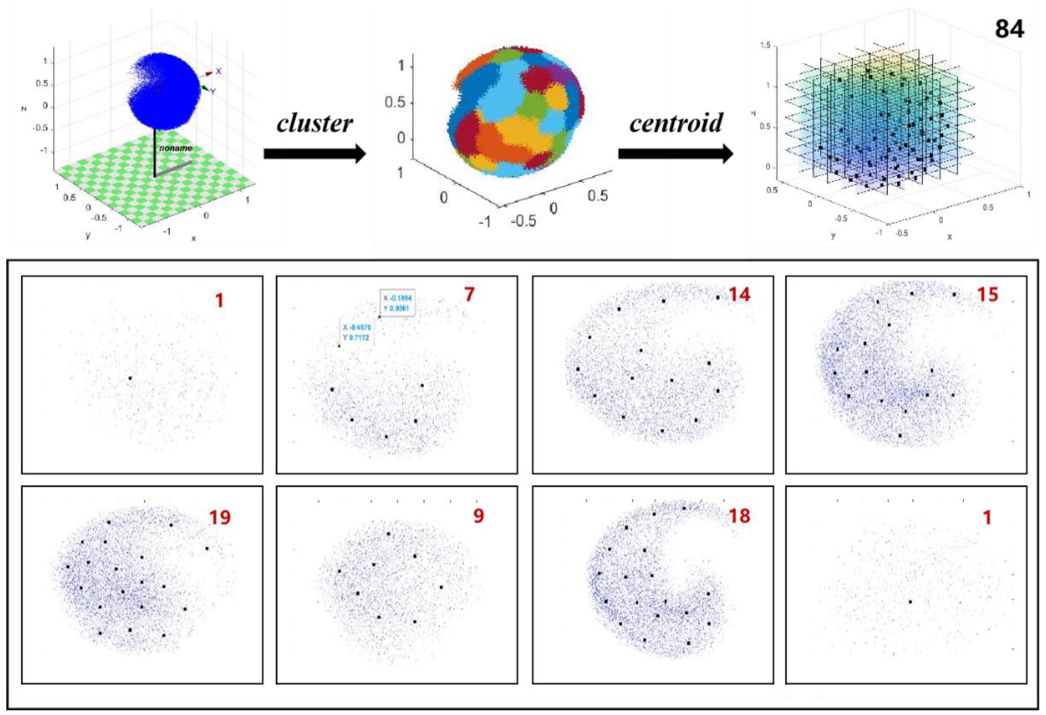
In this research, we simulated the human upper limb workspace, selected 200,000 reachable position points, and performed clustering to select the target position points in the 3D workspace, the detailed procedure is as follows. According to neuroscience research results [32], the robotic limb is anatomically similar to the natural hands. Firstly, we designed a robotic arm with 8 DOF to simulate the human workspace using the robotics toolbox of MATLAB, and the joint configuration is similar to the human natural upper limb [33], we increased 1 DOF on the rotation of the lumbar. The length of the robotic limb is also the same as the simulation human-size according to the international standard ISO-7250-1:2008 [34] and ISO/TR7250-2:2010 [35]. The D-H parameter is shown in Table A1. The end position vector of the robotic arm was obtained by positive kinematics calculation, and the scatter plot of the end position of the workspace was obtained by selecting 200,000 random joint variables using the Monte Carlo method.
Table A1. Standard D-H Parameter.
i a i α i d i θ i
1220−π/2468 θ 1 π / 6 , π / 6
20π/20 θ 2 13 π / 18 , 0
30π/20 θ 3 π / 2 , 3 π / 4
40π/2313 θ 4 π / 6 , 4 π / 9
50π/20 θ 5 π , 2 π / 9
60π/2237 θ 6 π / 2 , π / 2
70π/20 θ 7 π / 6 , 3 π / 4
814800 θ 8 π / 6 , π / 6
Secondly, we clustered the points in the workspace uniformly using the K-mean and found the optimal number of clusters, the position of the points in each region is similar. The cluster center is the most representative point in each region, set as the target point in the experiment. K-means is the most commonly used clustering algorithm. For target points, each point has M dimensions, given the number of clusters as K and the initial cluster center as C 1 , C 2 , C 3 , , C n , 1 K N . The Euclidean distance from each sample point to each cluster center is calculated as:
d i s X i , C j = t = 1 m X i t C j t 2
in which X i represent the i t h point, 1 i N , C j represent the j t h cluster center, 1 j K has t dimensions, assign each point to the cluster represented by the nearest cluster center. After the assignment, the centroids are recalculated based on the points within the clusters. The steps of assigning points and updating cluster centroids are repeated sequentially until the changes are small or the specified number of iterations is reached. After that, we calculate the sum of the squares errors (SSE) and Silhouette Coefficient S for each cluster number.
S S E = i = 1 K p m j p C j 2
S = b a m a x a , b , s 1,1
in which m j represent the j t h cluster and p is the sample point in m j . a represents the average distance between the sample point and all other points in the same cluster, and b represents the average distance between the sample point and all points in the next closest cluster. when S is close to 1, the clustering effect is better. When the number of clusters is over 84, S S E 0.01 and S = 1 . Therefore, the optimal number of clusters in this study is chosen as 84. Cluster procedure and the position of centroids points in the 3D workspace as shown in Figure A1. In the experiment, the positions of these centroids point as target points.
Figure A1. The results of the K-means cluster, the top figure reflects the clustering process for 200,000 points in the workspace, the bottom figure is the profile of the cluster center, and the black points represent the cluster centers, with 84.
Applsci 13 02547 g0a1

Appendix B

In this paper, the overall experimental as well as data analysis procedure is organized and shown in Figure A2.
Figure A2. Overall process framework for experiments and data analysis.
Applsci 13 02547 g0a2

References

  1. Navarro, J.; Hernout, E.; Osiurak, F.; Reynaud, E. On the nature of eye-hand coordination in natural steering behavior. PLoS ONE 2020, 15, 0242818. [Google Scholar] [CrossRef] [PubMed]
  2. Bright, L. Supernumerary Robotic Limbs for Human Augmentation in Overhead Assembly Tasks. Ph.D. Thesis, Massachusetts Institute of Technology, Cambridge, MA, USA, 2017. [Google Scholar]
  3. Penaloza, C.I.; Nishio, S. BMI control of a third arm for multitasking. Sci. Robot. 2018, 3, eaat1228. [Google Scholar] [CrossRef] [PubMed] [Green Version]
  4. Di Pino, G.; Maravita, A.; Zollo, L.; Guglielmelli, E.; Di Lazzaro, V. Augmentation-related brain plasticity. Front. Syst. Neurosci. 2014, 8, 109. [Google Scholar] [CrossRef] [PubMed] [Green Version]
  5. Pratt, J.E.; Krupp, B.T.; Morse, C.J.; Collins, S.H. The RoboKnee: An exoskeleton for enhancing strength and endurance during walking. In Proceedings of the IEEE International Conference on Robotics & Automation, New Orleans, LA, USA, 26 April–1 May 2004. [Google Scholar]
  6. Gierke, H.E.; Keidel, W.D.; Oestreicher, H.L. Principles and Practice of Bionics; Technivision Services: Slough, UK, 1970. [Google Scholar]
  7. Gualtieri, L.; Rauch, E.; Vidoni, R. Emerging research fields in safety and ergonomics in industrial collaborative robotics: A systematic literature review. Robot. Comput.-Integr. Manuf. 2021, 67, 101998. [Google Scholar] [CrossRef]
  8. Liu, Z.; Jiang, L.; Yang, B. Task-Oriented Real-Time Optimization Method of Dynamic Force Distribution for Multi-Fingered Grasping. Int. J. Hum. Robot. 2022, 19, 2250013. [Google Scholar] [CrossRef]
  9. Ajoudani, A.; Zanchettin, A.M.; Ivaldi, S.; Albu-Schäffer, A.; Kosuge, K.; Khatib, O. Progress and prospects of the Human-Robot Collaboration. Auton. Robot. 2017, 42, 957–975. [Google Scholar] [CrossRef] [Green Version]
  10. Kieliba, P.; Clode, D.; Maimon-Mor, R.O.; Makin, T.R. Robotic hand augmentation drives changes in neural body representation. Sci. Robot. 2021, 6, eabd7935. [Google Scholar] [CrossRef]
  11. Wang, L.; Gao, R.; Váncza, J.; Krüger, J.; Wang, X.; Makris, S.; Chryssolouris, G. Symbiotic human-robot collaborative assembly. CIRP Ann. 2019, 68, 701–726. [Google Scholar] [CrossRef] [Green Version]
  12. Burns, A.; Adeli, H.; Buford, J.A. Upper Limb Movement Classification Via Electromyographic Signals and an Enhanced Probabilistic Network. J. Med. Syst. 2020, 44, 176. [Google Scholar] [CrossRef]
  13. Pang, Z.; Wang, T.; Liu, S.; Wang, Z.; Gong, L. Kinematics Analysis of 7-DOF Upper Limb Rehabilitation Robot Based on BP Neural Network. In Proceedings of the IEEE 9th Data Driven Control and Learning Systems Conference (DDCLS), Liuzhou, China, 20–22 November 2020. [Google Scholar]
  14. Kiguchi, K.; Hayashi, Y. An EMG-Based Control for an Upper-Limb Power-Assist Exoskeleton Robot. IEEE Trans. Syst. Man Cybern. Part B 2012, 42, 1064–1071. [Google Scholar] [CrossRef]
  15. Bendre, N.; Ebadi, N.; Prevost, J.J.; Najafirad, P. Human Action Performance using Deep Neuro-Fuzzy Recurrent Attention Model. IEEE Access 2020, 8, 57749–57761. [Google Scholar] [CrossRef]
  16. Bestick, A.M.; Burden, S.A.; Willits, G.; Naikal, N.; Sastry, S.S.; Bajcsy, R. Personalized kinematics for human-robot collaborative manipulation. In Proceedings of the 2015 IEEE/RSJ International Conference on Intelligent Robots and Systems (IROS), Hamburg, Germany, 28 September–2 October 2015. [Google Scholar]
  17. Lin, C.J.; Lukodono, R.P. Sustainable human–robot collaboration based on human intention classification. Sustainability 2021, 13, 5990. [Google Scholar] [CrossRef]
  18. Gloumakov, Y.; Spiers, A.J.; Dollar, A.M. Dimensionality Reduction and Motion Clustering during Activities of Daily Living: 3, 4, and 7 Degree-of-Freedom Arm Movements. IEEE Trans. Neural Syst. Rehabil. Eng. 2020, 28, 2826–2836. [Google Scholar] [CrossRef] [PubMed]
  19. Gloumakov, Y.; Spiers, A.J.; Dollar, A.M. Dimensionality Reduction and Motion Clustering During Activities of Daily Living: Decoupling Hand Location and Orientation. IEEE Trans. Neural Syst. Rehabil. Eng. 2020, 28, 2955–2965. [Google Scholar] [CrossRef] [PubMed]
  20. Zhou, T.; Wachs, J.P. Early Prediction for Physical Human Robot Collaboration in the Operating Room. Auton. Robot. 2018, 42, 977–995. [Google Scholar] [CrossRef] [Green Version]
  21. Costanzo, M.; Maria, G.D.; Natale, C. Handover Control for Human-Robot and Robot-Robot Collaboration. Front. Robot. AI 2021, 8, 672995. [Google Scholar] [CrossRef] [PubMed]
  22. Li, Q.; Zhang, Z.; You, Y.; Mu, Y.; Feng, C. Data Driven Models for Human Motion Prediction in Human-Robot Collaboration. IEEE Access 2020, 8, 227690–227702. [Google Scholar] [CrossRef]
  23. Nakabayashi, K.; Iwasaki, Y.; Iwata, H. Development of Evaluation Indexes for Human-Centered Design of a Wearable Robot Arm. In Proceedings of the 5th International Conference on Human-Agent Interaction, Bielefeld, Germany, 17–20 October 2017; pp. 305–310. [Google Scholar]
  24. Gene-Sampedro, A.; Alonso, F.; Sánchez-Ramos, C.; Useche, S.A. Comparing oculomotor efficiency and visual attention between drivers and non-drivers through the Adult Developmental Eye Movement (ADEM) test: A visual-verbal test. PLoS ONE 2021, 16, 0246606. [Google Scholar] [CrossRef]
  25. Roux-Sibilon, A.; Trouilloud, A.; Kauffmann, L.; Guyader, N.; Mermillod, M.; Peyrin, C. Influence of peripheral vision on object categorization in central vision. J. Vis. 2019, 19, 7. [Google Scholar] [CrossRef] [Green Version]
  26. Vater, C.; Williams, A.M.; Hossner, E.J. What do we see out of the corner of our eye? The role of visual pivots and gaze anchors in sport. Int. Rev. Sport Exerc. Psychol. 2019, 13, 81–103. [Google Scholar] [CrossRef]
  27. Wolfe, B.; Dobres, J.; Rosenholtz, R.; Reimer, B. More than the Useful Field: Considering peripheral vision in driving. Appl. Ergon. 2017, 65, 316–325. [Google Scholar] [CrossRef] [PubMed]
  28. Liu, Y.; Zhang, W.; Zeng, B.; Zhang, K.; Cheng, Q.; Ming, D. The Analysis of Concurrent-Task Operation Ability: Peripheral-Visual-Guided Grasp Performance Under the Gaze. In Intelligent Robotics and Applications, Proceedings of the 14th International Conference, ICIRA 2021, Yantai, China, 22–25 October 2021; Springer: Cham, Switzerland, 2021; pp. 500–509. [Google Scholar]
  29. Asghar, Z.; Ali, N.; Javid, K.; Waqas, M.; Dogonchi, A.S.; Khan, W.A. Bio-inspired propulsion of micro-swimmers within a passive cervix filled with couple stress mucus. Comput. Methods Programs Biomed. 2020, 189, 105313. [Google Scholar] [CrossRef] [PubMed]
  30. Javid, K.; Ali, N.; Asghar, Z. Rheological and magnetic effects on a fluid flow in a curved channel with different peristaltic wave profiles. J. Braz. Soc. Mech. Sci. Eng. 2019, 41, 483. [Google Scholar] [CrossRef]
  31. Asghar, Z.; Javid, K.; Waqas, M.; Ghaffari, A.; Khan, W.A. Cilia-driven fluid flow in a curved channel: Effects of complex wave and porous medium. Fluid Dyn. Res. 2020, 52, 015514. [Google Scholar] [CrossRef]
  32. Tsakiris, M.; Carpenter, L.; James, D.; Fotopoulou, A. Hands only illusion: Multisensory integration elicits a sense of ownership for body parts but not for non-corporeal objects. Exp. Brain Res. 2010, 204, 343–352. [Google Scholar] [CrossRef]
  33. Wu, G.; van der Helm, F.C.; Veeger, H.E.; Makhsous, M.; Van Roy, P.; Anglin, C.; Nagels, J.; Karduna, A.R.; McQuade, K.; Wang, X.; et al. ISB recommendation on definitions of joint coordinate systems of various joints for the reporting of human joint motion—Part II: Shoulder, elbow, wrist, and hand. J. Biomech. 2005, 38, 981–992. [Google Scholar] [CrossRef]
  34. Liu, X.; Zhong, X. An improved anthropometry-based customization method of individual head-related transfer functions. In Proceedings of the 2016 IEEE International Conference on Acoustics, Speech, and Signal Processing (ICASSP), Shanghai, China, 20–25 March 2016. [Google Scholar]
  35. ISO 7250:1996; Basic Human Body Measurements for Technological Design. ISO: Geneva, Switzerland, 1996.
Figure 1. Table layout of the experiment, indicating the hand and object’s initial position.
Applsci 13 02547 g001
Figure 2. (a,b) the spherical workspace in the top and forward views, respectively. (c,d) The participant is reaching; the person permitted the use of this image.
Applsci 13 02547 g002
Figure 3. Illustration of marker and IMUs placement. The person permitted the use of this image.
Applsci 13 02547 g003
Figure 4. The experimental setup is shown in (a). The human operator accomplishes the grasping task concurrently while completing the visual main task on the computer screen. The visual main task for the ball collision game is shown in (b). An outline for every experimental session of the experiment is shown in (c). (d) Photographs of the experimental setup demonstrated the experimental process after incorporating the robotic arm assistance. The person permitted the use of this image.
Applsci 13 02547 g004
Figure 5. Task type 1 is keeping the head still, task type 2 is keeping the head and trunk still, and task type 3 is unlimited. (a) Mean ± SD of each area angle when height differs under the gaze state. There was no significant (p > 0.05). (b) Mean ± SD of each area angle when the initial angle of the head differs under the non-gaze state. There was no significant (p > 0.05). (c) Mean ± SD of each area angle when task type differs under the gaze and non-gaze state. ** denotes p < 0.01, and **** denotes p < 0.0001. The results of the visualization for each area’s extent and body pattern are shown in Figure 6 (d).
Applsci 13 02547 g005
Figure 7. (a) Mean ± SD of task completion times for human operators in phase 1 in areas I~V. (b) Mean ± SD of warning frequency for human operators in areas I~V. ** denotes p < 0.01, *** denotes p < 0.001, and **** denotes p < 0.0001.
Applsci 13 02547 g007
Disclaimer/Publisher’s Note: The statements, opinions and data contained in all publications are solely those of the individual author(s) and contributor(s) and not of MDPI and/or the editor(s). MDPI and/or the editor(s) disclaim responsibility for any injury to people or property resulting from any ideas, methods, instructions or products referred to in the content.