Article

Extraordinary Field Emission of Diamond Film Developed on a Graphite Substrate by Microwave Plasma Jet Chemical Vapor Deposition

1
Department of Mechanical Engineering, National Taipei University of Technology, Taipei 10608, Taiwan
2
Department of Electronic Engineering, National Taipei University of Technology, Taipei 10608, Taiwan
3
Multidisciplinary Computational Laboratory, Department of Electrical and Biomedical Engineering, Hanyang University, Seoul 04763, Republic of Korea
4
Department of Mechanical Engineering, Minghsin University of Science and Technology, Hsinchu 30400, Taiwan
*
Author to whom correspondence should be addressed.
Appl. Sci. 2023, 13(4), 2531; https://doi.org/10.3390/app13042531
Submission received: 5 January 2023 / Revised: 7 February 2023 / Accepted: 11 February 2023 / Published: 16 February 2023

Abstract

:
This work reports both numerical and experimental studies of the reconditioning of a microwave plasma jet chemical vapor deposition (MPJCVD) system for the growth of diamond film. A three-dimensional plasma fluid model is constructed for investigating and conditioning the MPJCVD system and optimizing its operating conditions. The methodology solves electromagnetic wave and plasma dynamics self-consistently using an adaptive finite element method as implemented in COMSOL Multiphysics. The whole system has been modeled under varying parameters, including the reactor geometry, microwave power, and working gas pressure. Using an operating condition identical to the optimized simulation results, the MPJCVD system successfully fabricates a diamond-thin film on a graphite substrate. The SEM image reveals the presence of a diamond film uniformly distributed with particles of a size of ~1 μm. The field emission from the diamond film grown from our homemade MPJCVD system on the graphite substrate presents extraordinary properties, i.e., extremely high current density and relatively low turn-on voltage. The turn-on electric field observed could be as low as ~4 V/μm. This developed model provides valuable physical insights into the MPJCVD system, which guided performance improvements. The work may find applications in surface hardening and provide a better cold cathode for field electron emission.

1. Introduction

In the past decades, carbon nanostructures such as carbon nanotubes and diamond films have attracted a lot of attention due to their extraordinary mechanical, thermal, and electric properties [1,2,3,4,5,6,7]. Diamond films can be characterized by their remarkable field emission properties, wide energy gap, low heat conductivity, great optical penetration, high hardness, and chemical inertness. In addition, it comes with high biocompatibility, which can be used in medical applications. In recent years, micro- and nano-scale diamond films have been used in different industrial, engineering, and medical applications due to their distinctive physical and chemical properties [4,5,6,7]. However, numerous limitations still exist in practical applications. Various factors such as film growth rate, surface roughness, area uniformity, adhesion, stress, operating pressure, and temperature must be further investigated to fully explore the potential of diamond films. There are several ways to fabricate a diamond film, including microwave plasma enhanced chemical vapor deposition (MPECVD), hot filament chemical vapor deposition, and microwave plasma jet chemical vapor deposition (MPJCVD) [8,9,10,11,12,13,14,15,16,17,18,19,20,21,22,23,24,25,26,27,28,29,30]. Compared to vacuum-based plasma processing, microwave plasma processing at atmospheric pressure does have some good advantages. First, the equipment cost is comparatively low, and it eliminates the limitations associated with vacuum compatibility. Second, the low-temperature and high-pressure plasma processes greatly enhance the formation of active chemical species, for example, through high chemical selectivity and low ion densities. In addition, the damage to the film surface is also relatively low, while the adhesion between material interfaces is extremely good. For these reasons, it is very attractive to employ microwave plasma to fabricate diamond films. For the past few decades, diamond film coating has been widely used in industries in cutting tools as surface protective films due to its excellent mechanical properties. The traditional vacuum cathodic arc deposition method had low deposition rates of several tens of nm min−1. Using an MPJCVD and applying a high substrate bias voltage, the deposition rate was increased to several thousand nm min−1 [27]. Hence, MPJCVD has been proven to substantially enhance the deposition rate of diamond films. Furthermore, by applying a multistage magnetic field during deposition to the MPJCVD, a uniform thickness polycrystalline diamond film with a large diameter of up to 4 to 7 inches could be produced [28], demonstrating that the improvement of the deposition temperature and thickness uniformity of an MPJCVD for large-scale diamond film can be achieved with some tailored designs or modifications. Here, the MPJCVD fabrication method was chosen to fabricate the diamond films on a variety of substrates as it might serve as a better surface treatment.
Plasma is a group of charged gas molecules in which the total numbers of positive charges (mostly positive ions) and negative charges (mostly electrons) are approximately equal. Thus, plasma in general is considered electrically neutral. In addition to the two charged particles, there are often a number of excited neutral gas molecules. Therefore, a normal plasma reactor contains neutral gas molecules, ions, electrons, and maneuverable neutral gas molecules. There are different ways to generate plasma, such as by applying a strong electric field to the gas or bombarding it with an electron beam or laser, which can excite the gas into a plasma state [8]. Plasma technology has become prominent in the technological advances of various industries. In semiconductor processes, film growth and etching for different materials are generally treated by plasma. Similarly, plasma technology is used to clean or alter the surface properties of materials to achieve special functions and effects in the semiconductor packaging and textile industries. In the case of diamond film deposition, the carbon atoms required for diamond growth are produced in the plasma of a specific gas mixture. Once a graphite bond forms on the surface, the hydrogen atoms generated in the plasma can bond to the carbon atoms of the graphite bond to react with the etching process. With a high-purity coating, good electrical coupling, and high energy concentration, microwave plasma is widely used in the deposition of diamond films. In general, plasma is a complex system involving nonlinear particle dynamics, physical interactions, and chemical reactions on multiple-spatial and time scales. Experimenting with an MPJCVD for diamond film fabrication by trial and error is not only time-consuming but also costly. With the advancement of modern computers, plasma modeling has become a valuable and necessary tool for understanding plasma physics and has contributed to the research and development of a variety of plasma reactors and their performance improvement and conditioning [31,32,33,34,35,36,37,38,39,40,41]. Shivkumar et al. [32] developed a 2D axisymmetric model of the MPECVD system using the multiphysics solver COMSOL, a finite element method (FEM) based solver that combines the Maxwell solver and the heat transfer solver. The numerical simulation was employed to study the effect of parameters such as reactor geometry, microwave power, and gas pressure. The results showed that the gas temperature is weakly dependent on power but strongly dependent on gas pressure. Wang et al. [39] also proposed a numerical simulation using COMSOL to model the electric field and plasma-density distributions in the MPECVD. A 2.45 GHz microwave plasma reactor with TM021 mode was then physically built, which is based on their simulation result. Uniform single-crystal diamond films can be successfully grown on the substrate. Salgado-Meza et al. [40] showed how total pressure and microwave power affect the electrical conductivity of nitrogen atoms’ grain boundaries when incorporated into ultrananocrystalline diamond (UNCD) films grown by MPECVD. The result showed that the film thickness decreased as a function of growth pressure. It was also found that the electrical conductivity of UNCD films increases once the microwave power and total plasma pressure increase in the film growth process. The maximum electrical conductivity for the UNCD film grown was found at a total pressure of 100 mbar and 4.5 kW microwave power. Wang et al. [41] constructed a two-dimensional axisymmetric numerical model using COMSOL to investigate the effect of positive bias and deposition pressure on the properties of plasma flow inside the deposition chamber during the bias-enhanced MPECVD process. It was shown that as the deposition pressure increases, the temperature of the electrons in the deposition chamber increases as well, locally. The maximum value of the pressure was found to be approximately 30 Torr. Different studies have shown that the effects of pressure and power are crucial for film growth, and plasma modeling plays an important role in supporting experimental processes.
In this work, we report the successful reconditioning of our homemade MPJCVD system for developing diamond films using three-dimensional plasma fluid modeling. The whole system has been modeled under varying parameters, including the reactor geometry, microwave power, and working gas pressure, in order to optimize its operating conditions. Using an operating condition identical to the optimized simulation results, the MPJCVD system successfully fabricates a diamond-thin film on a graphite substrate. We introduce the system configuration and its reconditioning in Section 2, present the detailed formulation and numerical modeling in Section 3, the simulation results and optimization in Section 4, and the experimental results in Section 5. Finally, the conclusion is given in Section 6.

2. The MPJCVD System and Its Reconditioning

The experimental setup of our homemade MPJCVD system for fabricating diamond films is shown in Figure 1, and the corresponding schematic design is shown in Figure 2. The equipment had been developed for several years, but the fabrication of diamond films was not successful. Sometimes a diamond film could be fabricated; however, with the same conditions, the experimental results could not be reproduced. In other words, the MPJCVD system is not reliable, and its configuration has to be reconditioned.
Compared with the MPECVD system, MPJCVD can efficiently generate a uniform distribution of plasma [7]. The MPJCVD system can stably generate a firm and uniform plasma with relatively low energy consumption to fabricate smooth diamond films. At the tip of the antenna, localized plasma can be obtained. The conical structure of the antenna is essential for localizing the input microwave energy to enhance the electric field in a certain region and stabilize the energy distribution in plasma. The activity of reaction species and dissociation rate can be greatly increased through the microwave-coupled plasma jet. Compared with the CVD process, MPJCVD reduces the required power for the operating pressure using CH4 and H2 gases.
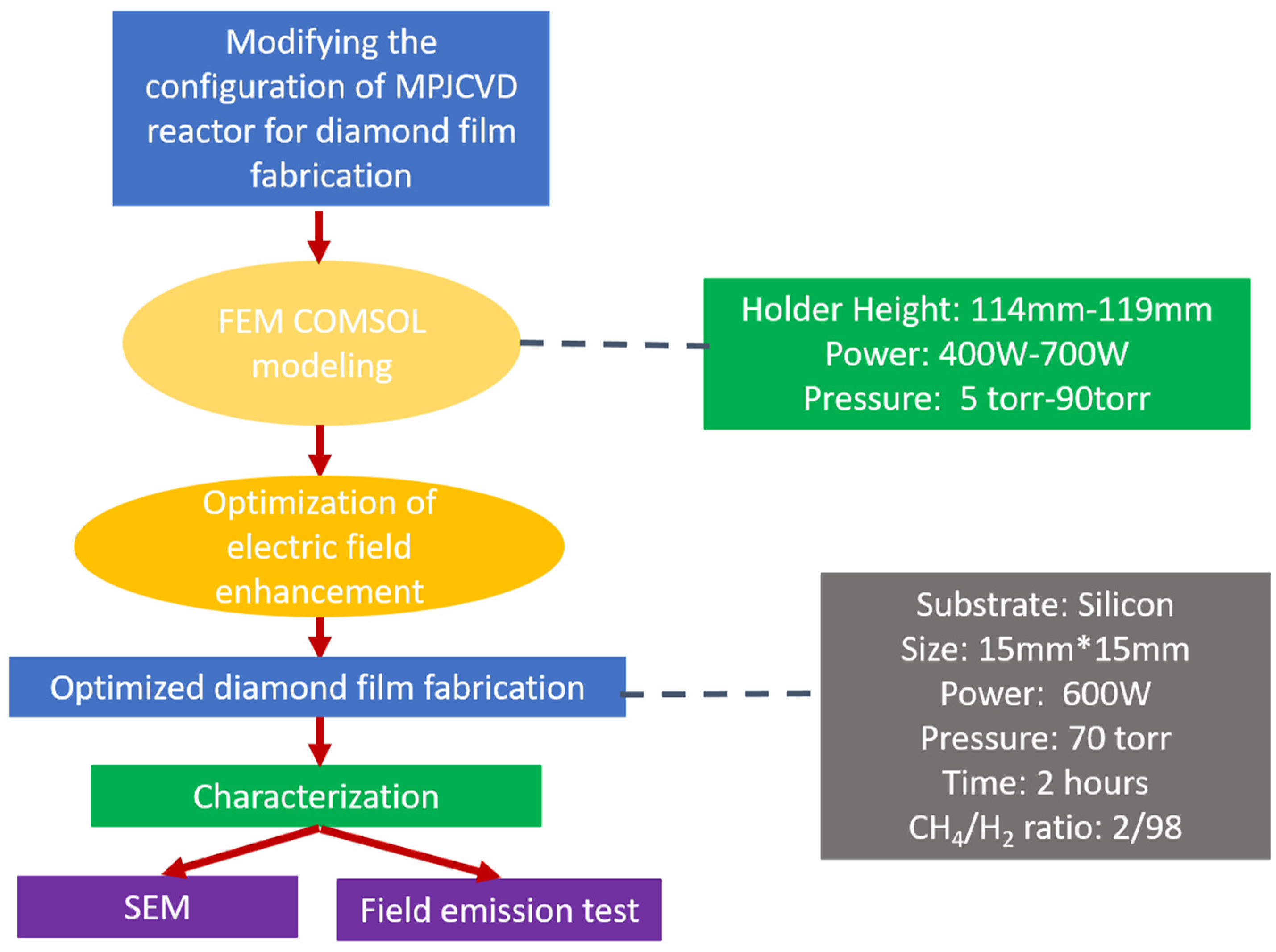
Numerical simulations of an MPJCVD system are essential to gain a deeper understanding of fabrication processes. These simulations enable the data collection and optimization of fabrication conditions, replacing difficult experimentation. However, modeling microwave plasmas at atmospheric pressure also has its difficulties, as it is a numerically stiff problem due to their high nonlinearity. In addition, plasma behavior spans wide ranges in both time and length scales. Therefore, the numerical study of microwave plasma is computationally expensive [31,32,33,34,35,36,37,38]. Figure 3 shows the full research flow for the optimization of the MPJCVD chamber configuration with FEM modeling. In this study, a complete three-dimensional MPJCVD model has been constructed to investigate various parameters such as reactor geometry, especially the sample holder, microwave power, and gas pressure [28,33]. The motivation is to gain more physical insight and a better understanding of the composition, spatial distributions, and plasma parameters under different operating conditions and a variety of gas pressures. Using the optimized simulation result, the growth of diamond film on different substrates has been successfully conducted. This experiment is based on the optimization simulation analysis of the chamber cavity with the sample holder. The scanning electron microscope (SEM) images have been taken to characterize the thin films to see the presence of a diamond film structure and the uniformity. The field emission properties of the MPJCVD fabrication diamond film grown on several substrates have been measured and compared in order to find a good cold cathode for field electron emission. The experimental results also serve as feedback to validate the numerical simulation model of the MPJCVD system. Both the numerical simulation and experimental studies of reconditioning the MPJCVD system play an essential role in successfully fabricating diamond films on a variety of substrates.

3. Formulation and Numerical Modeling

As mentioned above, plasma is a complex system involving nonlinear dynamics, particle-wave interactions, and chemical reactions on multiple spatial and time scales. In general, the motions of electrons and ions in a plasma, due to their large mass differences, have to be considered on different time scales, and electron transport should be described by the Boltzmann equation, which is a non-local continuity equation in a six-dimensional phase space. However, the Boltzmann equation is an extremely complicated integro-differential equation, and solving it in an efficient manner is difficult. To reduce the complexity, the Boltzmann equation can be approximated by fluid equations, multiplied by a weighting distribution function, and then integrated over velocity space, resulting in a three-dimensional, time-dependent fluid model. The fluid equations describe the electron number density, the mean electron momentum, and the mean electron energy as a function of space and time [42]. When the gas pressure is above about 1 Torr and the discharge is weakly ionized, the fluid or drift-diffusion (DD) approximation is suitable, and a Maxwellian distribution is assumed for the electron energy distribution function (EEDF). Based on the FEM simulations implemented using the commercial software COMSOL Multiphysics [43], the plasma, chemistry, and electromagnetic modules are coupled and tailor-made to model the low-temperature microwave plasma interaction in the MPJCVD system. These models help us to gain physical insight into plasma discharges and guide the performance of existing or potential designs, which will greatly benefit the applications of plasma technology in science and industry. Given their high degree of nonlinearity, plasma systems are highly complicated, and even a small change to the electrical input or plasma chemistry would significantly change the discharge characteristics. Modeling this behavior requires a high computational cost. The following subsections introduce the theory, governing equations, and numerical methods used in this work.

3.1. Governing Equations

In order to consider the microwave heating of plasmas in the MPJCVD system, the microwave plasma interface is employed as implemented in COMSOL. The electron dynamics are described by a pair of DD equations, one equation, for the electron density and one for the electron energy density, as follows [43]:
n e t + · Γ e = R e ,
n ϵ t + · Γ ϵ + E · Γ e = R ϵ + Q r h | q | ,
Here, n e is the electron density, n ϵ is electron energy density, Γ e is the electron flux, Γ ϵ is the electron energy flux, E is the quasi-static electric field, R e represents the electron source, R ϵ is the energy loss due to inelastic collisions, Q r h is the power transfer from the electromagnetic field to the electrons, and q is the electron charge. The electron flux Γ e and the electron energy flux Γ ϵ are defined explicitly as
Γ e = [ n e ( μ e · E ) D e · n e ]
Γ ϵ = [ n ϵ ( μ ϵ · E ) D ϵ · n ϵ ]
where μ e represents the electron mobility, μ ϵ is the electron energy mobility, D e is the electron diffusivity, and D ϵ is the electron energy diffusivity. They are related and calculated by
D e = μ e T e ,
μ ϵ = 5 3 μ e ,
D ϵ = μ ϵ T e .
where T e is the electron temperature. The source coefficients R e and R ϵ are determined by the plasma chemistry and are written using rate coefficients. Suppose that there are M reactions that contribute to the growth or decay of electron density and P inelastic electron-neutral collisions. The electron   source   R e and the energy loss due to inelastic collisions R ϵ are calculated respectively by
R e = i = 1 M x i k i N n n e ,
R ϵ = i = 1 P x i k i N n n e Δ ϵ i ,
where i is the reaction index, x i is the mole fraction of the target species for reaction i, k i is the rate coefficient for reaction i, N n is the total neutral number density, and Δ ϵ i is the energy loss due to reaction i. The rate coefficients can be computed from cross section data by the following integral:
k i = 2 | q | / m e 0 ϵ σ i ( ϵ ) f ( ϵ ) d ϵ ,
where ϵ is the energy, m e is the electron mass, σ i is the collision cross section for reaction i, f is the EEDF, which we assume is Maxwellian as mentioned above. The electron source and inelastic energy loss are automatically computed by the COMSOL multiphysics interface once the chemical species and reactions are chosen.
For non-electron species, the mass fraction w k of each species k can be solved by the convection-diffusion equation:
ρ t ( w k ) + ρ ( u · ) w k = · j k + R k .
The electrostatic field is calculated by solving the Poisson equation for the electrostatic or scalar potential V and taking a minus gradient of it, i.e., V :
· ( ε 0 ε r V ) = ρ ,
where ε 0 is the permittivity of vacuum and ε r is the relative permittivity of materials in the simulation domain, which usually has a spatial dependence. The space charge density ρ is computed based on the plasma chemistry using the equation below:
ρ = q ( k = 1 N Z k n k n e ) ,
where Z k is the charge and n k is the number density for species k.
In this fluid model, the electron transport and the motion of ionic and neutral species are solved by this set of equations in the time domain. The convection of electrons due to fluid motion is neglected.
For the microwave plasma interactions, due to the time scale difference between electron and ion motions, only electron heating by microwave is considered in the frequency domain. In the microwave plasma interface, the high frequency electric field E ¯ is computed using the Helmholtz equation:
× ( μ r 1 × E ¯ ) k 0 2 ( ε r j σ ω ε 0 ) E ¯ = 0 ,
where μ r is the relative permeability, assumed to be 1 in this work, k 0 is the wave number in the vacuum, ε r is the relative permittivity, the same as defined in the Poisson equation but assumed to be 1 for the plasma region, ω is the angular frequency of microwave, j is the unit of imaginary number, and σ is the plasma conductivity. The relationship between the plasma current density J p ¯ and the electric field E ¯ is defined as:
J p ¯ = σ E ¯ ,
and
σ = n e q 2 m e ( υ m + j ω ) ,
where υ m is the collision angular frequency of the electrons with background neutral gases. This formula is obtained by assuming a Maxwellian distribution function and taking the first moment of the Boltzmann equation, the mean momentum equation described above. One can refer to Ref. [43] for a more detailed derivation. Solving the Helmholtz equation with appropriate boundary conditions allows for the power transferred from the microwave to the electrons to be calculated by
Q r h = 1 2 Re ( J ¯ · E ¯ * ) ,
where J ¯ is the total current density, i.e., the plasma current plus the displacement current density, and * denotes the complex conjugate, and this microwave heating term is coupled back to the electron plasma fluid via Equation (2), and then the updated electron density n e is coupled to the Helmholtz equation, Equation (14), via the plasma conductivity σ in Equation (16), forming a self-consistent set of microwave plasma fluid models.

3.2. Numerical Methods

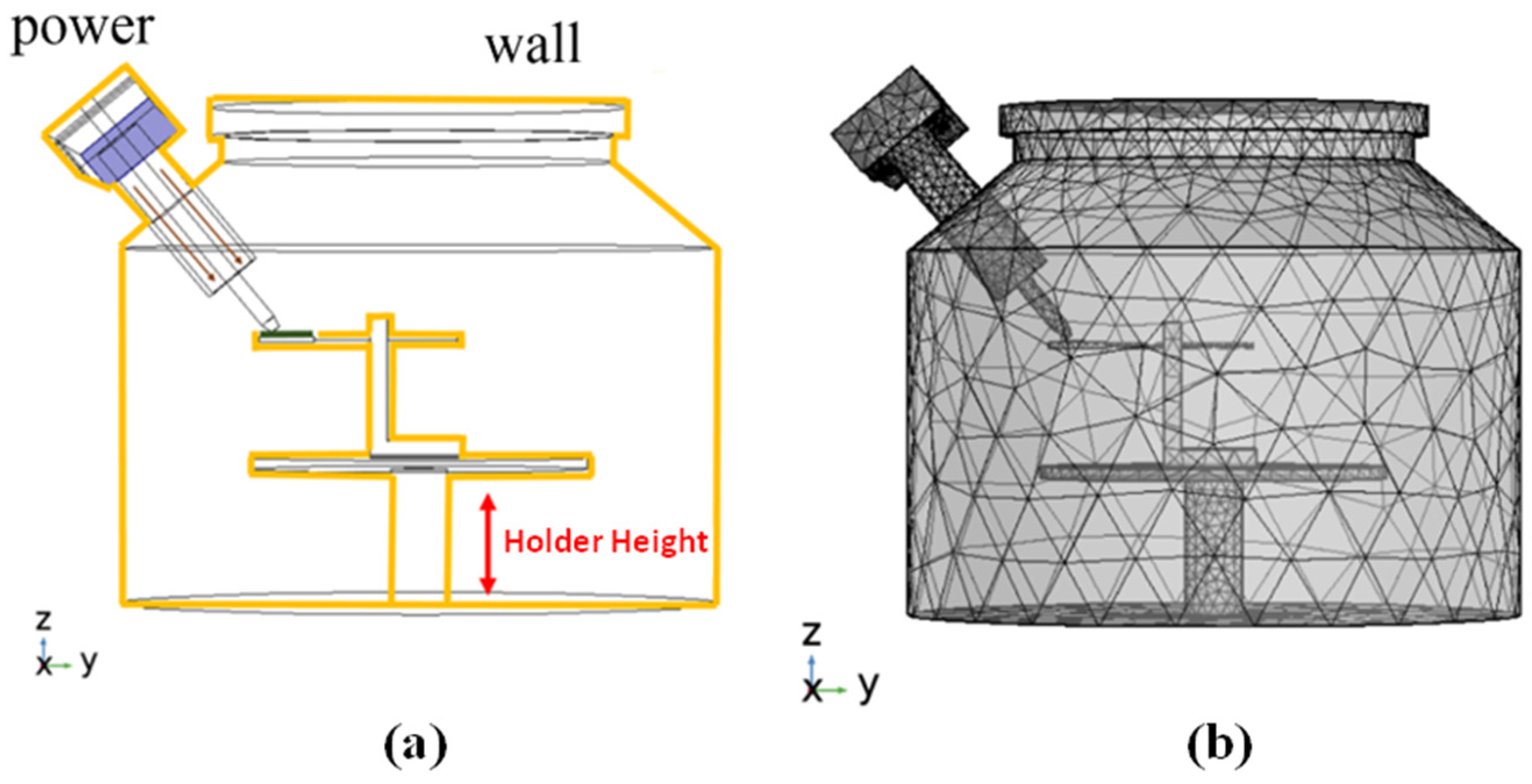
The governing equations are solved using the finite element method as implemented in the commercial software COMSOL Multiphysics. Figure 4 shows the whole simulation model of the MPJCVD system, which is constructed in a three-dimensional computational domain with reactor geometry and adaptive meshes. The height and radius of the chamber are 600 mm and 500 mm, respectively. There are a total of 68,256 meshes used in the simulations. Since the estimated result is focused on microwave coupling and plasma generation, the meshes are refined near the region from the waveguide to the substrate. The minimum size of the mesh is 0.00989 mm. The input power is set at 700 W via the port boundary condition in the electromagnetic wave interface, and the frequency used is 2.45 GHz. The pressure is set at 70 Torr, and the environment’s temperature is 1000 K. The initial electron density and electron energy are 10 13   m 3 and 4 eV, respectively. The electron mobility and electron diffusion coefficient are 4 × 10 2   m 2 / ( V · s ) and 4 × 10 2   m 2 / s , respectively.

4. Simulation Results and Optimization

The governing equations are solved using the adaptive finite element method as implemented in COMSOL Multiphysics. The effects of geometry, especially the height of the sample holder, input power, and gas pressure on the MPJCVD system will be discussed in the following subsection.

4.1. Effects of System Geometry

The optimized results use argon (Ar) molecules as the working gas to reduce computational expenses as plasma behavior is similar to those employing molecular gas species with complex chemical reactions. The reactions and collision formulas of argon are listed in Table 1.
In order to see the effects of system geometry, Figure 5 shows (a) the electron density, (b) the ion density, (c) the electric field, and (d) the electron temperature as functions of the height of the sample holder. It is apparent that the holder height significantly changes the plasma density. After analyzing the electric field, electron density, electron temperature, and ion density through COMSOL modeling, it is found that the distribution of energy inside the cavity is optimized at the stage height of 118 mm. The local electric fields at the antenna for different heights of the stage at the same microwave power of 700 W, the gas pressure of 70 Torr, and the microwave frequency of 2.45 GHz are compared. At a height of 118 mm, the electron and ion densities are relatively concentrated at 10 18   m 3 , while the electron temperature is 30 eV. Figure 6 shows the contours of electron density, ion density, electric field, and electric temperature for the optimized case.

4.2. Effects of Microwave Power

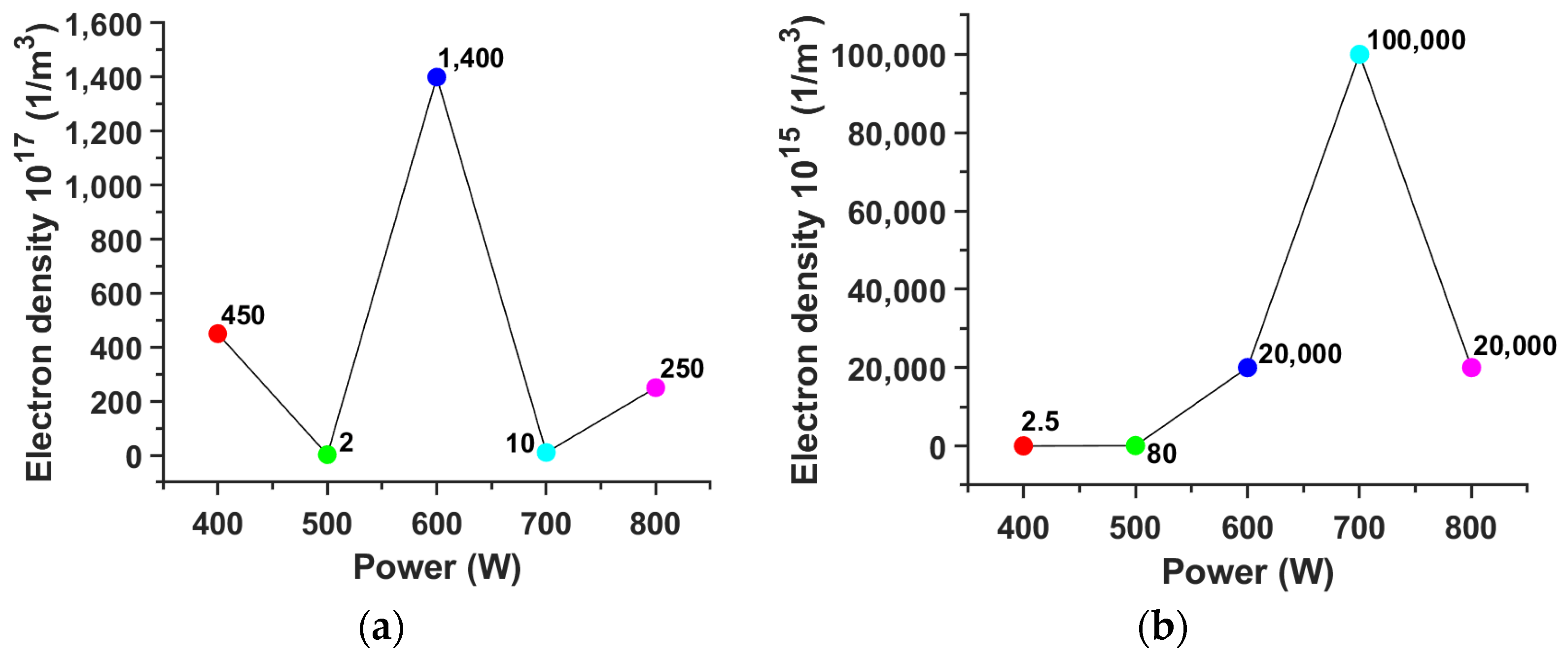
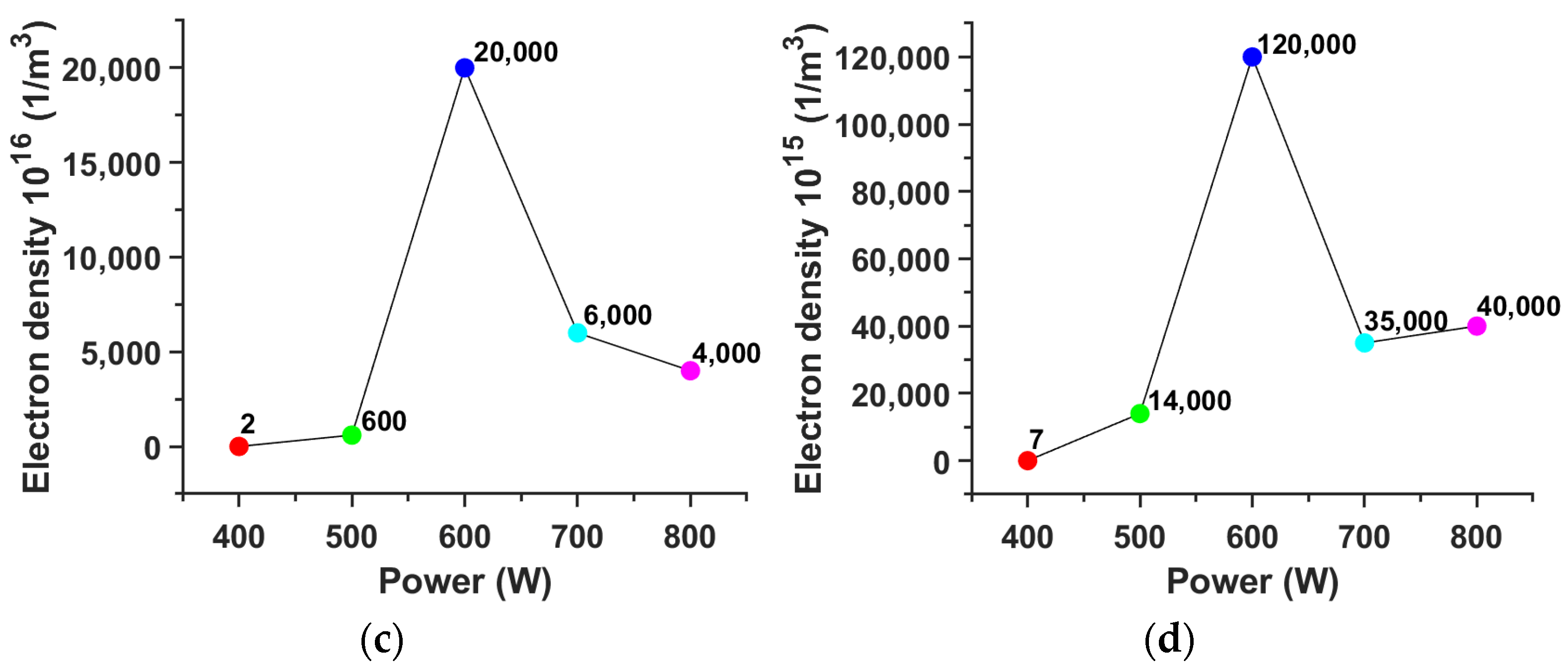
Figure 7 shows the electron density of the argon plasma at different microwave power levels for gas pressures of (a) 5 Torr, (b) 35 Torr, (c) 70 Torr, and (d) 90 Torr. It is found that at a pressure of 70 Torr and an input power of 600 W, the electron density can reach 2 × 10 20   m 3 .

4.3. Hydrogen Plasma

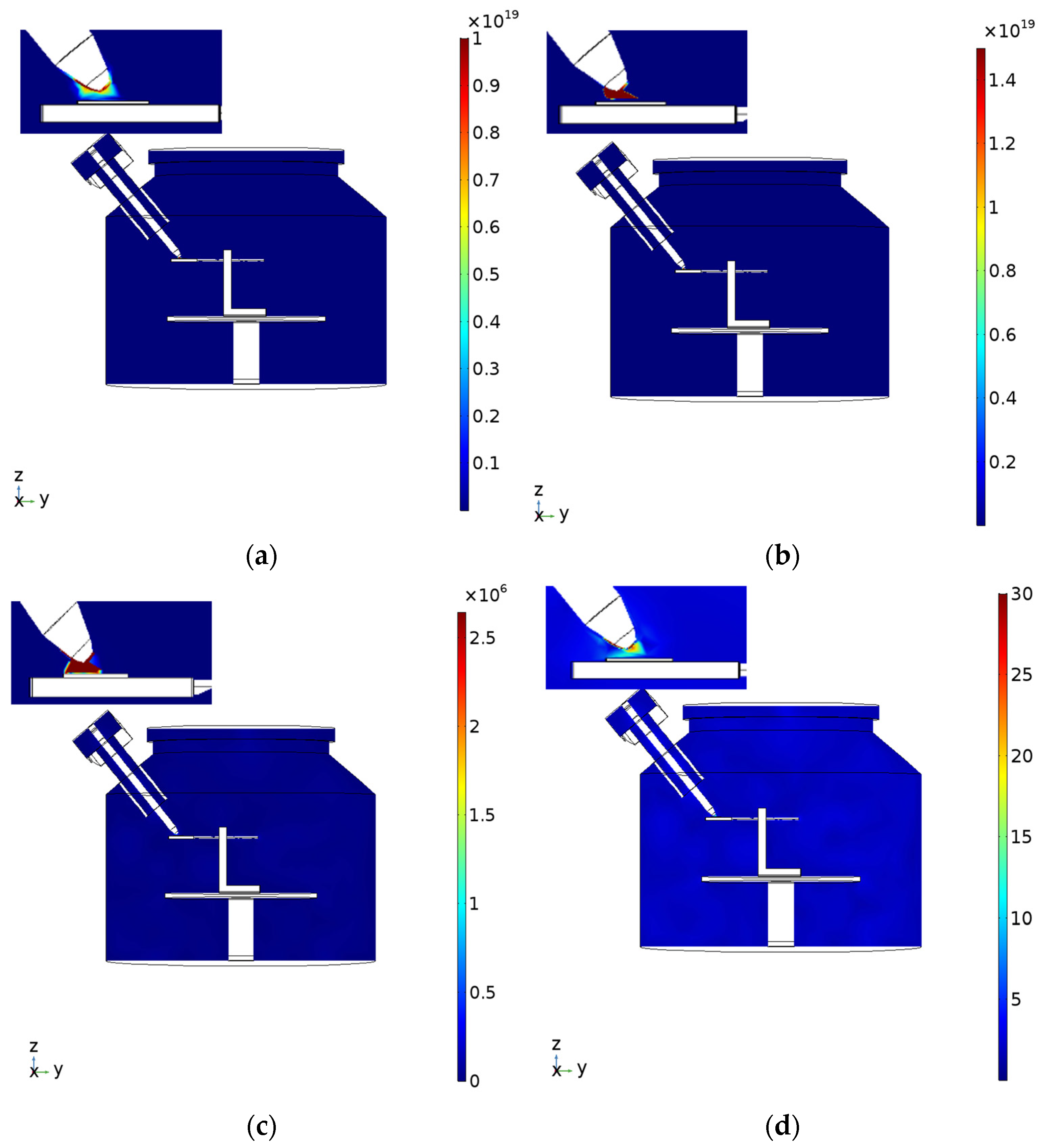
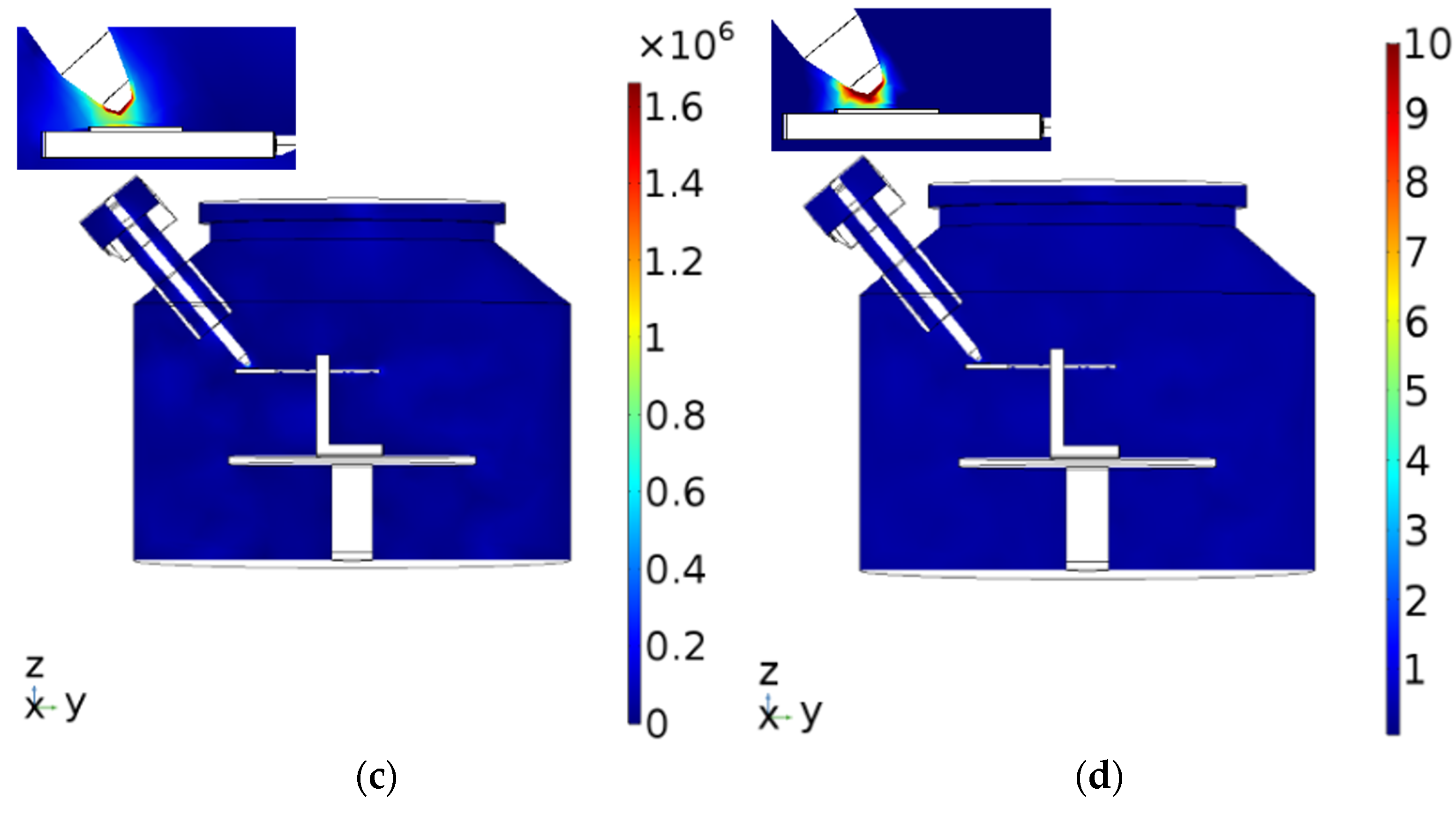
The simulation of hydrogen gas was also carried out at a stage height of 118 mm, a gas pressure of 70 Torr, and a microwave power of 600 W. The reactions and collision formulas of hydrogen are listed in Table 2. The results are shown in Figure 8, and the electric field intensity observed is 1.6 × 10 6 V/m, which is a very strong electric field concentrated at the tip of the antenna. The corresponding plasma density reaches 1.2 × 10 20   m 3 , concentrating at the tip of the antenna. The electron temperature is measured at 10 eV. The simulated hydrogen plasma is consistent with the actual experiment, as discussed below.

5. Experimental Results

The optimized hydrogen parameters, i.e., 600 W of power, 70 Torr of gas pressure, and 118 mm of stage height, are used in the diamond film fabrication. In the following, we describe the pretreatment, MPJCVD process, diamond film characterization, and field emission measurement.

5.1. Pretreatment

Prior to the MPJCVD process, the silicon (100) and graphite substrates need to be prepared. This substrate was placed in an acetone solution and treated with an ultrasonic cleaner for 15 min. The substrate was then placed in a methanol solution and treated with an ultrasonic cleaner for another 15 min without further residue cleaning. After that, the substrate was placed in a TiD (nano titanium and nanodiamond powder) solution for 30 min to induce crystal growth. Finally, nitrogen gas is used to dry the surface of the sample.

5.2. Microwave Plasma Jet Chemical Vapor Deposition of Diamond Films and Characterization

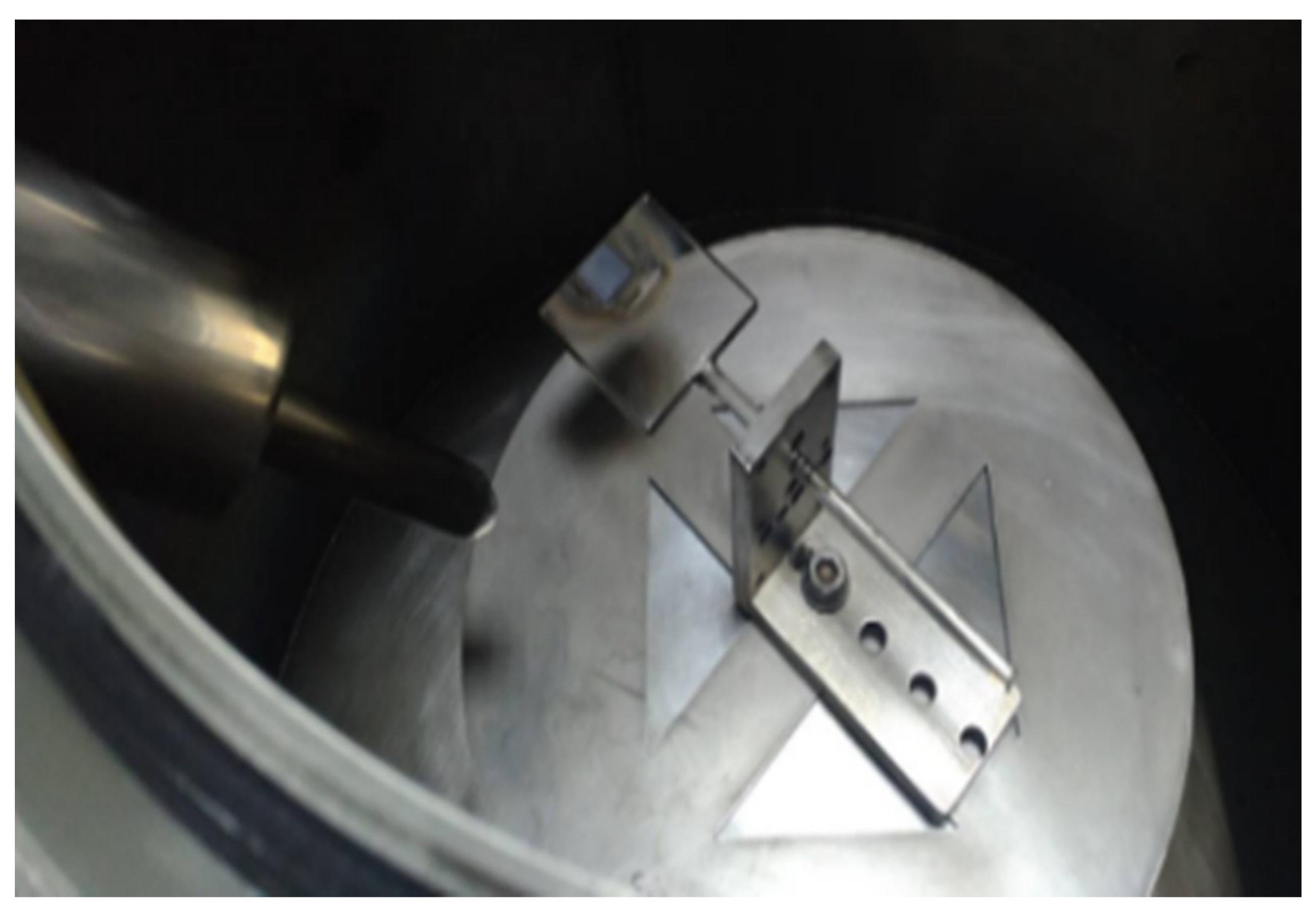
The treated graphite substrate was placed on the quartz stage in the MPJCVD chamber (see Figure 9) with the following operation settings: microwave power of 600 W at a frequency of 2.45 GHz, a gas pressure of 70 Torr, and a combination of hydrogen and methane gases (a methane concentration percentage of 0.25%) for two hours. To improve the uniformity of the deposited diamond film and increase the deposition rate, the geometry configuration was optimized to enhance the electron density, ion density, electric field, and electron temperature.
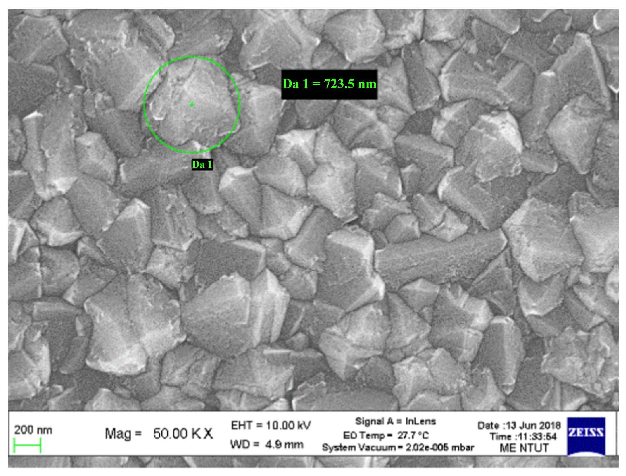
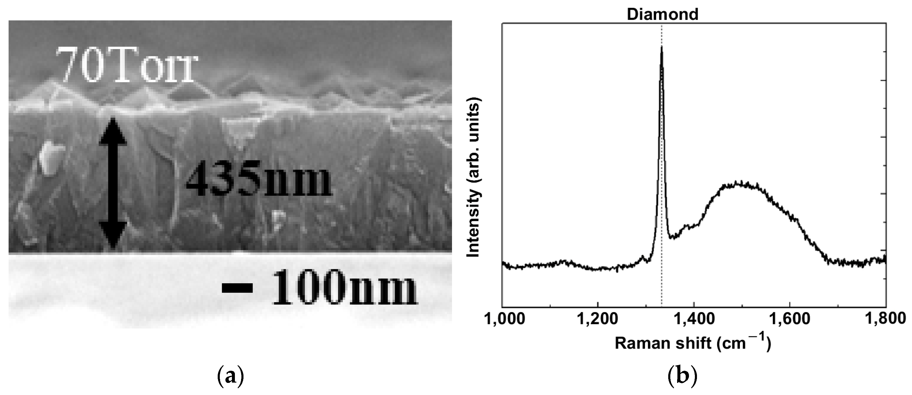
Finally, according to the optimal simulation parameters, the MPJCVD system is operating successfully. The scanning electron microscope is used to examine the surface morphology and microstructure of the diamond film. Figure 10 shows the SEM image of the diamond film grown on the graphite substrate with working gas containing 0.25% methane, exhibiting distributed particles with a size of ~1 μm. The film thickness is also measured with the SEM, as shown in Figure 11a, giving a uniform thickness of about 435 nm. Figure 11b shows the Raman spectroscopy of this fabricated diamond film, and as one can see clearly, the diamond (D) peak appears in the spectrum [44]. The SEM images reveal the presence of a diamond film uniformly distributed with particles of a size of ~1 μm. The deposited diamond film has relatively high uniformity and continuity.
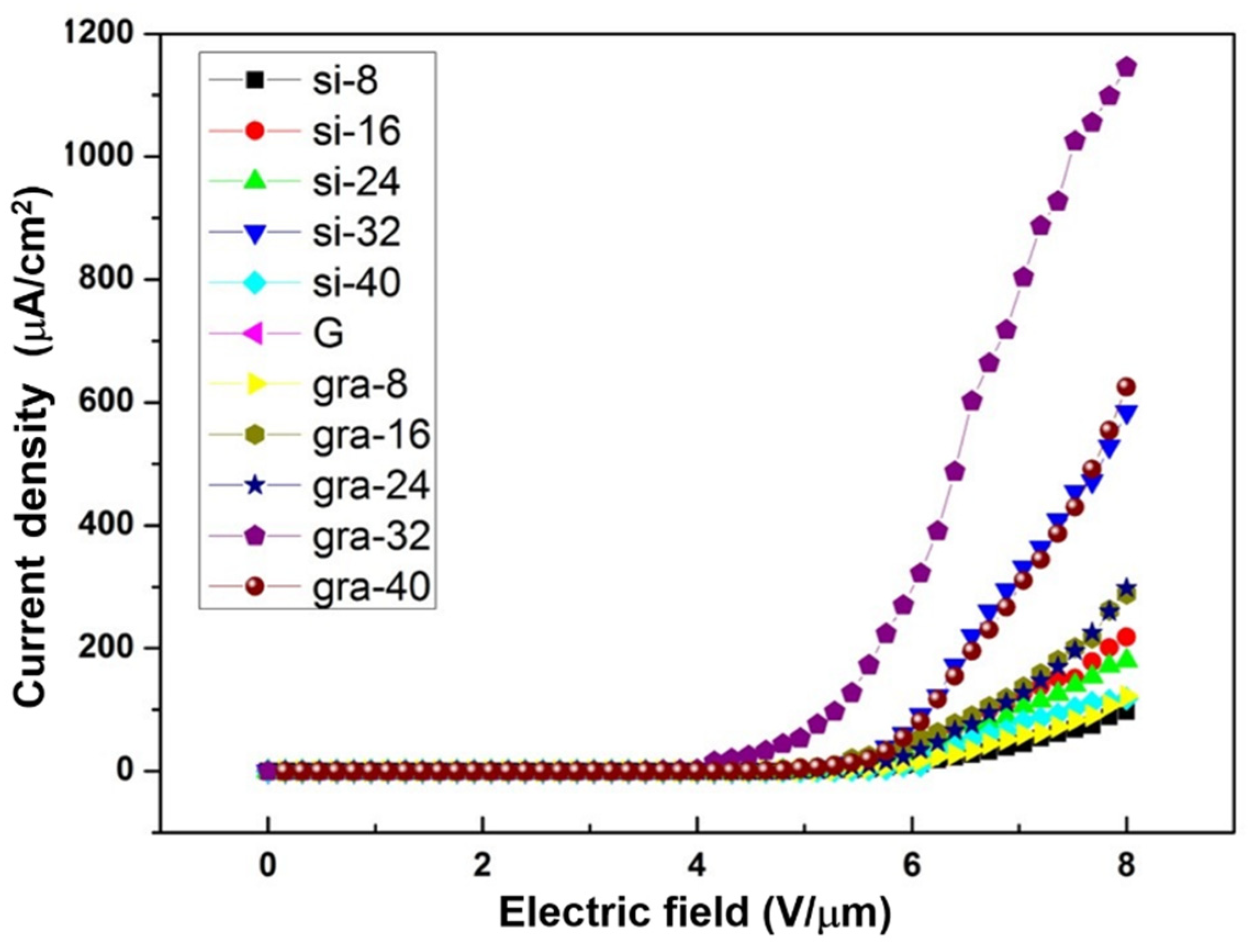
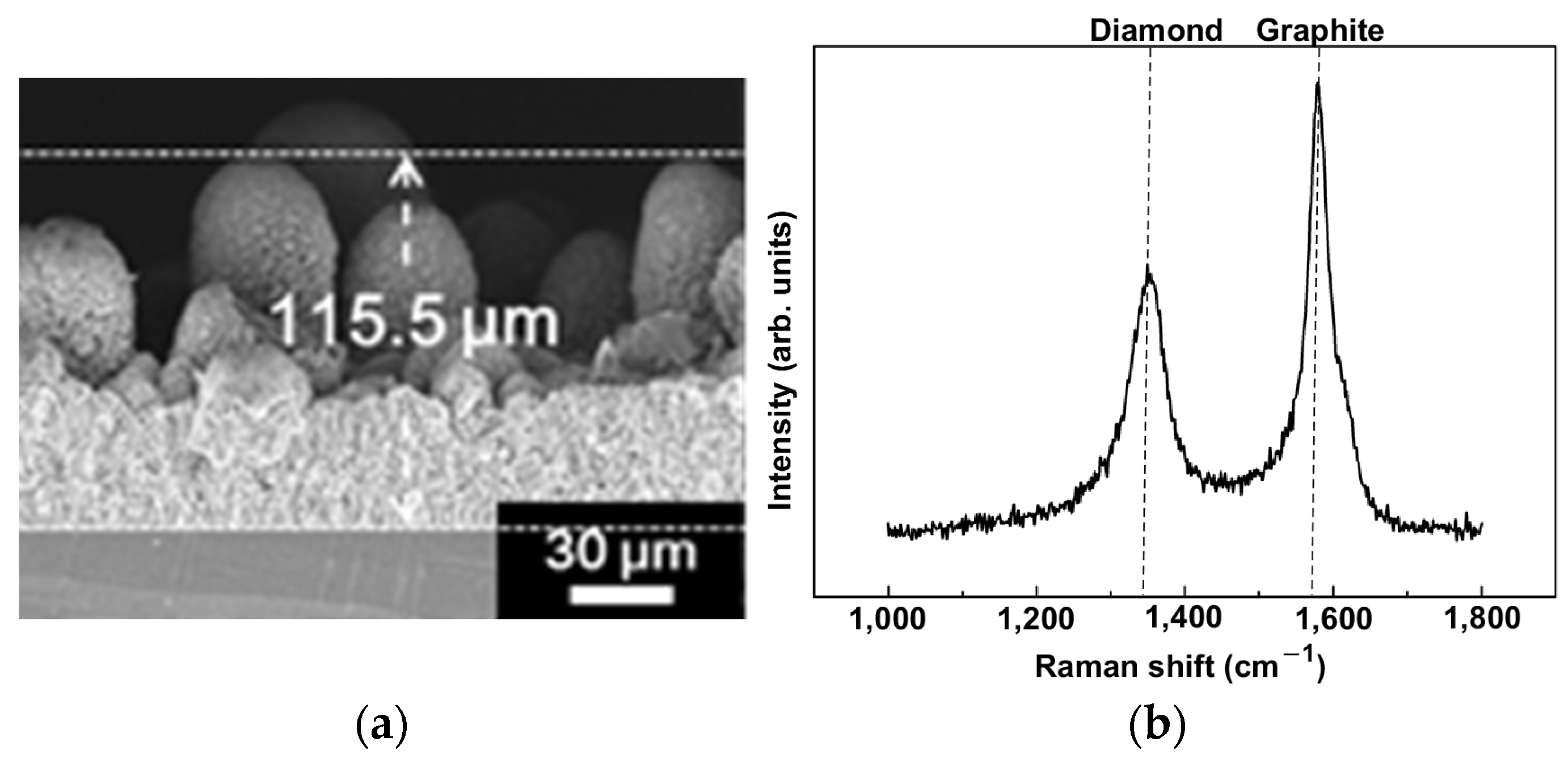
Using the same fabrication method and settings (microwave power of 600 W at a frequency of 2.45 GHz, a gas pressure of 70 Torr with a combination of CH4 and H2 gases), and the methane concentration changing from 8% to 40% at a step of 8%, diamond films are deposited on silicon and graphite substrates for 2 h. In addition to SEM analysis and examining surface morphology, electrical properties are also tested, and field emission from the diamond film grown from this MPJCVD system shows extraordinary properties, i.e., extremely low turn-on voltage and high current density. The field emission current densities from the diamond films fabricated under different conditions and measured at different electric fields are shown in Figure 12. The diamond film grown on the graphite substrate with a 32% methane concentration has the most significant electrical property. The turn-on electric field determined for this case is as low as 4 V/μm. Figure 13 shows the SEM images with (a) 300 X and (b) 50,000 X of the diamond film grown on the graphite substrate with working gas containing 32% methane. It is obvious that large particles with sizes ranging from 10s to 100 μm can be seen in Figure 13a, while a zoom in SEM in Figure 13b shows a graphite structure. As the sample exhibits extraordinary field emission properties, we further study the diamond film thickness and its composition. Figure 14a is the SEM image of the diamond film for thickness measurement, and the film thickness is around 115.5 μm. Figure 14b shows the Raman spectroscopy of the diamond film, and there are two main peaks found in the spectrum: in addition to the D (left) peak, which shows the presence of the diamond, one can clearly see a graphite (G) peak on the right side. These are identified as carbon nanopillars (CNPs) formed above the diamond film, and this might be due to the large dissociation of methane (32% methane), leading to the formation of C2 species and then causing the CNPs to be deposited [45]. The extraordinary field emission from this sample might be attributed to the combined effects of a good electrical contact from the diamond film grown on the graphite substrate and the field enhancement of the CNPs sitting on the diamond film.

6. Conclusions

The numerical modeling is employed to understand the operation of the MPJCVD system and optimize its geometry configuration and working conditions. The MPJCVD system with argon and hydrogen plasmas is modeled and simulated using FEM multiphysics modeling. It is found that, under optimal conditions, the plasmas are concentrated at the antenna tip after reconditioning, and the plasma generated in the MPJCVD system is consistent with the simulation results. Under the optimized operating conditions after reconditioning for fabrication, the SEM shows that the deposited diamond film has relatively high uniformity and continuity, and the size of the diamond particle is about 1 μm. In addition, by increasing methane up to 32% during the fabrication, our research shows that the turn-on electric field of the diamond film grown on the graphite substrate can be as low as 4 V/μm, and the corresponding field emission exhibits an extraordinarily high current density compared to other cases in this study. This might be attributed to the combined effects of a good electrical contact from the diamond film grown on the graphite substrate and the field enhancement of the CNPs sitting on the diamond film. The developed multiphysics model provides valuable physical insights into the MPJCVD system, which guided performance improvements. The diamond films developed by the MPJCVD can be beneficial for applications in surface hardening, and those grown on a graphite substrate might serve as bright field electron emission sources.

Author Contributions

Conceptualization, C.-R.L. and M.-C.L.; methodology, H.-Y.H. and M.-C.L.; software, C.-Y.L. and K.A.; validation, C.-Y.L. and C.-W.L.; formal analysis, C.-Y.L. and C.-W.L.; investigation, J.-S.Y. and C.-Y.L. and C.-W.L.; data curation, C.-Y.L., C.-W.L. and K.A.; writing—original draft preparation, J.-S.Y. and H.-Y.H.; writing—review and editing, H.-Y.H. and M.-C.L.; Supervision, C.-R.L. and J.-S.S.; project administration, H.-Y.H. and J.-S.S.; funding acquisition, C.-R.L. and J.-S.S. All authors have read and agreed to the published version of the manuscript.

Funding

This research was partially supported by the Ministry of Science and Technology (111-2221-E-027-075), the National Taipei University of Technology in Taiwan, Hanyang University (HY-201400000002393), and the National Research Foundation (2015R1D1A1A01061017) in the Republic of Korea.

Institutional Review Board Statement

Not applicable.

Informed Consent Statement

Not applicable.

Data Availability Statement

Data will be made available upon reasonable request.

Acknowledgments

The authors would like to acknowledge the financial support from the Ministry of Science and Technology (111-2221-E-027-075), the National Taipei University of Technology in Taiwan, Hanyang University (HY-201400000002393), and the National Research Foundation (2015R1D1A1A01061017) in the Republic of Korea.

Conflicts of Interest

The authors have no conflicts to disclose.

References

  1. Shokrieh, M.M.; Rafiee, R. A review of the mechanical properties of isolated carbon nanotubes and carbon nanotube composites. Mech. Compos. Mater. 2010, 46, 155–172. [Google Scholar] [CrossRef]
  2. Che, J.; Cagin, T.; Goddard, W.A., III. Thermal conductivity of carbon nanotubes. Nanotechnology 2000, 11, 65. [Google Scholar] [CrossRef]
  3. Hone, J.; Llaguno, M.C.; Nemes, N.M.; Johnson, A.T.; Fischer, J.E.; Walters, D.A.; Casavant, M.J.; Schmidt, J.; Smalley, R.E. Electrical and thermal transport properties of magnetically aligned single wall carbon nanotube films. Appl. Phys. Lett. 2000, 77, 666–668. [Google Scholar] [CrossRef]
  4. Zhou, D.; Krauss, A.R.; Qin, L.C.; McCauley, T.G.; Gruen, D.M.; Corrigan, T.D.; Chang, R.P.H.; Gnaser, H. Synthesis and electron field emission of nanocrystalline diamond thin films grown from N 2/CH4 microwave plasmas. J. Appl. Phys. 1997, 82, 4546–4550. [Google Scholar] [CrossRef]
  5. Bhattacharyya, S.; Auciello, O.; Birrell, J.; Carlisle, J.A.; Curtiss, L.A.; Goyette, A.N.; Gruen, D.M.; Krauss, A.R.; Schlueter, J.; Sumant, A.; et al. Synthesis and characterization of highly-conducting nitrogen-doped ultrananocrystalline diamond films. Appl. Phys. Lett. 2001, 79, 1441–1443. [Google Scholar] [CrossRef]
  6. Veres, M.; Tóth, S.; Koós, M. Grain boundary fine structure of ultrananocrystalline diamond thin films measured by Raman scattering. Appl. Phys. Lett. 2007, 91, 031913. [Google Scholar] [CrossRef]
  7. Lin, C.R.; Liao, W.H.; Wei, D.H.; Chang, C.K. Fabrication of nanogranular diamond films by MPJCVD system. Phys. Procedia. 2011, 18, 148–153. [Google Scholar] [CrossRef] [Green Version]
  8. Ginzburg, V.L. Propagation of Electromagnetic Waves in Plasmas; North Holland Publishing Company: Amsterdam, The Netherlands, 1961. [Google Scholar]
  9. Selwyn, G.S.; Herrmann, H.W.; Park, J.; Henins, I. Materials Processing Using an Atmospheric Pressure, RF-Generated Plasma Source. Contrib. Plasma Phys. 2001, 41, 610–619. [Google Scholar] [CrossRef]
  10. Schutze, A.; Jeong, J.Y.; Babayan, S.E.; Park, J.; Selwyn, G.S.; Hicks, R.F. The atmospheric-pressure plasma jet: A review and comparison to other plasma sources. IEEE Trans. Plasma Sci. 1998, 26, 1685–1694. [Google Scholar] [CrossRef] [Green Version]
  11. Kruger, C.H.; Owano, T.G.; Laux, C. Experimental investigation of atmospheric pressure nonequilibrium plasma chemistry. IEEE Trans. Plasma Sci. 1997, 25, 1042–1051. [Google Scholar] [CrossRef]
  12. Kim, H.J.; Hong, S.H. Comparative measurements on thermal plasma jet characteristics in atmospheric and low pressure plasma sprayings. IEEE Trans. Plasma Sci. 1995, 23, 852–859. [Google Scholar]
  13. Hoffmann, H. O--ion radiation in the spectrum of an oxygen arc plasma. J. Quant. Spectrosc. Radiat. Transf. 1979, 21, 163–180. [Google Scholar] [CrossRef]
  14. Eliasson, B.; Kogelschatz, U. Nonequilibrium volume plasma chemical processing. IEEE Trans. Plasma Sci. 1991, 19, 1063–1077. [Google Scholar] [CrossRef]
  15. Eliasson, B.; Kogelschatz, U. Modeling and applications of silent discharge plasmas. IEEE Trans. Plasma Sci. 1991, 19, 309–323. [Google Scholar] [CrossRef]
  16. Massines, F.; Rabehi, A.; Decomps, P.; Gadri, R.B.; Ségur, P.; Mayoux, C. Experimental and theoretical study of a glow discharge at atmospheric pressure controlled by dielectric barrier. J. Appl. Phys. 1998, 83, 2950–2957. [Google Scholar] [CrossRef]
  17. Tsai, P.P.; Wadsworth, L.C.; Roth, J.R. Surface modification of fabrics using a one-atmosphere glow discharge plasma to improve fabric wettability. Text. Res. J. 1997, 67, 359–369. [Google Scholar] [CrossRef]
  18. Kanazawa, S.; Kogoma, M.; Moriwaki, T.; Okazaki, S. Stable glow plasma at atmospheric pressure. J. Phys. D. Appl. Phys. 1988, 21, 838. [Google Scholar] [CrossRef]
  19. Moravej, M.; Yang, X.; Barankin, M.; Penelon, J.; Babayan, S.E.; Hicks, R.F. Properties of an atmospheric pressure radio-frequency argon and nitrogen plasma. Plasma Sources Sci. Technol. 2006, 15, 204. [Google Scholar] [CrossRef]
  20. Moon, S.Y.; Choe, W.; Kang, B.K. A uniform glow discharge plasma source at atmospheric pressure. Appl. Phys. Lett. 2004, 84, 188–190. [Google Scholar] [CrossRef]
  21. Han, K.H.; Kang, J.G.; Uhm, H.S.; Kang, B.K. Photo-resist ashing by atmospheric pressure glow discharge. Curr. Appl. Phys. 2007, 7, 211–214. [Google Scholar] [CrossRef]
  22. Woskov, P.P.; Rhee, D.Y.; Thomas, P.; Cohn, D.R.; Surma, J.E.; Titus, C.H. Microwave plasma continuous emissions monitor for trace-metals in furnace exhaust. Rev. Sci. Instrum. 1996, 67, 3700–3707. [Google Scholar] [CrossRef] [Green Version]
  23. Woskov, P.P.; Hadidi, K. Large electrodeless plasmas at atmospheric pressure sustained by a microwave waveguide. IEEE Trans. Plasma Sci. 2002, 30, 156–157. [Google Scholar] [CrossRef]
  24. Al-Shamma’a, A.I.; Wylie, S.R.; Lucas, J.; Yan, J.D. Atmospheric microwave plasma jet for material processing. IEEE Trans. Plasma Sci. 2002, 30, 1863–1871. [Google Scholar] [CrossRef]
  25. Wylie, S.R.; Al-Shamma’a, A.I.; Lucas, J. Microwave plasma system for material processing. IEEE Trans. Plasma Sci. 2005, 33, 340–341. [Google Scholar] [CrossRef]
  26. Song, H.; Hong, J.M.; Lee, K.H.; Choi, J.J. Stable microwave coaxial cavity plasma system at atmospheric pressure. Rev. Sci. Instrum. 2008, 79, 054702. [Google Scholar] [CrossRef]
  27. Harigai, T.; Ohhra, H.; Tominaga, R.; Bando, T.; Takikawa, H.; Kunitsugu, S.; Gonda, H. Ultra-high-rate deposition of diamond-like carbon films using Ar/C2H2 plasma jet CVD in combination with substrate-stage discharge. Jpn. J. Appl. Phys. 2022, 61, SI1001. [Google Scholar] [CrossRef]
  28. Huang, Y.; Chen, L.; Shao, S.; Huang, K.; An, K.; Zheng, Y.; Liu, J.; Wei, J.; Li, C. The 7-in. freestanding diamond thermal conductive film fabricated by DC arc Plasma Jet CVD with multi-stage magnetic fields. Diam. Relat. Mater. 2022, 122, 108812. [Google Scholar] [CrossRef]
  29. Huang, Y.; Chen, L.; Shao, S.; Zhu, X.; Huang, K.; An, K.; Zheng, Y.; Liu, J.; Wei, J.; Li, C. Impact of deposition temperature on microstructure and properties of erbium oxide antireflective films deposited on CVD diamond substrates. Vacuum 2021, 193, 110547. [Google Scholar] [CrossRef]
  30. Zheng, Y.; Li, C.; Liu, J.; Wei, J.; Ye, H. Diamond with nitrogen: States, control, and applications. Funct. Diam. 2022, 1, 63–82. [Google Scholar] [CrossRef]
  31. Brezmes, A.O.; Breitkopf, C. Fast and reliable simulations of argon inductively coupled plasma using COMSOL. Vacuum 2015, 116, 65–72. [Google Scholar] [CrossRef]
  32. Shivkumar, G.; Tholeti, S.S.; Alrefae, M.A.; Fisher, T.S.; Alexeenko, A.A. Analysis of hydrogen plasma in a microwave plasma chemical vapor deposition reactor. J. Appl. Phys. 2016, 119, 113301. [Google Scholar] [CrossRef]
  33. Massaro, A.; Velardi, L.; Taccogna, F.; Cicala, G. Experimental and numerical studies of microwave-plasma interaction in a MWPECVD reactor. AIP Adv. 2016, 6, 125001. [Google Scholar] [CrossRef] [Green Version]
  34. Meyyappan, M. A review of plasma enhanced chemical vapour deposition of carbon nanotubes. J. Phys. D. Appl. Phys. 2009, 42, 213001. [Google Scholar] [CrossRef]
  35. Hassouni, K.; Silva, F.; Gicquel, A. Modelling of diamond deposition microwave cavity generated plasmas. J. Phys. D. Appl. Phys. 2010, 43, 153001. [Google Scholar] [CrossRef]
  36. Hassouni, K.; Grotjohn, T.A.; Gicquel, A. Self-consistent microwave field and plasma discharge simulations for a moderate pressure hydrogen discharge reactor. J. Appl. Phys. 1999, 86, 134–151. [Google Scholar] [CrossRef]
  37. Füner, M.; Wild, C.; Koidl, P. Numerical simulations of microwave plasma reactors for diamond CVD. Surf. Coat. Technol. 1995, 74, 221–226. [Google Scholar] [CrossRef]
  38. An, K.; Yu, S.W.; Li, X.J.; Shen, Y.Y.; Zhou, B.; Zhang, G.J.; Liu, X.P. Microwave plasma reactor with conical-reflector for diamond deposition. Vacuum 2015, 117, 112–120. [Google Scholar] [CrossRef]
  39. Wang, Q.; Wu, G.; Liu, S.; Gan, Z.; Yang, B.; Pan, J. Simulation-Based Development of a New Cylindrical-Cavity Microwave-Plasma Reactor for Diamond-Film Synthesis. Crystals 2019, 9, 320. [Google Scholar] [CrossRef] [Green Version]
  40. Salgado-Meza, M.; Martínez-Rodríguez, G.; Tirado-Cantú, P.; Montijo-Valenzuela, E.E.; García-Gutiérrez, R. Synthesis and Properties of Electrically Conductive/Nitrogen Grain Boundaries Incorporated Ultrananocrystalline Diamond (N-UNCD) Thin Films Grown by Microwave Plasma Chemical Vapor Deposition (MPCVD). Appl. Sci. 2021, 11, 8443. [Google Scholar] [CrossRef]
  41. Wang, B.; Yang, D.; Zhu, X.; Zhao, Y.; Wang, S.; Zhu, J.; Zhai, M. Effect of Positive Bias and Pressure on Plasma Flow Characteristics in a Chemical Vapor Deposition Chamber. Processes 2022, 10, 2665. [Google Scholar] [CrossRef]
  42. Lieberman, M.A.; Lichtenberg, A.J. Principles of Plasma Discharges and Materials Processing, 2nd ed.; John Wiley & Sons, Inc.: Hoboken, NJ, USA, 2005. [Google Scholar]
  43. COMSOL. The COMSOL Multiphysics 5.2 Release User’s Guide; COMSOL: Burlington, MA, USA, 2016. [Google Scholar]
  44. Lin, C.; Liao, W.; Wei, D.; Chang, C.; Fang, W.; Chen, C.; Dong, C.; Chen, J.; Guo, J. Improvement on the synthesis technique of ultrananocrystalline diamond films by using microwave plasma jet chemical vapor deposition. J. Cryst. Growth 2011, 326, 212. [Google Scholar] [CrossRef]
  45. Gromov, D.; Borgardt, N.; Grishina, Y.; Dedkova, A.; Kirilenko, E.; Dubkov, S. Study of growth kinetics of amorphous carbon nanopillars formed by PECVD. Proc. SPIE 2014, 9440, 89–97. [Google Scholar]
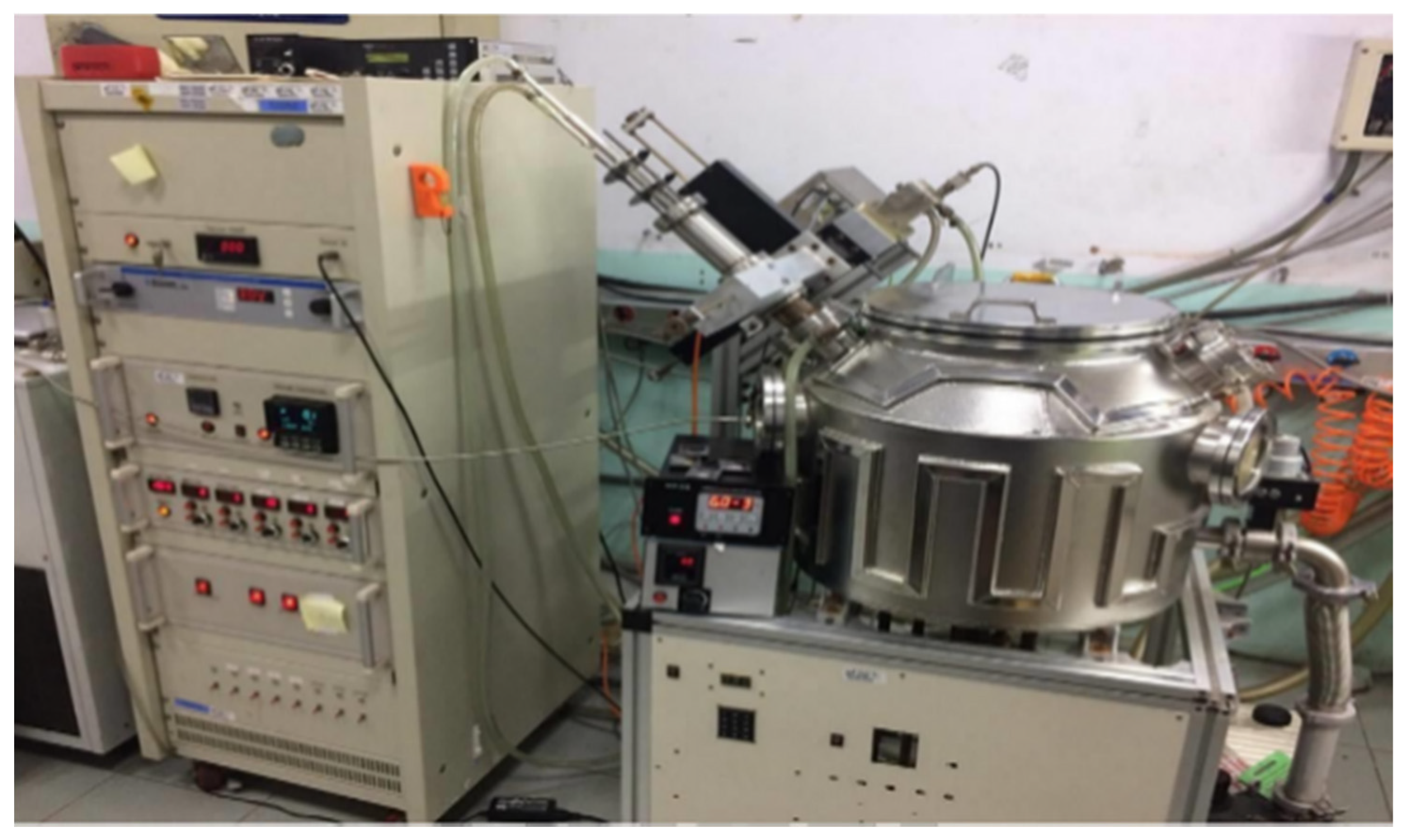
Figure 1. Experimental setup for diamond film fabrication using the microwave plasma jet chemical vapor deposition (MPJCVD) system.
Applsci 13 02531 g001
Figure 2. Schematics of the microwave plasma jet chemical vapor deposition (MPJCVD) system, in which the sample holder can be adjusted or modified.
Applsci 13 02531 g002
Figure 3. Research flow for the optimization of the MPJCVD chamber configuration with the FEM modeling for diamond film fabrication and characterization.
Applsci 13 02531 g003
Figure 4. (a) Reactor geometry and (b) the FEM adaptive meshing of the MPJCVD system.
Applsci 13 02531 g004
Figure 5. (a) Electron density, (b) ion density, (c) electric field, and (d) electron temperature are plotted as functions of the sample holder height at a microwave power of 700 W and gas pressure of 70 Torr in the MPJCVD system.
Applsci 13 02531 g005
Figure 6. Distribution of (a) electron density, (b) ion density, (c) electric field, and (d) electron temperature at the sample holder height of 118 mm, microwave power of 600 W, and argon gas pressure of 70 Torr in the MPJCVD system.
Applsci 13 02531 g006
Figure 7. Electron density of the argon plasma as a function of microwave power level for gas pressures of (a) 5 Torr, (b) 35 Torr, (c) 70 Torr, and (d) 90 Torr.
Applsci 13 02531 g007aApplsci 13 02531 g007b
Figure 8. Distribution of (a) electron density, (b) ion density, (c) electric field, and (d) electron temperature at the sample holder height of 118 mm, microwave power of 600 W, and hydrogen gas pressure of 70 Torr in the MPJCVD system.
Applsci 13 02531 g008aApplsci 13 02531 g008b
Figure 9. Photo image of the sample holder stage and antenna.
Applsci 13 02531 g009
Figure 10. SEM image of the diamond film, exhibiting distributed particles with a size of ~1 μm.
Applsci 13 02531 g010
Figure 11. Measurement of (a) the film thickness and (b) Raman spectroscopy of the diamond film grown on the graphite substrate with working gas containing 0.25% methane.
Applsci 13 02531 g011
Figure 12. Field emission characteristics: the current density as a function of an applied electric field for diamond films grown on silicon or graphite substrates in a range of methane concentration (8–40%).
Applsci 13 02531 g012
Figure 13. SEM image with (a) 300 X and (b) 50,000 X of the diamond film grown on the graphite substrate with working gas containing 32% methane.
Applsci 13 02531 g013
Figure 14. Measurement of (a) the film thickness and (b) Raman spectroscopy of the diamond film grown on the graphite substrate with working gas containing 32% methane.
Applsci 13 02531 g014
Table 1. Collisions and chemical reactions of argon (Ar) used in the MPJCVD model.
Formulas
1 e + Ar e + Ar
2 e + Ar e + Ar *
3 e + Ar 2 e + Ar +
4 e + Ar * 2 e + Ar +
5 e + Ar * e + Ar
6 Ar * + Ar * e + Ar + Ar +
7 Ar * + Ar e + Ar + Ar
Table 2. Collisions and chemical reactions of hydrogen (H) used in the MPJCVD model.
Formulas
1 e + H e + H
2 e + H e + H *
3 e + H * e + H
4 e + H 2 e + H +
5 H * + H * e + H + H +
Disclaimer/Publisher’s Note: The statements, opinions and data contained in all publications are solely those of the individual author(s) and contributor(s) and not of MDPI and/or the editor(s). MDPI and/or the editor(s) disclaim responsibility for any injury to people or property resulting from any ideas, methods, instructions or products referred to in the content.