Article

Fault Diagnosis of HV Cable Metal Sheath Grounding System Based on LSTM

School of Electric and Control Engineering, North China University of Technology, Beijing 100144, China
*
Author to whom correspondence should be addressed.
Appl. Sci. 2023, 13(4), 2453; https://doi.org/10.3390/app13042453
Submission received: 14 January 2023 / Revised: 1 February 2023 / Accepted: 13 February 2023 / Published: 14 February 2023
(This article belongs to the Section Electrical, Electronics and Communications Engineering)

Abstract

:

Featured Application

Authors are encouraged to provide a concise description of the specific application or a potential application of the work. This section is not mandatory.

Abstract

At present, the metal sheath of high voltage (HV) cables generally adopts the cross-bonded grounding method, which brings many types of faults and challenges the monitoring and diagnosis of the operation status of the cables. In order to effectively diagnose various types of faults in the metal sheath grounding system of HV cables, this paper proposes a fault diagnosis method for the metal sheath grounding system of HV cables based on long and short-term memory (LSTM). Firstly, the grounding system model of HV cable metal sheath is established. Secondly, the sheath currents of four faults are analyzed. Based on the sheath current amplitude ratio and phase difference of the same loop and the same grounding box, 14 feature vectors reflecting the operation state of the metal sheath grounding system are constructed. Then, the operation state of 18 kinds of metal sheath grounding systems is simulated, and the fault database is established. Finally, the LSTM algorithm is used to accurately identify the fault of HV cable grounding system. The results show that the LSTM algorithm can effectively diagnose and identify the faults of the HV cable metal sheath grounding system, and the accuracy rate is 100%.

1. Introduction

With the rapid development of urbanization, cross-linked polyethylene (XLPE) cables with good electrical performance are widely used in transmission and distribution networks. The safe and reliable operation of HV cables plays an important role in the stability of transmission and distribution networks; therefore, it is necessary to monitor and diagnose the operating status of HV cables [1,2,3,4].
HV cables commonly use metal sheath grounding to isolate the internal field strength of the cable from the outside world, and the sheath grounding method mainly includes single-ended grounding, double-ended grounding, and cross-bonded grounding [5]. According to the relevant provisions of the GB50217-2007, the line distance is short, the induced voltage is not greater than 50 V, and the choice of single-ended grounding. When the line is long, the single-ended grounding method cannot meet the above requirements. For cables below 35 kV or cables above 35 kV with smaller transmission capacity, double-ended grounding is selected. Cross-bonded grounding is mostly used for 35 kV and above, medium and long-distance transmission cables [6]. The use of cross-bonded grounding for HV cables can effectively reduce and suppress sheath currents, reduce additional losses in the cable, and improve the service life of the cable [7,8].
State Grid Corporation of China (SGCC) corporate standard Q/GDW 11316-2014 states that single-core cable line grounding current should meet the following requirements at the same time: the absolute value of grounding current <100 A; the ratio of grounding current to load current <20%, no significant change compared with historical data; the ratio of maximum to minimum single-phase grounding current <3″, [9]. The standard is relatively single and cannot directly reflect the connection between grounding current and grounding system fault. At present, scholars at home and abroad have made some research results on fault diagnosis of HV cable cross-bonded grounding systems. Yuan Yanling et al. [10] established an HV cable sheath circuit model and analyzed the change of sheath current of coaxial cable monitoring in cross-bonded box under sheath circuit open circuit, link box flooding, and joint epoxy prefabricated breakdown fault, based on this, a set of diagnostic criteria is proposed for the diagnosis and location of cable faults, but involved fewer fault types and lacked a comprehensive classification of grounding system faults. Du Boxue et al. [11] built the sheath current calculation software, which can calculate the sheath current, and compare the calculated value of cable sheath current with the actual measured value under different load operations throughout the day, and the deviation between them is more than 10%, then the cable may be determined to have insulation fault; however, the diagnostic accuracy of this method is not accurate enough, and it is easy to have a false alarm and missed alarm. It is proposed that sheath circulating currents can be used for sheath fault diagnosis. Examining the possibility of detecting cable sheath faults in HV and ultra-high-voltage (UHV) cable sheath cross-bonded systems by monitoring sheath-to-ground currents at the connection end [12]. By collecting the sheath currents at the first and last ends of the HV cable grounding system and constructing a two-dimensional Lissajous graph, the obtained feature parameters include the long axis length, short axis length, eccentricity, rate of change of tilt angle, and sheath currents at the first and last ends of the cable in a total of 6-dimensional feature vectors to diagnose cable sheath faults [13]. However, the method has high sampling requirements for the acquisition device and the data analysis is complicated, which is difficult to be applied to engineering practice.
To sum up, the various types of diagnostic schemes proposed have good diagnostic effects in their respective ranges and are not able to diagnose faults outside the range quickly and accurately. After comparing with the existing diagnostic methods in Table 1, this paper proposes a fault diagnosis method based on the LSTM algorithm for metal sheath grounding systems of HV cables is proposed. Firstly, a model of HV cable grounding system is established. Secondly, the sheath currents of four types of faults, namely, open circuit in sheath loop, the breakdown of cable joint, the flooding in link box, and the sheath grounding fault, are analyzed, and 14 feature vectors are constructed based on the amplitude ratio and phase difference of the sheath currents of the same circuit and the same grounding box to comprehensively reflect the operation status of the metal sheath grounding system. Then, 18 types of metal sheath grounding systems were simulated and operated to establish a fault database, and finally, the faults of HV cable grounding systems were intelligently and accurately identified by the LSTM algorithm.

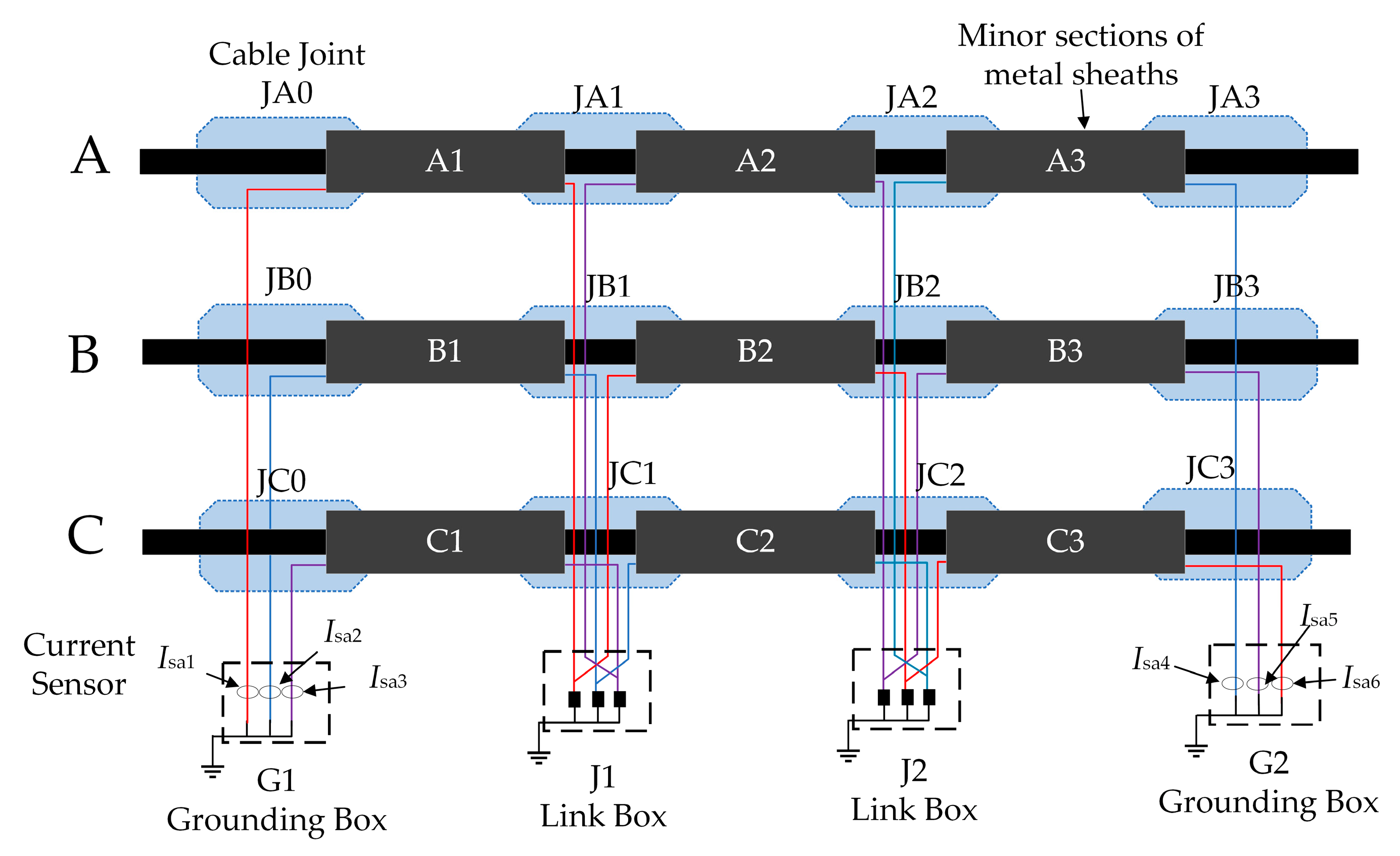
2. Model of High Voltage Cable Grounding System

The metal sheath of HV cable grounding system adopts the cross-bonded grounding method, which can effectively weaken the induced voltage on the sheath and thus can have the induction current on the sheath suppressed. The model of HV cable grounding system is shown in Figure 1.
As shown in Figure 1, the HV cable grounding system model is mainly composed of 12 cable joints (JA0, JA1, …, JC3), 9 minor sections of metal sheath (A1, A2, …, C3), and two link boxes (J1, J2) and two grounding boxes (G1, G2). Isan (n = 1, 2, 3, 4, 5, 6) indicates the sheath current flowing into the grounding box at the first and last ends. The metal sheaths are connected by coaxial cables transposed in the link box to form three sheath loops L1 (A1-B2-C3), L2 (B1-C2-A3), and L3 (C1-A2-B2), as shown in Figure 2. The sheath current is the current flowing through the metal sheath loops, including leakage current and sheath induced current.

2.1. Leakage Current

The leakage current is caused by the potential difference between the cable core and the metal sheath when the cable is in operation [13]. HV cables use XLPE as the material of the main insulation layer, whose impedance is much larger than the capacitive resistance between the core and the metal sheath, therefore, the leakage current is mainly capacitive current. Taking minor section A1 as an example, the equivalent two-port network is shown in Figure 3, ZA1 is the equivalent impedance of the main insulation of minor section A1, ZLA1 and ZRA1 are the equivalent impedances of the left and right ends of the metal sheath of A1, and the capacitive current ICA1 flowing through the main insulation of minor section A1 is shown in Equations (1) and (2)
I C A 1 = j ω C U A l A 1
C = 4 π ε 0 ε r ln (   D c + 2 δ D c )
where C is the capacitance of the main insulation per unit length, UA is the A-phase operating voltage, is the cable length lA1 for minor section A1, ε0 is the vacuum dielectric constant, εr is the relative dielectric constant of XLPE, Dc is the outer diameter of the cable core, and δ is the thickness of the insulation layer.
According to the current divider rule, the components ICLA1 and ICRA1 of the capacitive current flowing into both ends of the metal sheath in small section A1 are shown in Equations (3)–(6).
I CL A 1 = Z m 1 R e Z LA 1 Z m 1 I C A 1
I CR A 1 = R e + Z LA 1 Z m 1 I C A 1
Z m 1 = R e + R g + Z mA 1 + Z mB 2 + Z mC 3
Z mA 1 = Z LA 1 + Z RA 1
where Zm1 is the total impedance of the sheath loop L1, Re and Rg are the grounding resistances at the first and last ends of the main section of the cross-bonded, and ZmA1 is the total impedance of the minor section A1.

2.2. Sheath Induced Current

According to the principle of electromagnetic induction, the cable core will generate an induced voltage on the metal sheath due to the flow of AC, and the induced voltage generates an induced current in the metal sheath loops. Figure 4 represents the equivalent induction circuit diagram of the metal sheath of the three-phase cable cross-bonded. UmAn, UmBn, and UmCn (n = 1, 2, 3) represent the equivalent induction voltage of the metal sheath of each minor section of the cable, including both the core-to-sheath induction voltage and the sheath-to-sheath induction voltage; Ii1, Ii2, and Ii3 represent the induction currents of the three sheath loops.
Taking the sheath loop L1 as an example, the induced current of the sheath loop can be calculated by Equations (7) and (8).
I i 1 = U mA 1 + U mB 2 + U mC 3 Z mA 1 + Z mB 2 + Z mC 3 + R e + R g
U mA 1 = j ω ( I A L AA + ( I B + I i 2 ) M AB + ( I C + I i 3 ) M AC ) l 1 U mB 2 = j ω ( ( I A + I i 1 ) M AB + I B L BB + ( I C + I i 3 ) M BC ) l 2 U mC 3 = j ω ( ( I A + I i 1 ) M AC + ( I B + I i 2 ) M BC + I C L CC ) l 3
where IA, IB, and IC denote the load currents of the three-phase cable; l1, l2, and l3 denote the lengths of the three minor sections of the sheath loops.
The core (or sheath) to sheath mutual inductance coefficients are shown in Equations (9) and (10) [14].
L x x = μ 0 2 π ln D s D c
M x y = μ 0 2 π ln 2 S x y D c
where, Lxx said unit length of the x-phase cable core on the phase metal sheath mutual inductance, Mxy said unit length of the x-phase core (or sheath) on the y-phase sheath mutual inductance, μ0 for the vacuum permeability, Ds for the metal sheath outer diameter, Sxy for the x-phase cable core and the y-phase cable core distance.
According to Equations (11) and (12), the equivalent impedance of the nth minor section of the metal sheath of the xth phase cable can be obtained.
Z m x n = R m l n
R m = 4 ρ m ( 1 + k s ( T 20 ) ) π ( D se 2 D si 2 )
where, ln (n = 1, 2, 3) is the length of a minor section of cable, Rm is the equivalent impedance of the metal sheath per unit length, ρm is the resistivity coefficient of the metal sheath, ks is the temperature coefficient of the metal sheath, T is the temperature of the metal sheath, Dse is the outer diameter of the metal sheath, and Dsi is the inner diameter of the metal sheath.
Similarly, the sheath induced currents of sheath circuits L2 and L3 are shown in Equation (13).
I i 2 = U mB 1 + U mC 2 + U mA 3 Z mB 1 + Z mC 2 + Z mA 3 + R e + R g I i 3 = U mC 1 + U mA 2 + U mB 3 Z mC 1 + Z mA 2 + Z mB 3 + R e + R g

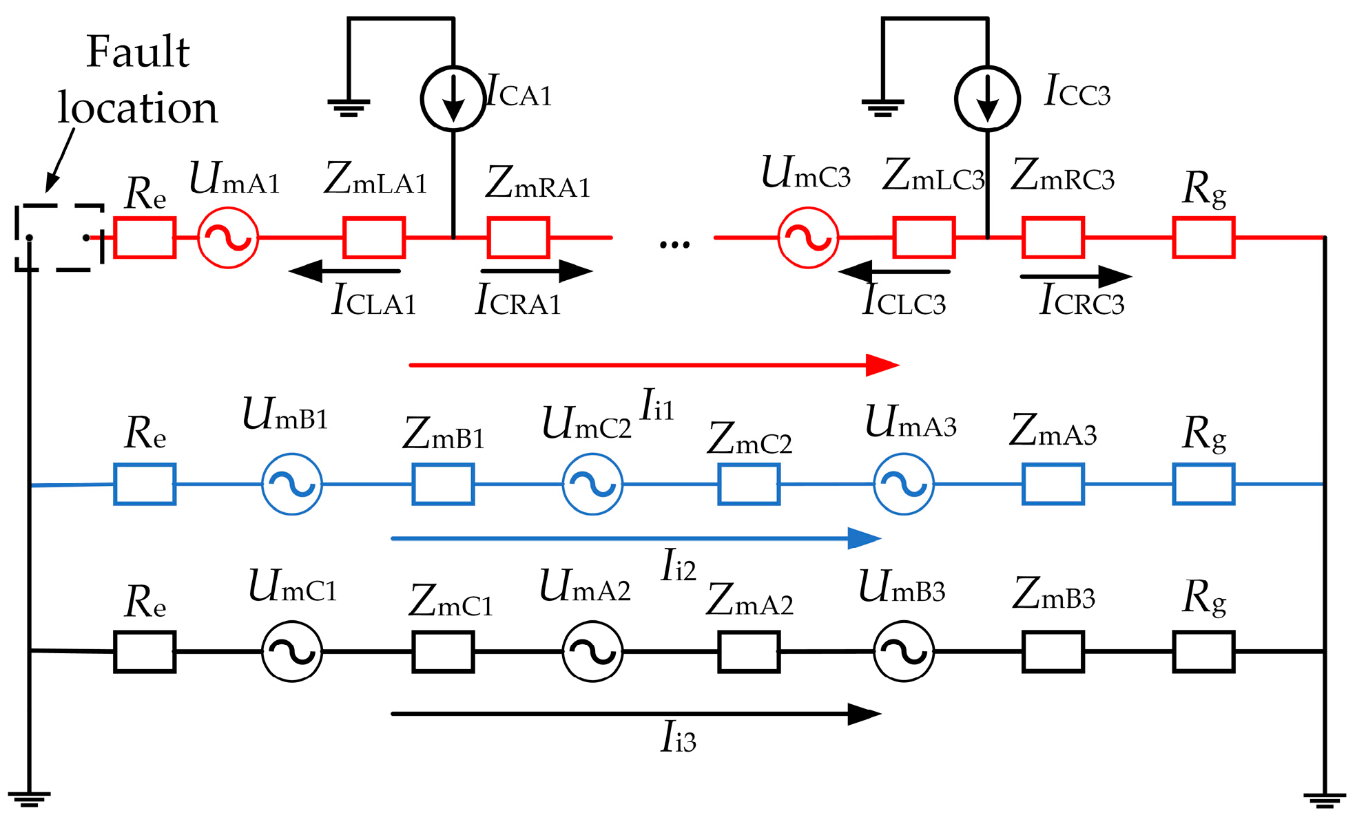
3. Analytical Calculations of Sheath Currents under Fault Conditions

In this paper, 17 common grounding system sheath faults are considered, which can more comprehensively contain the operational states of the grounding system. Faults are classified by type as sheath loop open circuit, the breakdown of cable joint, the flooding in link box, and the sheath grounding fault, as shown in Table 2.

3.1. Sheath Loops Open Circuit Fault

An open circuit fault occurs in the sheath loops, and the metal sheath is not effectively grounded and cannot form a closed loop. The causes of sheath loop open circuit faults include loose cable joints, improper installation, or third-party Sabotage [15]. Take the example of an open circuit fault at the first end of the sheath loop L1, as shown in Figure 5 (the leakage currents of the sheath loops L2 and L3 are not marked in the figure).
The value of Ii1 is zero when an open circuit fault occurs in the sheath loop L1, but there is also a leakage current component in the sheath loop, and the sheath current of the grounding box is shown in Equation (14).
I sa 1 = 0 I sa 2 = I i 2 ( I CRB 1 + I CRC 2 + I CRA 3 ) + ( I CLB 1 + I CLC 2 + I CLA 3 ) I sa 3 = I i 3 ( I CRC 1 + I CRA 2 + I CRB 3 ) + ( I CLC 1 + I CLA 2 + I CLB 3 ) I sa 4 = I i 2 + ( I CRB 1 + I CRC 2 + I CRA 3 ) ( I CLB 1 + I CLC 2 + I CLA 3 ) I sa 5 = I i 3 + ( I CRC 1 + I CRA 2 + I CRB 3 ) ( I CLC 1 + I CLA 2 + I CLB 3 ) I sa 6 = I CA 1 + I CB 2 + I CC 3

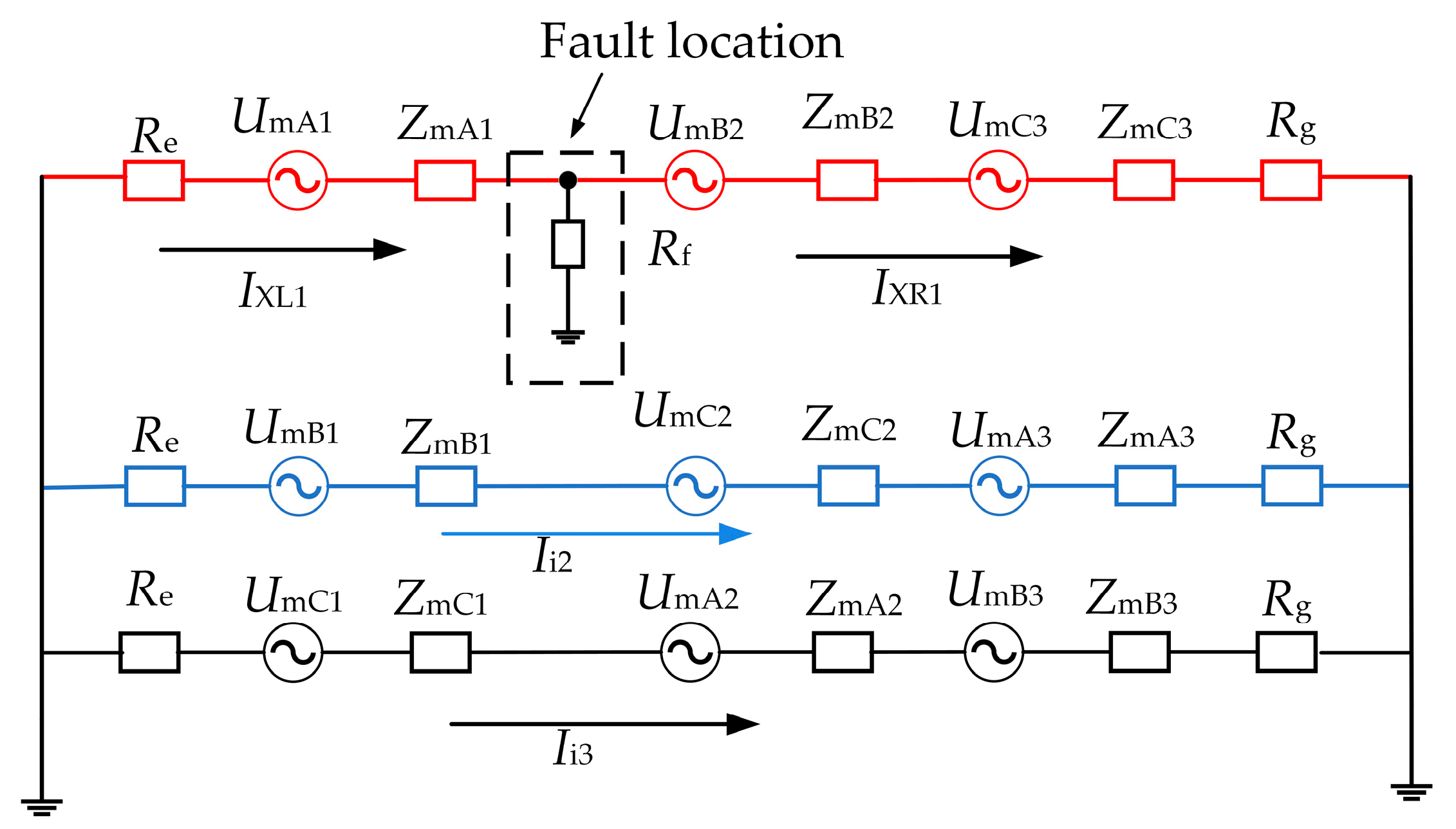
3.2. Cable Joint Breakdown Fault

Cable joints are one of the high incidence parts of cable faults, and cable joint breakdown faults may be triggered when the grounding system generates overvoltage or suffers lightning strikes, or when the production process and construction environment cause burrs or impurities in the insulation part inside the cable joint [16,17]. The insulation plate of the cable joint is broken through, resulting in shorting of the metal sheath at the left and right ends of the joint, destroying the cross-bonded system, while the sheath current rises rapidly, affecting the safe operation of the whole cable. In the case of a breakdown fault in cable joint JA1, for example, the A1 minor section of sheath loop L1 and the A2 minor section of sheath loop L3 are sent short, and the equivalent circuit diagram is shown in Figure 6 (the sheath induced current in sheath loop L2 is not affected by the breakdown fault in cable joint JA1 and is not drawn in the diagram to simplify the circuit).
In Figure 6, IXLn and IXRn (n = 1, 3) are the sheath induced currents on the left and right sides of the nth loop fault point, and Rf is the fault resistance. According to the mesh current method, the mesh currents If1, If2, and If3 can be calculated from Equation (15).
U mA 1 U mC 1 = I f 1 ( 2 R e + Z mA 1 + Z mC 1 ) I f 2 R f I f 3 ( R e + Z mC 1 ) U mB 2 + U mC 3 U mA 2 U mB 3 = I f 1 R f I f 3 ( R g + Z mA 2 + Z mB 3 ) + I f 2 ( 2 R g + Z mB 2 + Z mC 3 + Z mA 2 + Z mB 3 ) U mC 1 + U mA 2 + U mB 3 = I f 3 ( R e + Z mC 1 + Z mA 2 + Z mB 3 + R g ) I f 1 ( R e + Z mC 1 ) I f 2 ( R g + Z mA 2 + Z mB 3 )
The sheath induced currents flowing in the sheath loops L1 and L3 are shown in Equation (16).
I XL 1 = I f 1 I XR 1 = I f 2 I XL 3 = I f 3 I f 1 I XR 3 = I f 3 I f 2
Therefore, when a breakdown fault occurs in cable joint JA1, the sheath current in the grounding box is as shown in Equation (17).
I sa 1 = I CL 1 I XL 1 I CR 1 I sa 2 = I i 2 ( I CRB 1 + I CRC 2 + I CRA 3 ) + ( I CLB 1 + I CLC 2 + I CLA 3 ) I sa 3 = I CL 3 I XL 3 I CR 3 I sa 4 = I i 2 + ( I CRB 1 + I CRC 2 + I CRA 3 ) ( I CLB 1 + I CLC 2 + I CLA 3 ) I sa 5 = I XR 3 + I CR 3 I CL 3 I sa 6 = I XR 1 + I CR 1 I CL 1
where ICLn and ICRn (n = 1, 3) represent the leakage current components flowing into the left and right ends of the nth sheath loop.

3.3. Flooding in Link Box

In some areas of China, a large amount of standing water will soak into the cable tunnels during the rainy season every year, and when the link box is damaged or poorly sealed, it causes the protector inside the whole box to be flooded and the sheath is directly connected to the earth, which seriously affects the safe operation of the whole system [18]. Taking the flooding in link box J1 fault as an example, the equivalent circuit diagram is shown in Figure 7 (the leakage current components are not marked in the diagram). IXLn and IXRn (n = 1, 2, 3) represent the sheath induced currents on the left and right sides of the nth loop fault point. As the resistance formed by the water inside the box is small, the water body inside and outside the box is connected, and in general, the area of the water body is much larger than its depth, therefore, the water resistance is negligible [19].
When flooding in link box J1 fault occurs, the sheath circuit is changed, then the capacitive current component flowing into the ends of the sheath is also changed, to A1 minor section as an example, the capacitive current component is calculated as shown in the Equation (18).
I CLA 1 = Z mRA 1 Z mLA 1 + Z mRA 1 + R e I CA 1 I CRA 1 = Z mLA 1 + R e Z mLA 1 + Z mRA 1 + R e I CA 1
According to the equivalent circuit of Figure 7, the sheath induced current is calculated as shown in Equation (19).
I XL 1 = U mA 1 Z mA 1 + R e   ,   I XR 1 = U mB 2 + U mC 3 Z mB 2 + Z mC 3 + R g I XL 2 = U mB 1 Z mB 1 + R e   ,   I XR 2 = U mC 2 + U mA 3 Z mC 2 + Z mA 3 + R g   I XL 3 = U mC 1 Z mC 1 + R e   ,   I XR 3 = U mA 2 + U mB 3 Z mA 2 + Z mB 3 + R g
Therefore, the first end of the grounding box sheath current as shown in Equation (20).
I sa 1 = I CLA 1 I XL 1 I sa 2 = I CLB 1 I XL 2 I sa 3 = I CLB 1 I XL 3 I sa 4 = I XR 2 + ( I CRC 2 + I CRA 3 ) ( I CLC 2 + I CLA 3 ) I sa 5 = I XR 3 + ( I CRA 2 + I CRB 3 ) ( I CLA 2 + I CLB 3 ) I sa 6 = I XR 1 + ( I CRB 2 + I CRC 3 ) ( I CLB 2 + I CLC 3 )

3.4. Sheath Grounding Fault

In the actual operation of the cable, overvoltage caused by various reasons can cause the breakdown of the protector in the link box and trigger a sheath grounding fault. In addition, natural factors such as environmental humidity, soil acid and alkali corrosion, as well as external causes such as termites and rats gnawing lead to outer sheath breakage, which can also cause sheath grounding faults. Take the example of a sheath ground fault occurring at cable joint JA1, the equivalent circuit diagram is shown in Figure 8.
Cable joint JA1 occurs sheath ground fault, the capacitive current component flowing into both ends of the sheath also changes, taking A1 minor section as an example, the capacitive current component is calculated as shown in Equation (21).
I CLA 1 = Z mRA 1 + R f Z mLA 1 + Z mRA 1 + R e + R f I CA 1 I CRA 1 = Z mLA 1 + R e Z mLA 1 + Z mRA 1 + R e + R f I CA 1
According to Figure 8, the sheath loop L1 sheath induced current is calculated as shown in Equation (22).
I XL 1 = U mA 1 Z mA 1 + R e + R f I XR 1 = U mB 2 + U mC 3 Z mB 2 + Z mC 3 + R g + R f
Therefore, when a sheath ground fault occurs at cable joint JA1, the sheath current of the first end direct grounding box is shown in Equation (23).
I sa 1 = I CLA 1 I XL 1 I sa 2 = I i 2 ( I CRB 1 + I CRC 2 + I CRA 3 ) + ( I CLB 1 + I CLC 2 + I CLA 3 ) I sa 3 = I i 3 ( I CRC 1 + I CRA 2 + I CRB 3 ) + ( I CLC 1 + I CLA 2 + I CLB 3 ) I sa 4 = I i 2 + ( I CRB 1 + I CRC 2 + I CRA 3 ) ( I CLB 1 + I CLC 2 + I CLA 3 ) I sa 5 = I i 3 + ( I CRC 1 + I CRA 2 + I CRB 3 ) ( I CLC 1 + I CLA 2 + I CLB 3 ) I sa 6 = I XR 1 + ( I CRB 2 + I CRC 3 ) ( I CLB 2 + I CLC 3 )

3.5. Constructing Feature Vectors

The sheath current of an HV cable grounding system contains both amplitude and phase information, and different types of faults can produce different sheath currents. Therefore, this paper detects and diagnoses different fault types by the magnitude and phase of the sheath currents flowing into the first and last ends of the grounding box. In order to make the constructed feature vectors can reflect the sheath current characteristics of the same loop, but also can weaken the influence of load current, minor section length, phase distance, and other factors on the sheath current, therefore, the sheath current amplitude ratio and phase difference of the same loop and the same grounding box is constructed as feature vectors, which can reflect the different operating conditions of the HV cable sheath loop. The corresponding magnitude and phase of the sheath currents flowing into the first and last grounding boxes are shown in Equation (24).
I ˙ sa 1 = I 1 φ 1 ,   I ˙ sa 2 = I 2 φ 2 ,   I ˙ sa 3 = I 3 φ 3   I ˙ sa 4 = I 4 φ 4 ,   I ˙ sa 5 = I 5 φ 5 ,   I ˙ sa 6 = I 6 φ 6
where In and φn (n = 1, 2, 3, 4, 5, 6) are the amplitude and phase angle of the sheath current I ˙ san .
The amplitude ratio and phase difference of the same grounding box sheath current is shown in Equation (25).
a 1 b 1 = I ˙ sa 2 I ˙ sa 1 = I 2 φ 2 I 1 φ 1 a 2 b 2 = I ˙ sa 3 I ˙ sa 1 = I 3 φ 3 I 1 φ 1 a 3 b 3 = I ˙ sa 5 I ˙ sa 4 = I 5 φ 5 I 4 φ 4 a 4 b 4 = I ˙ sa 6 I ˙ sa 4 = I 6 φ 6 I 4 φ 4
The amplitude ratio and phase difference of the sheath currents at the first and last ends of the same circuit are shown in Equation (26).
a 5 b 5 = I ˙ sa 6 I ˙ sa 1 = I 6 φ 6 I 1 φ 1 a 6 b 6 = I ˙ sa 4 I ˙ sa 2 = I 4 φ 4 I 2 φ 2 a 7 b 7 = I ˙ sa 5 I ˙ sa 3 = I 5 φ 5 I 3 φ 3
In view of the above, the 14 feature vectors [a1, a2, a3, a4, a5, a6, a7, b1, b2, b3, b4, b5, b6, b7] are constructed to comprehensively reflect the operation states of the cable grounding system.

4. Build Fault Database

According to the data provided by a power company, the cable with a voltage level of 110 kV was selected for simulation by PSCAD software. The schematic diagram of the power system is shown in Figure 9, the length of the main section of the cable is 1500 m, the length of each minor section is 500 m, and the cross-sectional area of the cable core is 800 mm2.
The specific cable structure parameters are shown in Table 3. The three-phase cable is laid horizontally, as shown in Figure 10, with a direct burial depth of 1 m and a distance of 0.35 m between the two phases.
Simulation of different fault types by changing the fault time, grounding resistance, cable laying spacing, and cable minor section length were carried out to construct a database of 14 feature vectors containing 18 grounding system operating states, as shown in Table 4. In Table 4, the first column represents the 18 fault categories and first row represents the 14 feature vectors which are a1, a2, a3, a4, a5, a6, a7, b1, b2, b3, b4, b5, b6, b7. The database contains a total of 35,910 groups of data, among which, 3780 groups of normal operation state and 1890 groups of each of 17 types of faults.

5. Fault Diagnosis

In recent years, with the wide application of data mining technology, data classification algorithms have emerged and gradually optimized, among which the traditional machine learning classification algorithms are Decision tree (DT), Naive bayes classification (NBC), Support vector machines (SVM), Discriminant analysis (DA), K-nearest neighbor (KNN), etc. [20,21,22]. These algorithms are mostly applicable to the processing of samples with small data volume. For samples with large amounts of data, deep learning can better mine the potential features of the data. In this paper, an LSTM neural network is chosen, which is improved based on Recurrent neural networks (RNN) and is widely used for time series of samples due to its characteristics and is important for applications such as electricity load forecast, bearing Fault Diagnosis, and power quality classification [23,24,25]. The LSTM algorithm has an advantage over other algorithms in handling sequential data and can solve the gradient disappearance or explosion problem of other algorithms, which can be extended to the application of intelligent diagnosis of faults in HV cable grounding systems in conjunction with practical situations.
The flow chart of cable grounding system fault diagnosis based on LSTM in this paper is shown in Figure 11.
The fault diagnosis process of cable grounding systems based on LSTM is divided into the following stages:
(a)
Data acquisition stage. This paper establishes an HV cable grounding system model through PSCAD software simulation and acquires the amplitude and phase angle signals of the first and last sheath currents of the cable for one cycle (system frequency is 50 Hz, acquisition frequency is 1000 Hz) under 17 fault operation states and normal operation states.
(b)
Data pre-processing stage. The fault database with 14 feature vectors according to Equations (25) and (26) is normalized. The processed database is divided into test and training sets by 4:1 according to the cross-validation method.
(c)
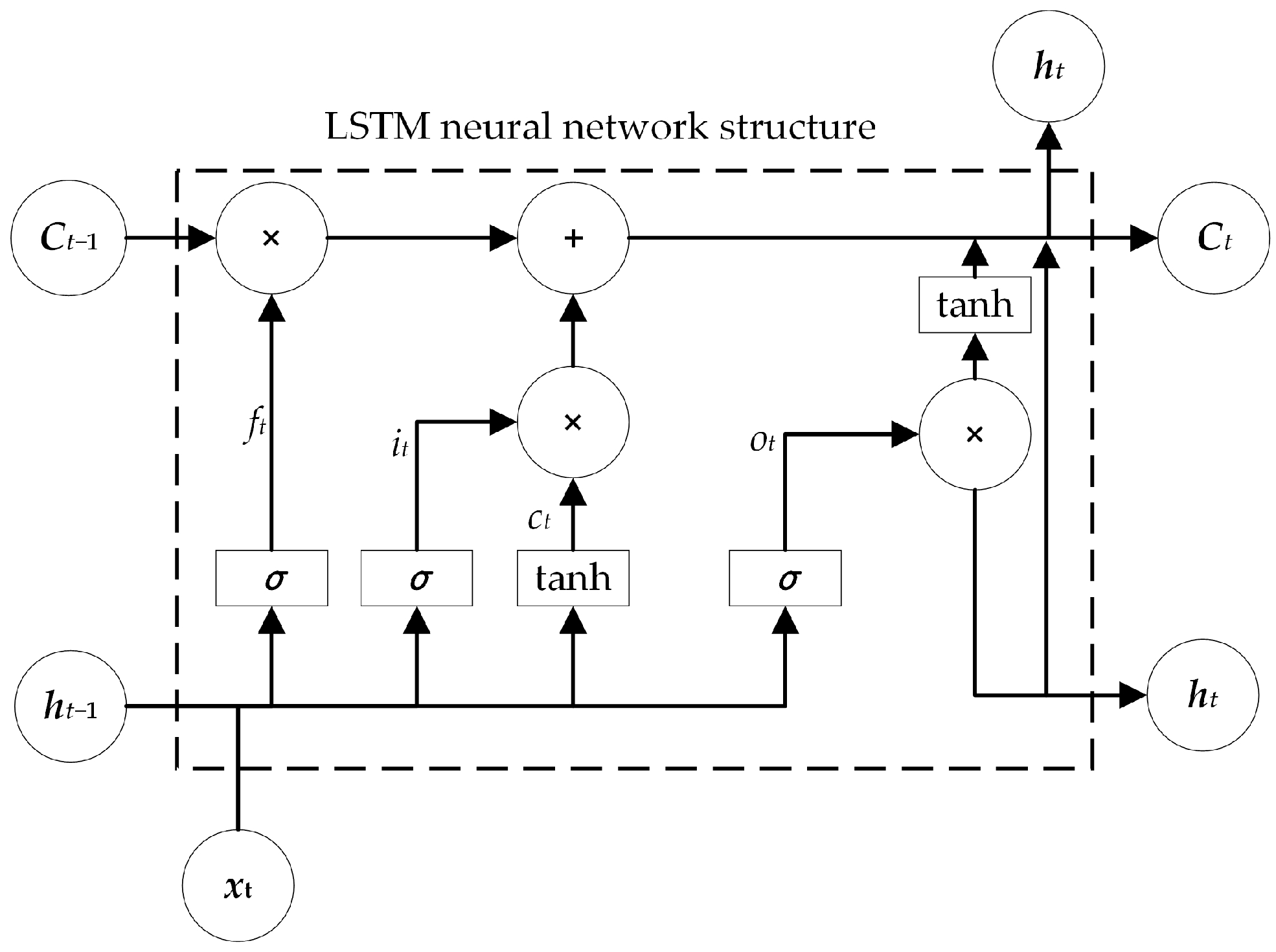
Model training stage. The model diagnosis framework based on LSTM is shown in Figure 12. The model of the LSTM is divided into the input layer, the LSTM layer, the fully connected layer, the softmax layer, and the output layer. The three gate structures, the forgetting gate, the input gate, and the output gate, form the basic unit of the LSTM and the structure is shown in Figure 13. The LSTM model is trained using the training set, and when the model training accuracy reaches 99%, the model is saved.
The relevant calculation is shown in Equation (27).
f t = σ W f h t 1 , x t + b f i t = σ W i h t 1 , x t + b i c ˜ t = tanh W c h t 1 , x t + b c c t = f t c t 1 + i t c ˜ t o t = σ W o h t 1 , x t + b o h t = o t tanh c t
where xt is the input value, ht is the hidden layer state, and ct indicates memory cells. Wf, Wi, Wc, and Wo are the corresponding weights for each gate in each cell, and bf, bi, bc, and bo are the corresponding biases.
(d)
Model application stage. The test set is input to the training saved model for fault diagnosis identification.
The implicit units of the LSTM were set to 100, the output nodes were 18, the learning rate was set to 0.001, the maximum number of training rounds was 100, and the GPU was selected as the execution environment of the network. The training accuracy and loss values of the long and short-term memory neural network algorithm are shown in Figure 14. The confusion matrix of the classification results of the different algorithms are shown in Figure 15.
As shown in Figure 14, the test set has a total of 7182 data identified with 100% accuracy. Comparing the diagnosis results of DT, DA, NBC, KNN, and SVM, as shown in Table 5.
As can be seen from Table 5, the accuracy of DT, DA, NBC, KNN, and SVM are 87.37%, 81.64%, 87.65%, 96.88%, and 97.37%, respectively. Compared with traditional machine learning algorithms, the accuracy of the algorithm proposed in this paper is higher, and the accuracy reaches 100% in 18 operating states, while providing an accurate and effective method for the metal sheath grounding system of HV cables fault diagnosis provides an accurate and effective method.

6. Conclusions

Aiming at the problem of low accuracy and efficiency of existing fault diagnosis methods for HV cable grounding systems, this paper proposes an intelligent fault diagnosis method for HV cable metal sheath grounding system based on LSTM.
(1)
Established an HV cable metal sheath grounding system model, analyzed four types of fault sheath currents, constructed 14 feature vectors with amplitude ratio and phase difference.
(2)
Building a fault database with 18 grounding system operating states by varying fault time, grounding resistance, cable lay spacing, and cable minor section length for different fault types.
(3)
By comparing the simulation results of different algorithms, the identification accuracy of the fault diagnosis of HV cable grounding system based on LSTM is the highest, and its accuracy rate reaches 100%.
(4)
The sheath current samples used for fault diagnosis in high-voltage cable grounding systems are in error with the actual sheath currents and further field verification is required.

Author Contributions

Conceptualization, Q.W. and X.Y.; methodology, X.Y.; software, X.Y.; validation, Q.W. and X.Y.; formal analysis, X.Y.; investigation, Q.W.; data curation, X.Y.; writing—original draft preparation, X.Y.; writing—review and editing, Q.W. All authors have read and agreed to the published version of the manuscript.

Funding

This work was supported by the Fund Project of Beijing Education Commission: Key Technology Research on Intelligent Operation and Maintenance of Big Data for Power Distribution under Grant (110052972027/067); Collaborative Innovation Center of Key Power Energy-Saving Technologies in Beijing under Grant (PXM2018_014212_000015_4_4); Technology project of State Grid Shanxi Electric Power Company: Research and Application of Cable electrification diagnosis Technology based on Harmonic method (5205C02000GL).

Institutional Review Board Statement

Not applicable.

Informed Consent Statement

Not applicable.

Data Availability Statement

Not applicable.

Conflicts of Interest

The authors declare no conflict of interest.

References

  1. Di Sante, R.; Ghaderi, A.; Mingotti, A.; Peretto, L.; Tinarelli, R. Effects of Thermal Cycles on Interfacial Pressure in MV Cable Joints. Sensors 2020, 20, 169. [Google Scholar] [CrossRef] [PubMed]
  2. Wang, Y.W.; Chen, P.; Sun, Y.Y.; Feng, C. A Comprehensive Operation Status Evaluation Method for Mining XLPE Cables. Sensors 2022, 22, 7174. [Google Scholar] [CrossRef] [PubMed]
  3. Gulski, E.; Jongen, R. Condition Based Maintenance of Transmission Power Cables. IEEE Trans. Power Deliv. 2022, 37, 1588–1597. [Google Scholar] [CrossRef]
  4. Su, J.G.; Wei, L.Q.; Zheng, J.Q.; Liu, J.H.; Zhang, P.; Pang, X.H.; Xing, Y.Q. Effects of Mechanical Stress on Insulation Structure and Performance of HV Cable. Polymers 2022, 14, 2927. [Google Scholar] [CrossRef]
  5. Zhu, B.; Yu, X.; Tian, L.; Wei, X. Insulation Monitoring and Diagnosis of Faults in Cross-Bonded Cables Based on the Resistive Current and Sheath Current. IEEE Access 2022, 10, 46057–46066. [Google Scholar] [CrossRef]
  6. GB 50217-2007; Code for Design of Cables of Electric Engineering. China Planning Press: Beijing, China, 2007.
  7. Li, Z.L.; Du, B.X.; Li, W. Evaluation of high-voltage AC cable grounding systems based on the real-time monitoring and theoretical calculation of grounding currents. High Volt. 2018, 3, 38–43. [Google Scholar] [CrossRef]
  8. Wu, L.; Wouters, P.; Steennis, F.E. Frequency-domain transient analysis in double-circuit mixed HV overhead line-cable connection including cross-bonding. Int. Trans. Electr. Energy Syst. 2016, 26, 1408–1426. [Google Scholar] [CrossRef]
  9. Q/GDW 11316-2014; Test Code for Power Cables. China Electric Power Press: Beijing, China, 2014.
  10. Yuan, Y.; Zhou, H. Sheath Current in HV Cable Systems and Its On-line Monitoring for Cable Fault Diagnosis. High Volt. Eng. 2015, 41, 1194–1203. [Google Scholar]
  11. Du, B.; Li, Z. Calculation and Application of 220 kV Crosslinked Polyethylene power cable Grounding Current. High Volt. Eng. 2013, 39, 1034–1039. [Google Scholar]
  12. Marzinotto, M.; Mazzanti, G. The Feasibility of Cable Sheath Fault Detection by Monitoring Sheath-to-Ground Currents at the Ends of Cross-Bonding Sections. IEEE Trans. Ind. Appl. 2015, 51, 5376–5384. [Google Scholar] [CrossRef]
  13. Zhao, W.; Xia, X.; Liu, Y.; Li, M.; Wang, K. Research on Online Monitoring for HV Cable Running Locus. Proc. CSU-EPSA 2019, 31, 137–143. [Google Scholar]
  14. Zhou, W.; Yang, Y.; Wei, L.; Zhou, C.K. Separation Method of Leakage Current in Cross-bonded Cables and Its Application in On-line Monitoring Relative Change of Dielectric Loss between Phases. High Volt. Eng. 2016, 42, 468–477. [Google Scholar]
  15. Dong, X.; Yang, Y.; Zhou, C.; Hepburn, D.M. Online Monitoring and Diagnosis of HV Cable Faults by Sheath System Currents. IEEE Trans. Power Deliv. 2017, 32, 2281–2290. [Google Scholar] [CrossRef]
  16. Zhang, Z.P.; Zheng, C.J.; Zheng, M.; Zhao, H.; Zhao, J.K.; Sun, W.F.; Chen, J.Q. Interface Damages of Electrical Insulation in Factory Joints of High Voltage Submarine Cables. Energies 2020, 13, 3892. [Google Scholar] [CrossRef]
  17. Ngarmchuen, B.; Kongjeen, Y.; Plangklang, B.; Jitjing, P. In The Effect of Electric Field from the Cable Joint to the Breakdown of Insulation in 24 kV Underground Cables. In Proceedings of the 2021 9th International Electrical Engineering Congress (IEECON), Pattaya, Thailand, 10–12 March 2021; pp. 45–48. [Google Scholar]
  18. Shokry, M.A.; Khamlichi, A.; Garnacho, F.; Malo, J.M.; Alvarez, F. Detection and Localization of Defects in Cable Sheath of Cross-Bonding Configuration by Sheath Currents. IEEE Trans. Power Deliv. 2019, 34, 1401–1411. [Google Scholar] [CrossRef]
  19. Mathiazhagan, M.; Selvakumar, T.; Ganesan, M. Detection of solid waste dumpsite-induced groundwater contamination leachate using electrical resistivity method. In Proceedings of the 6th International Groundwater Symposium, Kuwait Institute for Scientific Research, Safat, Kuwait, 19–21 November 2012; pp. 307–312. [Google Scholar]
  20. Ducange, P.; Fazzolari, M.; Marcelloni, F. An overview of recent distributed algorithms for learning fuzzy models in Big Data classification. J. Big Data 2020, 7, 19. [Google Scholar] [CrossRef]
  21. Lin, W.W.; Wu, Z.M.; Lin, L.X.; Wen, A.Z.; Li, J. An Ensemble Random Forest Algorithm for Insurance Big Data Analysis. IEEE Access 2017, 5, 16568–16575. [Google Scholar] [CrossRef]
  22. Mahdi, M.A.; Hosny, K.M.; Elhenawy, I. Scalable Clustering Algorithms for Big Data: A Review. IEEE Access 2021, 9, 80015–80027. [Google Scholar] [CrossRef]
  23. Lai, C.Q.; Ibrahim, H.; Abd Hamid, A.I.; Abdullah, J.M. Classification of Non-Severe Traumatic Brain Injury from Resting-State EEG Signal Using LSTM Network with ECOC-SVM. Sensors 2020, 20, 5234. [Google Scholar] [CrossRef]
  24. Qiao, M.Y.; Yan, S.H.; Tang, X.X.; Xu, C.K. Deep Convolutional and LSTM Recurrent Neural Networks for Rolling Bearing Fault Diagnosis under Strong Noises and Variable Loads. IEEE Access 2020, 8, 66257–66269. [Google Scholar] [CrossRef]
  25. Suebsombut, P.; Sekhari, A.; Sureephong, P.; Belhi, A.; Bouras, A. Field Data Forecasting Using LSTM and Bi-LSTM Approaches. Appl. Sci. Basel 2021, 11, 11820. [Google Scholar] [CrossRef]
Figure 1. HV cable grounding system model.
Applsci 13 02453 g001
Figure 2. Schematic diagram of sheath current loops.
Applsci 13 02453 g002
Figure 3. The A1 minor section cable equivalent two-port network.
Applsci 13 02453 g003
Figure 4. Equivalent induction circuit of metal sheath of cross-bonded cable.
Applsci 13 02453 g004
Figure 5. Equivalent circuit diagram of sheath loop L1 open circuit fault.
Applsci 13 02453 g005
Figure 6. Equivalent circuit diagram of breakdown fault of cable joint JA1.
Applsci 13 02453 g006
Figure 7. Equivalent circuit diagram of flooding in link box J1 fault.
Applsci 13 02453 g007
Figure 8. Equivalent circuit diagram of grounding fault of cable joint JA1.
Applsci 13 02453 g008
Figure 9. Schematic diagram of a power system with a cross-connected main section.
Applsci 13 02453 g009
Figure 10. Schematic diagram of horizontal laying of three-phase cable.
Applsci 13 02453 g010
Figure 11. Flow chart of cable grounding system fault diagnosis based on LSTM.
Applsci 13 02453 g011
Figure 12. LSTM model diagnostic framework diagram.
Applsci 13 02453 g012
Figure 13. Basic unit structure of LSTM.
Applsci 13 02453 g013
Figure 14. Training loss value and accuracy of LSTM algorithm.
Applsci 13 02453 g014
Figure 15. Confusion matrix of classification results of different algorithms. (a) DT algorithm; (b) DA algorithm; (c) NBC algorithm; (d) KNN algorithm; (e) SVM algorithm; (f) LSTM algorithm.
Applsci 13 02453 g015aApplsci 13 02453 g015b
Table 1. Comparison of existing diagnostic methods.
LiteratureFull Range of Fault TypesSimple Measuring EquipmentSimple ModelsHigh Accuracy
SGCC corporate standard [9]
Yuan et al. [10]
Du et al. [11]
Zhao W al. [13]
Proposed
Table 2. HV cable grounding system sheath fault classification.
Fault TypeOperation States TypeSerial Number
Normal/0
Sheath loop open circuitSheath loop L1 open circuit1
Sheath loop L2 open circuit2
Sheath loop L3 open circuit3
Breakdown of cable jointBreakdown of joint JA14
Breakdown of joint JB15
Breakdown of joint JC16
Breakdown of joint JA27
Breakdown of joint JB28
Breakdown of joint JC29
Flooding in link boxFlooding in link box J110
Flooding in link box J211
Sheath groundingJoint JA1 sheath grounding12
Joint JB1 sheath grounding13
Joint JC1 sheath grounding14
Joint JA2 sheath grounding15
Joint JB2 sheath grounding16
Joint JC2 sheath grounding17
Table 3. Structural parameters of the cable.
ParametersValue
The outside diameter of cable core/mm34
The outside diameter of insulation layer/mm68.8
The inner diameter of metal sheath/mm78.8
The outside diameter of metal sheath/mm98.8
Sheath temperature coefficient)4.03
The relative dielectric constant of main insulation2.3
Metal sheath resistivity coefficient/(nΩ·m−1)28.4
Cable core resistivity coefficient/(nΩ·m−1)16.8
Length of a minor section of cable/m500
Grounding resistance/Ω1
System frequency/Hz50
Table 4. HV cable grounding system fault database.
Fault Numbera1a2b7
01.2381.104−0.02
01.2451.130−0.02
125.48119.564−0.03
125.92520.493−0.03
170.7540.877−2.39
170.8150.876 −2.39
Table 5. Accuracy of different algorithms.
NumberDTDANBCKNNSVMLSTM
098.49%96.86%81.79%98.45%99.08%100%
198.06%86.06%100%99.73%100%100%
296.21%73.13%100%99.74%100%100%
399.46%84.84%99.45%98.96%100%100%
463.92%61.39%97.38%97.53%99.76%100%
593.62%98.37%97.14%99.47%95.85%100%
697.84%82.10%80.81%98.30%98.14%100%
779.44%84.52%91.38%100%99.48%100%
899.14%97.47%98.28%95.84%97.59%100%
987.53%21.26%43.40%96.88%97.72%100%
1093.77%80.42%95.80%96.07%99.74%100%
1195.82%89.55%90.74%96.64%94.40%100%
1288.75%74.95%92.82%95.92%93.99%100%
1398.70%93.83%88.34%96.87%98.13%100%
1482.16%77.57%52.12%87.23%87.12%100%
1598.72%87.65%91.56%96.61%96.24%100%
1695.04%94.89%93.47%93.88%96.73%100%
170%68.78%89.70%96.40%95.49%100%
Accuracy87.37%81.64%87.65%96.88%97.31%100%
Disclaimer/Publisher’s Note: The statements, opinions and data contained in all publications are solely those of the individual author(s) and contributor(s) and not of MDPI and/or the editor(s). MDPI and/or the editor(s) disclaim responsibility for any injury to people or property resulting from any ideas, methods, instructions or products referred to in the content.

