Article

Seismic Performance of Fully Prefabricated L-Shaped Shear Walls with Grouted Sleeve Lapping Connectors under High Axial Compression Ratio

1
Department of Disaster Mitigation for Structures, Tongji University, Shanghai 200092, China
2
Shanxi Construction Engineering Group Co., Ltd., Taiyuan 030006, China
3
Shanxi Erjian Group Co., Ltd., Taiyuan 030013, China
*
Author to whom correspondence should be addressed.
Appl. Sci. 2023, 13(4), 2301; https://doi.org/10.3390/app13042301
Submission received: 1 January 2023 / Revised: 4 February 2023 / Accepted: 6 February 2023 / Published: 10 February 2023
(This article belongs to the Section Civil Engineering)

Abstract

:

Featured Application

The grouted sleeve lapping connector in this work has the advantages of low cost and ease of construction, and it can realize full prefabrication of vertical components. In this paper, pseudo-static tests of L-shaped shear walls with high axial compression ratio are carried out to investigate the connection reliability of the joint under seismic action.

Abstract

The grouted sleeve lapping connector called the APC connector has the advantages of high fault tolerance, convenient construction, compacted grouting, and low cost, together with realizing full prefabrication of vertical components. In this paper, a quasi-static test of two fully prefabricated L-shaped walls connected with two types of APC connector and a cast-in-place wall was carried out under high axial compression ratio (0.5) to compare their seismic performance. The results indicated that the two types of connectors effectively transferred the rebar stress in the prefabricated walls, and the failure modes and final crack distribution of the prefabricated walls and the cast-in-place wall were basically identical. The failure of the cast-in-place wall occurred at the root of the wall limb, while the failure of the prefabricated walls occurred at the top of the sleeve due to the constraint of the sleeve. The bearing capacity, stiffness, ductility, and energy dissipation of the prefabricated specimen connected by the type-I sleeve was comparable to that of the cast-in-place wall, while the prefabricated wall connected by the type-II sleeve showed greater bearing capacity, stiffness, and ductility. Finally, some suggestions for seismic design of prefabricated components connected with APC connectors are proposed.

1. Introduction

Compared with traditional cast-in-place structures, prefabricated structures have been increasingly used due to their environmental friendliness, low cost, and fast construction speed with the rapid development of building industrialization [1]. At present, the sleeve grouting connection is the most widely used rebar-splicing technology, since it can achieve a reliable connection between prefabricated components [2]. As shown in Figure 1a, two rebars located in a line are placed in the center of the sleeve and connected by non-shrinkage grouting material to form a whole. Since Yee [3] invented the grouting sleeve technology for splicing rebars, researchers have carried out extensive experimental studies on the performance of grouted splice connectors under uniaxial tension and cyclic loads [4,5,6,7,8]. The effects of different load conditions and research parameters, such as rebar diameter, sleeve dimension, anchoring length, and grouting defects, etc., on the mechanical properties of the connectors were evaluated, and the results showed that the grouted splice connectors with reasonable design parameters met the requirements of strength, stiffness, and ductility.
In order to study the reliability of grouted splice connectors in components, the seismic performance of prefabricated columns and walls connected by grouted splice connectors has been extensively investigated [9,10,11,12,13,14,15,16,17,18], and the results showed that the prefabricated components connected with grouted splice connectors had reliable seismic performance. Furthermore, some recommendations for seismic design of prefabricated components were put forward. However, to ensure the bearing capacity of the connector, the inner diameter of the sleeve is usually small, which undoubtedly causes an increase in the difficulty of construction. Further, it is difficult to ensure the alignment of the rebars during construction, which will lead to the occurrence of grouting defects [8,18]. Since the two rebars are discontinuous in the sleeve, the section in the middle of the sleeve is the weak part under stress. Therefore, a complicated process and more expense are required to properly treat the inner wall of the sleeve.
Based on the above situation, Yu [19] proposed a new type of grouted sleeve lapping connector, referred to as APC (all vertical members precast in concrete structures) connector. APC connectors are divided into two types, among which the type-I connector is composed of two overlapping rebars, grouting material, and a sleeve, as shown in Figure 1b, and the type-II connector shown in Figure 1c consists of four overlapping rebars, grouting material, and a sleeve. Due to the opposite direction of the force on the lapped rebars in the sleeve, the forces on the sleeve (grouting material) cancel each other out. Therefore, the APC connector has lower requirements on the performance of the sleeve and the grouting material, that is, the inner wall of the sleeve does not need special treatment, and the grouting material grade can be C60 instead of the traditional grouting material C80. Moreover, the inner diameter of the type-I sleeve is generally 25 mm to 30 mm larger than the diameter of the rebar. The larger gap makes the maximum aggregate particle size of the grouting material up to 4.75 mm. As a result, compared with the traditional grouted splice connector, the APC connector has the advantages of large fault tolerance, convenient construction, easy and compact grouting, and low cost.
In order to explore the mechanical properties of APC connectors, Yu et al. [20,21,22,23] conducted uniaxial tensile tests of type-I and type-II connectors, and studied the failure mode, ultimate bearing capacity, force-displacement curve, and sleeve strain. It was recommended that the lap length of the type-I connector was 12.5 d, and the lap length of the type-II connector with the diameter of the rebar less than 25 mm was 18 d (where d is the diameter of the rebar). In recent years, studies have shown that the ultimate bearing capacity, ductility, and energy consumption of the straight shear wall and frame column using this splicing method are comparable to those of the corresponding cast-in-place components [24,25]. However, the research on its application performance in actual structural components is still insufficient.
At present, the research on prefabricated walls mainly focused on the straight shear walls [10,14,15,16,17,18]. However, in order to meet the requirements of building functions, L-shaped shear walls are often used in practical projects. Due to the asymmetric geometry of L-shaped shear walls, the wall body is susceptible to eccentric lateral force. It is apparent that L-shaped shear walls have higher requirements for joint connections. Therefore, the reliability of L-shaped shear walls connected by APC connectors urgently needs to be evaluated. Besides, previous studies have focused on the effects of low axial compression, i.e., axial compression ratio less than 0.3, on the seismic performance of prefabricated components [10,14,16,25,26]. In practical projects, both large structural dead weight and insufficient concrete strength will cause large axial compression ratio, which is a great challenge to the seismic performance of the structure. Furthermore, with the increase of axial compression ratio, the ductility and energy dissipation of the specimen decreased obviously [15,27]. Therefore, it is necessary to investigate whether the prefabricated specimen can achieve the seismic performance equivalent to the cast-in-place specimen under high axial compression ratio [26]. According to reference [26], the axial compression ratio of 0.5 was selected for this test.
To study the seismic performance of a fully prefabricated L-shaped shear wall connected by an APC connector under high axial compression ratio, three full-scale L-shaped shear walls, including a cast-in-place wall and two prefabricated walls, one connected by a type-I connector and the other by a type-II APC connector, were designed for a quasi-static test, and the failure modes, bearing capacity, stiffness, deformation, and energy dissipation of the specimens under the axial compression ratio of 0.5 were comparatively studied.

2. Experimental Program

2.1. Specimens Design

2.1.1. Shear Wall

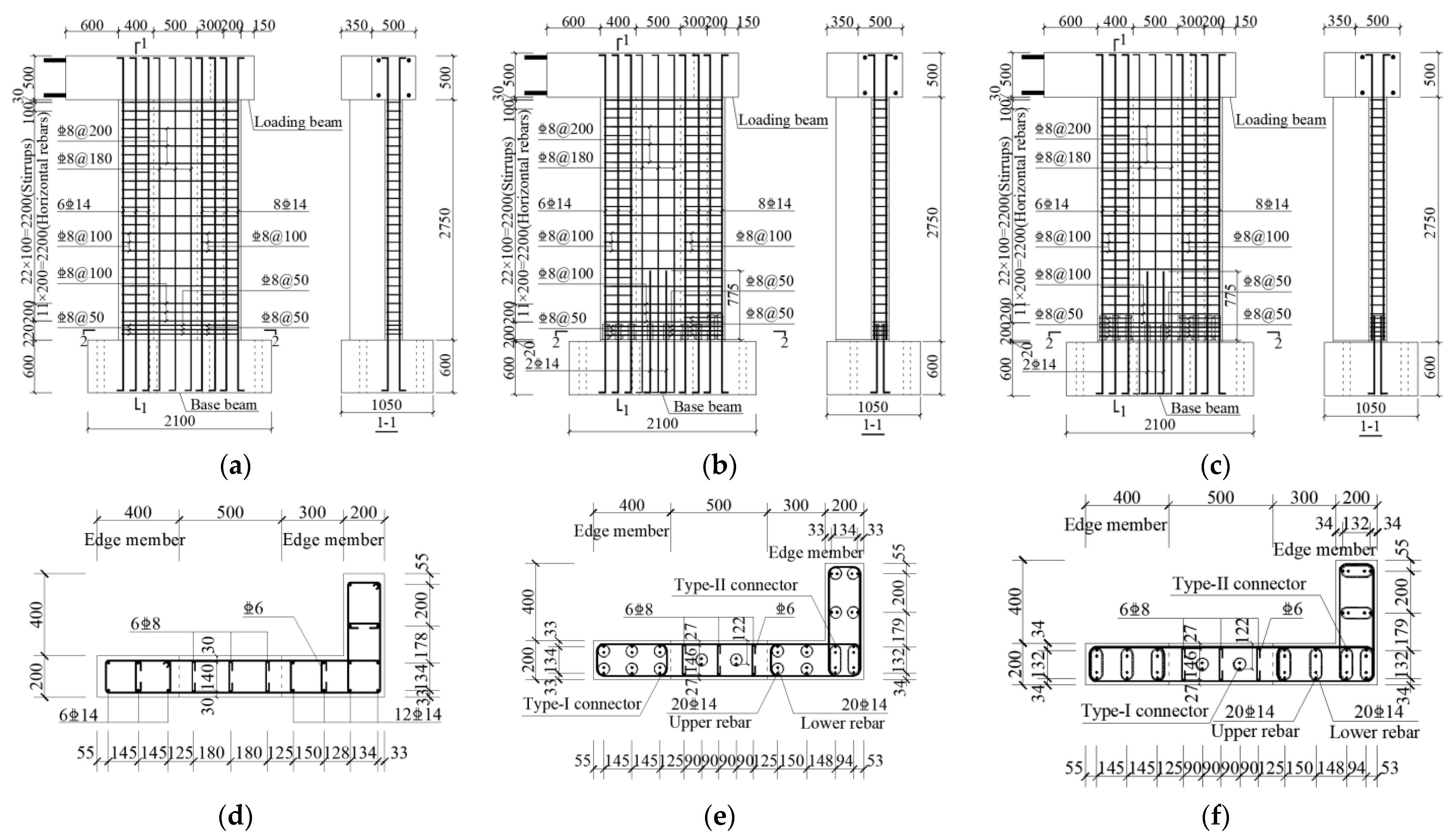
In this experiment, a quasi-static test of two fully prefabricated walls connected with two types of APC connectors and a cast-in-place wall has been carried out, and the seismic performance of the two prefabricated specimens was compared with that of the cast-in-place specimen. The cross-sectional dimensions and reinforcement of each specimen are shown in Figure 2. A total of three L-shaped short-leg shear walls were designed, of which LSW was a cast-in-place wall, and LAPC-1 and LAPC-2 were prefabricated walls spliced through type-I and type-II connectors, respectively, with the number representing the type of sleeve used. Each specimen was composed of a base beam, shear wall, and load beam with the same dimensions. The shear wall was 200 mm in thickness, 2750 mm in height (a 20 mm thick grouting layer is contained in the prefabricated wall), 1400 mm in straight-edge length, and 600 mm in flange length. The cross-sectional dimensions of the load beam and the base beam were 500 mm × 500 mm and 1050 mm × 600 mm, respectively.
All specimens were equipped with six and twelve longitudinal rebars with a diameter of 14 mm in the straight-edge member and L-shaped-edge member respectively, and stirrups with a diameter of 8 mm and a spacing of 100 mm were also configured. In addition, the vertical distribution bars of the wall were six longitudinal rebars with a diameter of 8 mm and a spacing of 200 mm. The thinnest part of the concrete cover outside the stirrups of the prefabricated wall was 15 mm, which was slightly thinner than the cast-in-place wall.
The difference between the test pieces was mainly reflected in the connection part. As shown in Figure 2b,c, the horizontally distributed rebars of the prefabricated wall were densified within the range from the bottom of the wall to 300 mm higher than the top of the sleeve, i.e., the spacing within the height range of the sleeve was 50 mm and the spacing of the rebars above the sleeve was 100 mm, and the distance from the first horizontally distributed rebar at the upper end of the sleeve to the top of the sleeve was 25 mm [28]. Moreover, in order to prevent premature shedding of the concrete cover outside the sleeve in the edge member, stirrups with a spacing of 50 mm and a diameter of 8 mm were recommended within the height range of the sleeve. To compare with the prefabricated wall, the bottom of the cast-in-place wall was also densified with horizontally distributed rebars and stirrups, as shown in Figure 2a.
The splicing form of each specimen is shown in Table 1. Six type-I sleeves (175 mm high) were embedded in the straight-edge member of LAPC-1, and a rebar with a diameter of 14 mm was reserved in the sleeve to connect with the rebar with a diameter of 14 mm embedded in the base beam. According to references [14,25], because of the small diameter of the longitudinal rebars of the wall body, a single row of sleeves was used for connection, and the diameters of the connecting rebars were obtained according to the principle of equal strength substitution. Therefore, in this experiment, two rebars with a diameter of 14 mm were used to replace the six vertically distributed rebars with a diameter of 8 mm in the shear wall, and their lap length was 775 mm according to the requirements of Chinese concrete design code [29]. In addition, eight type-I sleeves were embedded in the L-shaped-edge member, and considering the convenience of grouting and the connection of reinforcements, two type-II sleeves (280 mm high) were embedded in the corner to realize the lap connection of the prefabricated member rebars and the foundation beam rebars. Compared with LAPC-1, the difference was that type-II sleeves were applied to the edge members of LAPC-2.

2.1.2. Sleeve

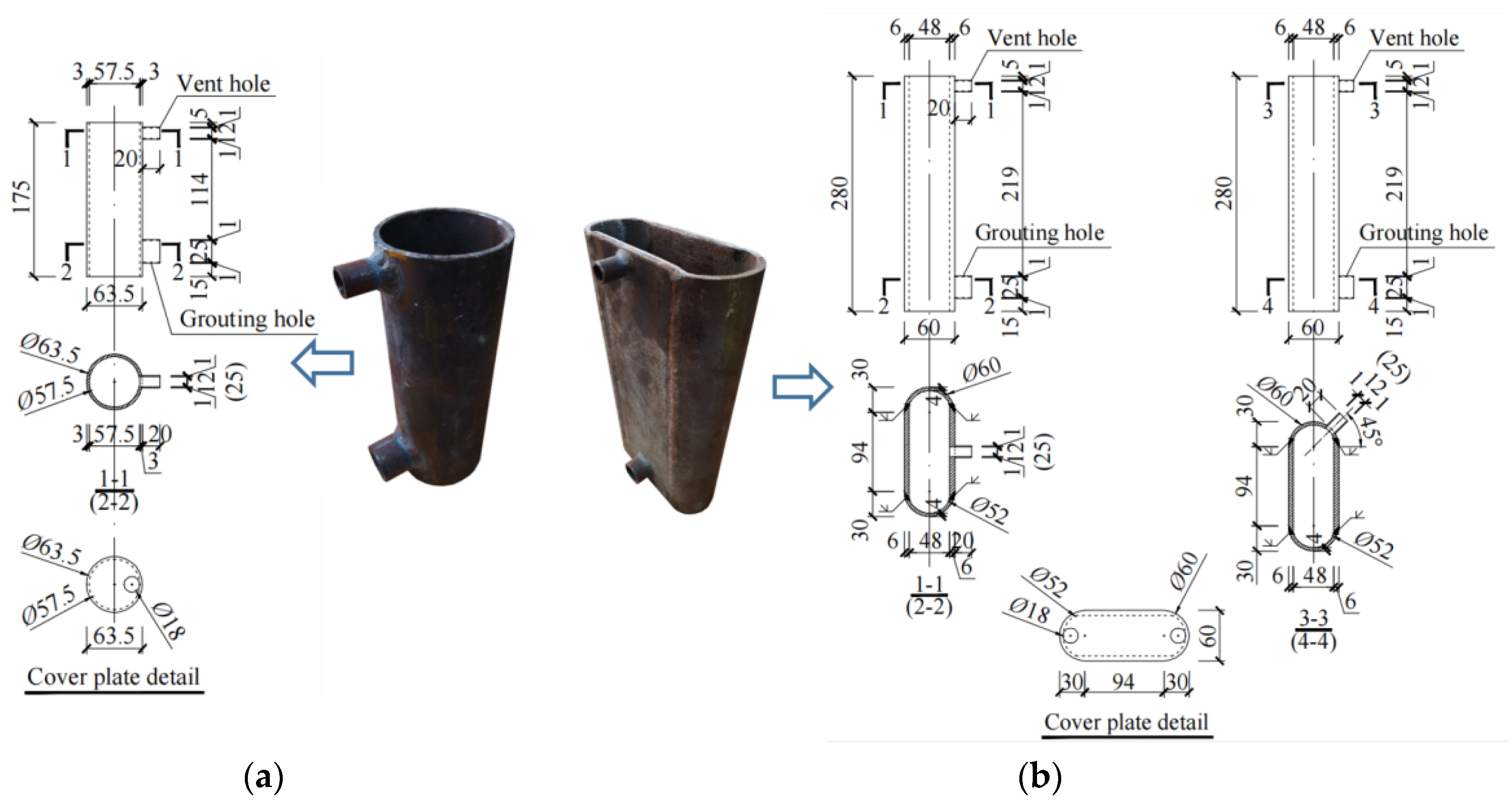
The dimensions of the type-I and type-II sleeves are shown in Figure 3, where the type-I sleeve is cut from a seamless steel pipe, and the type-II sleeve is formed by welding two steel plates and a seamless steel pipe cut along its diameter. A vent hole and a grouting hole are respectively formed in the side walls near the top and bottom of the sleeve. To ensure the quality and efficiency of grouting, the inner diameter of the grouting hole (25 mm) is larger than the inner diameter of the vent hole (12 mm). In addition, in order to prevent the concrete from entering the inside of the sleeve when the component is poured, a cover plate with thickness of 2 mm is attached to the top of the sleeve, and a round hole 4 mm larger than the diameter of the rebar is drilled on the edge of the cover plate to facilitate the insertion of the pre-embedded rebar into the sleeve. Considering the feasibility of grouting and plugging of tunnels during construction, the grouting holes and vent holes of all sleeves were placed on the inner corner side of the L-shaped shear wall in the design.

2.2. Material Properties

The strength grade of the rebar is HRB400, where HRB stands for hot-rolled ribbed rebar. The steel grade of the sleeve is Q235B, where Q and B represent the yield strength and quality grade of the steel, respectively. The average yield strength (i.e., fy) and average ultimate strength (i.e., fu) of the rebars and steel of the sleeves were measured by uniaxial tensile tests, as shown in Table 2.
The base beam of the specimen is made of C50 concrete, and the concrete strength grade of the shear wall and loading beam is C40, where C40 and C50 indicate that the standard compressive strength of a concrete cube is 40 MPa and 50 MPa, respectively. The average values of the compressive strength of the 150 mm × 150 mm × 150 mm cube specimens of the shear wall and the load beam are 48.1 MPa and 60.8 MPa during the test, respectively. Chinese concrete design code [29] points out that the axial compressive strength and tensile strength of concrete can be obtained from the modified cube compressive strength. Therefore, on the basis of the average compressive strength of cube obtained by the test, it can be calculated that the axial compressive strength of C40 concrete is 32.2 MPa by multiplying the correction coefficient, and the axial tensile strength is 2.89 MPa.
H40-type high-strength non-shrinkage grouting material is used in this test. The flexural strength and tensile strength of 40 mm × 40 mm × 160 mm and 150 mm × 150 mm × 150 mm specimens are measured to be 8.7 MPa and 4.3 MPa during the test, respectively. In addition, the axial compressive strength of the 100 mm × 100 mm × 300 mm non-standard specimens is 54.9 MPa.

2.3. Experimental Setup and Loading Sequence

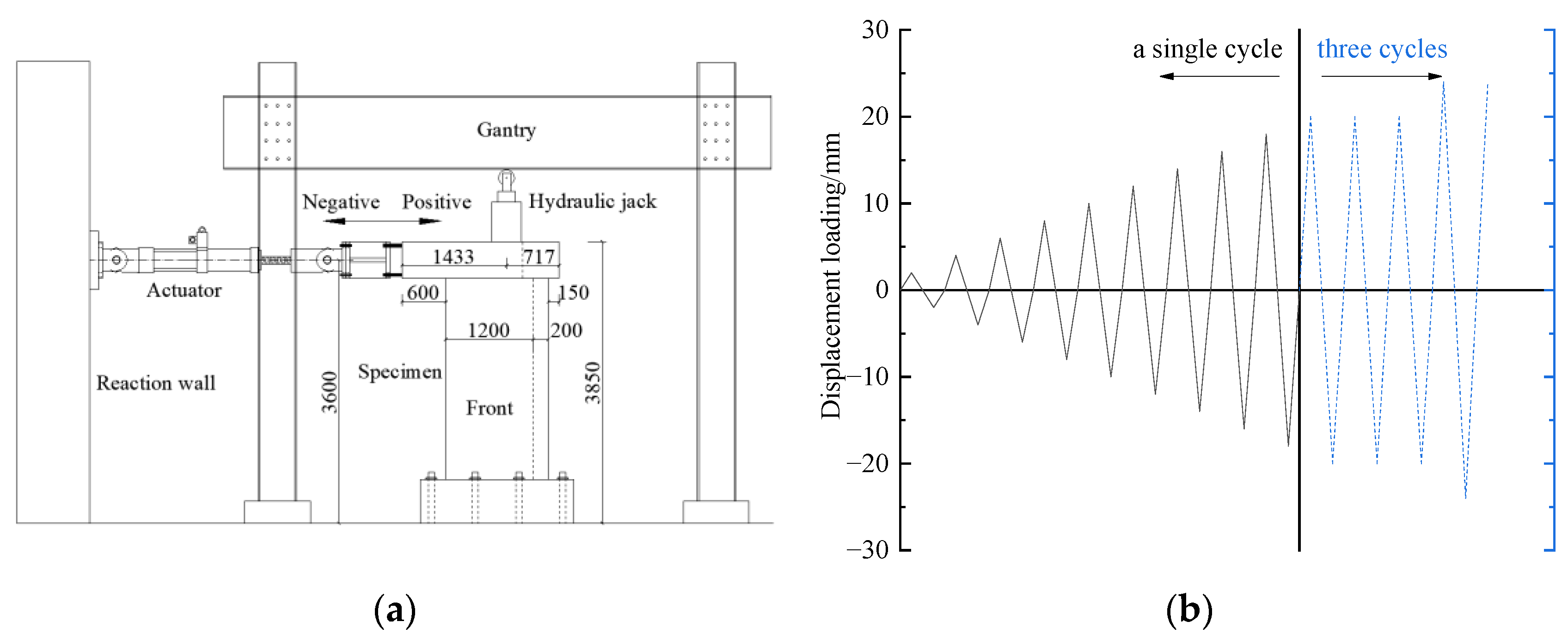
Figure 4 shows the test equipment and loading program. The specimen was anchored to the ground by bolts, and the horizontal and vertical loads were applied by two actuators and a hydraulic jack, respectively. For the experimental design value of the axial compression ratio, a value of 0.5 was chosen. The axial compression ratio [30] can be expressed as
n = N f c A
where n is the axial compression ratio, A is the full cross-sectional area of the specimen, i.e., 3.6 × 105 mm2, and fc is the design value of the axial compressive strength of C40 concrete [29], i.e., 19.1 MPa. It can be calculated that the design value of axial force N of all specimens is 3438 kN. The horizontal cyclic loading of the specimen is controlled by displacement, and positive displacement is first applied in each loading step, as shown in Figure 4b. The first step displacement is 2 mm, and when the displacement is less than 20 mm, the displacement increment of each step is 2 mm with one cycle. When the displacement is greater than or equal to 20 mm and less than 36 mm, the displacement increment of each step is 4 mm with three cycles. In the subsequent loading cycles, the displacement increment of each step was 6 mm with three cycles, and the loading was not completed until the bearing capacity of the specimen dropped to 85% of the peak load for the first time [31].

2.4. Arrangement of Measuring Points

The arrangement of the displacement gauges is shown in Figure 5. Eight displacement measuring points D-1 to D-8 were arranged corresponding to each specimen. Among them, D-1 to D-4 were used to measure the lateral displacement of the specimen under loading, and D-5 to D-6 and D-7 to D-8 were installed to record the out-of-plane displacement and the oblique deformation of the specimens, respectively. In order to measure the strain variation of the longitudinal rebars of LAPC-1 and LAPC-2, two positions were selected to arrange the strain gauges, one of which was 10 mm above the sleeve, and the other was 10 mm above the foundation.

3. Results and Discussion

3.1. Failure Modes

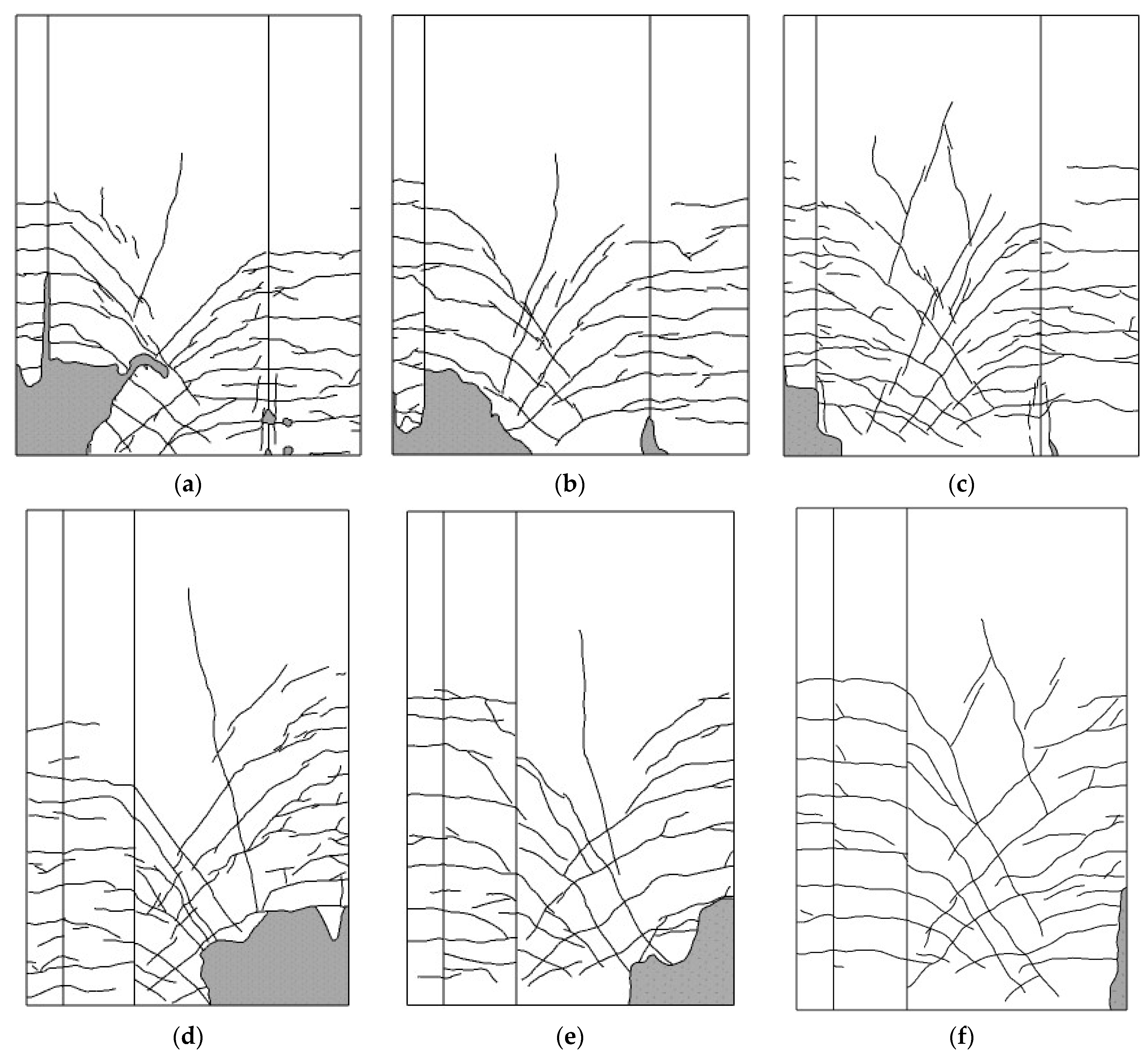
Figure 6 shows the crack distribution of LSW, LAPC-1, and LAPC-2 specimens at the ultimate displacement. It can be seen that the development pattern of cracks in each of the prefabricated walls were basically the same as that of the cast-in-place wall. The horizontal cracks first appeared at the edges of both sides of the specimens, and then gradually developed obliquely towards the middle of the wall with the increase of loading displacement. Finally, the torsional oblique cracks with a large inclination angle appeared in the middle of the walls, and the ultimate failure pattern of the specimens was bending-shear failure.

3.1.1. Specimen LSW

When the horizontal displacement reached 6 mm, an initial horizontal crack occurred at a height of about 350 mm from the top surface of the base beam on the left side of the LSW specimen (i.e., the straight-edge member). When the horizontal displacement was 8 mm, a horizontal crack appeared at the bottom of the right side of the shear wall (i.e., L-shaped-edge member). As the displacement level reached 10 mm, the original crack on the left side of the shear wall extended obliquely to the top surface of the foundation along the direction of 45°. At the same time, with the increase of displacement, multiple horizontal cracks appeared on both sides of the wall. The longitudinal reinforcement on the left side of the shear wall yielded in tension at a displacement level of 16 mm, and with the increase of loading displacement, multiple 45° inclined cracks appeared on the shear wall. When the loading level was 24 mm, vertical cracks in concrete under compression appeared at the bottom of the left and right sides of the specimen, and the oblique cracks on both sides of the specimen intersected approximately at the centroid of the wall. When the loading displacement approached 32 mm, the concrete in the compression zone began to spall off, which indicated that the outermost concrete in the compression zone had reached the ultimate strain. As the loading displacement reached 48 mm, during the second cycle of negative loading, the concrete on the left side of the wall was crushed and fell off in a large area, and the rebars buckled, which indicated that the wall reached the limit state.

3.1.2. Specimen LAPC-1

As the loading displacement reached 6 mm, the first horizontal crack appeared on the left side of the LAPC-1 specimen, which was about 480 mm above the base beam. When the loading displacement was 8 mm, two horizontal cracks appeared on the right flange of the specimen at about 200 mm and 350 mm above the foundation. When the loading displacement reached 10 mm, the horizontal crack on the back of the straight-edge member of the specimen extended obliquely at 45° to the top of the sleeve. In addition, cracks occurred on the upper joint surfaces of the left and right grouting joints of the specimen. The longitudinal reinforcement of the straight-edge member of the wall yielded at a displacement level of 16 mm. With the further increase of the displacement, the horizontal cracks on the right side of the wall developed obliquely at 45°. When the loading level was 24 mm, vertical cracks of concrete under compression appeared on the right side of the wall, and small pieces of grouting layer spalled off. At the same time, the diagonal cracks on the left and right sides of the wall intersected approximately at the centroid of the wall. When the displacement increased to 32 mm, the small pieces of concrete in the compression zone were crushed and fell off. It is worth noting that the wall and grouting layer were significantly pulled apart at a loading level of 36 mm. When the loading level was 42 mm, an oblique crack developed at about 70° in the middle of the wall. After that, the concrete in the compression zone on the left side of the wall was crushed in a large area, accompanied by a clicking sound and buckling of the rebars, and the wall reached the limit state at a displacement level of 48 mm.

3.1.3. Specimen LAPC-2

The failure process of the LAPC-2 specimen was basically the same as that of LAPC-1, but the difference was that the cracking displacement of the grouting layer and the ultimate failure displacement of LAPC-2 were larger, which were the loading level of 20 mm and 54 mm, respectively.
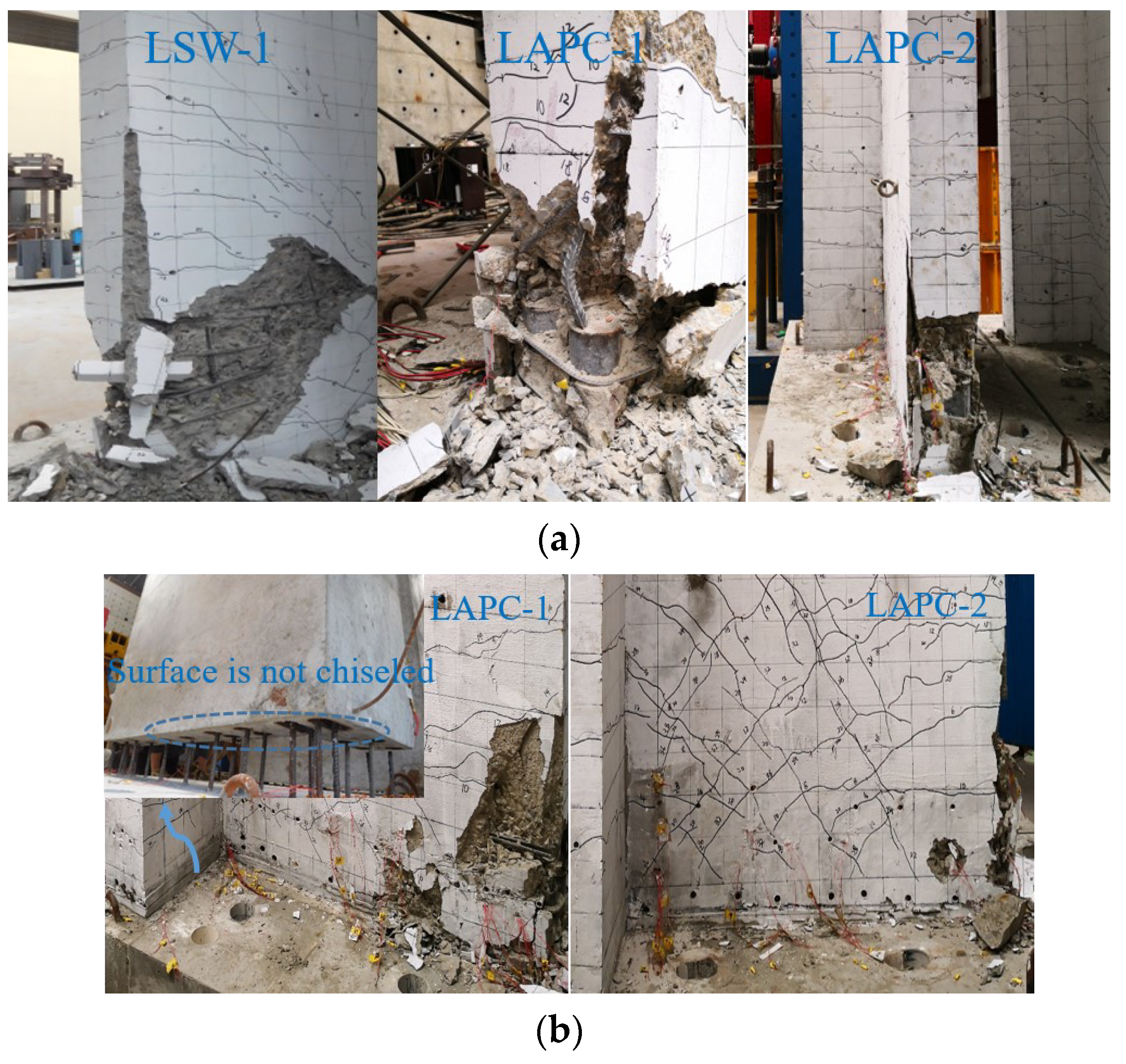
The failure of the root of the L-shaped shear wall and the grouting joint is shown in Figure 7. It can be seen that concrete crushing and rebar buckling occurred in the straight-edge members of the prefabricated and cast-in-place specimens, and the concrete damage of this prefabricated specimen was mainly concentrated in the range from the bottom of the wall to 300 mm higher than the top of the sleeve. However, the damage of the cast-in-place specimen occurred at the bottom of the wall, which was manifested as concrete crushing and spalling, and reinforcement buckling above the stirrup densification area (i.e., 220 mm to 320 mm above the foundation beam). Compared with the cast-in-place specimen, the concrete above the sleeve was crushed in the prefabricated wall, and then the concrete outside the sleeve was peeled off, but the sleeve was not significantly damaged. Eventually, the rebars above the sleeves of the precast wall buckled, indicating that the wall had reached its limit state. The reason was that the APC sleeve restrained the deformation of the rebar and grout, which made the weak section move up to the top surface of the sleeve. Similarly, reference [25] showed that concrete damage of straight prefabricated shear walls was mainly concentrated in the range from the bottom of the wall to 300 mm higher than the top of the sleeve, indicating that this range was the weak part of the prefabricated specimen. It can be seen from Figure 7a that the spalling of the concrete outside the sleeve was more serious at the limit state. This was mainly due to manufacturing error, which made the spacing of stirrups within the height range of the sleeve locally larger, and the deformation capacity of the outer concrete was poor. Compared with this test, in the reference [25], stirrups with a spacing of 50 mm were arranged within the height range of the sleeve in the prefabricated wall, and the concrete outside the sleeve was only partially damaged at the limit state. Therefore, proper densification of stirrups within the height range of the sleeve can effectively improve the bonding performance of the external concrete.
At the limit state, the grouting material of the joint on the left and right sides of the prefabricated wall was crushed and peeled off, while the grouting material of the joint in the middle of the specimen was not significantly damaged, as shown in Figure 7b. The lower surface of the precast wall (that is, the upper surface of the grouting joint) was not chiseled, forming a horizontal through crack, but the wall did not experience obvious shear slip. Since the grouting material in the sleeve and the joint were poured at the same time to form a whole, which played a role similar to the occlusal teeth, the shear bearing capacity of the joint was improved. The lower surface of the joint of the prefabricated wall and the interface of the bottom of the cast-in-place wall (both of which had been chiseled) did not have obvious cracks, indicating that the chisel can effectively improve the bonding strength between the grouting material and the concrete. Similarly, the surface of the concrete at the joint was chiseled to effectively avoid premature cracking of the joint surface in straight prefabricated walls [25]. In addition, the rebar in the sleeve was not pulled out at the limit state, and the sleeve had no obvious deformation, indicating that the sleeve had good mechanical properties.

3.2. Hysteresis and Skeleton Curves

The horizontal force-displacement hysteresis curves and skeleton curves of specimens at the vertex section are shown in Figure 8. It can be seen that the shapes of the hysteresis curves of the cast-in-place wall and the prefabricated walls were basically the same, and the hysteresis curves in the later stage of loading had a certain degree of pinching, which was mainly due to the development of concrete diagonal cracks and local crushing. With the increase of the loading displacement, the hysteresis curves gradually tended to be full, and the area of the positive hysteresis curves of the specimens were larger than that in the negative direction, indicating that the energy consumption in the positive direction was larger. It is obvious that the bearing capacity of the specimens LSW and LAPC-1 decreased significantly during the negative loading in the later stage, resulting in a larger enclosing area of the hysteresis loop. Comparing the failure phenomenon of straight-edge members of the LAPC-1 and LAPC-2 specimens, it was found that LAPC-1 did not actually set stirrups within 50 mm above the sleeve due to manufacturing errors, resulting in rapid failure of LAPC-1 after buckling of rebars during negative loading. Due to the restraint of stirrups, the buckling section of stirrups moved upward when LSW was damaged, and the bearing capacity of LAPC-2 still had a certain safety reserve in the ultimate state. Therefore, it was suggested that the distance between the first stirrup above the edge-member sleeve and the upper surface of the sleeve should not be greater than 50 mm.
It can be seen from Figure 8d that the skeleton curve of each specimen before cracking was basically a straight line, and the skeleton curves of LSW and LAPC-1 were basically consistent. As the displacement increased, the load and stiffness values of the positive skeleton curve of LAPC-2 were greater than those of the other two specimens during positive loading, and the negative skeleton curve was basically consistent with the other two specimens before the yield displacement (at a displacement level of 16 mm). However, the ultimate bearing capacity and ultimate load displacement were larger than those of LSW and LAPC-1. In addition, during the positive loading, the bearing capacity of each specimen increased with the increase of displacement, while the bearing capacity gradually decreased after the peak load under negative loading, as shown in Figure 8d. This was mainly caused by the asymmetric geometric property of the L-shaped shear wall. Larger compression capacity was provided in the L-shaped-edge member due to the larger concrete area and more rebars, which made the specimen fail to reach the peak load during the positive loading.

3.3. Bearing Capacity

Figure 8 shows the cracking load, yield force, and peak force during loading. When the first horizontal crack appeared in the tensile zone of the specimen, the corresponding horizontal force was called the cracking load. The corresponding horizontal force was the yield load, when the outermost rebar of the specimen yielded. The peak load was the maximum horizontal force that the specimen could resist.
It can be seen from Figure 8 that the cracking load of the prefabricated walls were higher than that of the cast-in-place wall, which was mainly because the existence of the sleeve and the grouting material restricted the longitudinal deformation of the concrete. The negative cracking load of specimen LAPC-2 was lower than that of the other two specimens due to the thin concrete cover of the L-shaped-edge member and the influence of loading eccentricity.
The positive yield load of each specimen was less than the negative yield load, and the peak load was not reached during positive loading. This was due to the fact that the L-shaped-edge member had a larger concrete cross-section and more rebars, leading to a higher bearing capacity. For prefabricated components, the existence of the sleeve and the grouting material improved the bearing capacity of the compression area at the bottom of the wall. Due to the large cross-sectional area of the type-II APC sleeve and grouting material in specimen LAPC-2, the concrete in the compression zone was more constrained, so the yield load was higher than that of specimen LAPC-1. Furthermore, due to the longer length of the type-II APC sleeve, the weak section (the top surface of the sleeve) moved up more during failure, so the peak load was higher than that of the other two specimens. Since the stirrups and the horizontally distributed rebars at the bottom of each wall were densified, the densification of the rebars could improve the bearing capacity of the cast-in-place wall and prefabricated walls. However, owing to the effect of the sleeves, the densified rebars had little effect on the bearing capacity of the prefabricated specimens, which caused the yield load and the peak load of specimen LSW and specimen LAPC-1 to be similar.
According to the Chinese standard [30], the peak load of the cast-in-place specimen can be calculated as follows:
N A s f y A s σ s N s w + α 1 f c b w x M A s f y ( h w 0 a s ) M s w + α 1 f c b w x ( h w 0 x 2 ) N ( h w 0 h w 2 ) i f   x ξ b h w 0 σ s = f y N s w = ( h w 0 1.5 x ) b w f y w ρ w M s w = 1 2 ( h w 0 1.5 x ) 2 b w f y w ρ w
where N and M are axial force and bending moment of cross-section, respectively. f y and f y are the tensile strength and compressive strength of reinforcement, respectively. A s and A s are the sectional areas of longitudinal reinforcement in tension and compression zones, respectively. a s is the distance from the resultant force of the compressive reinforcement to the edge of the section. b w is the thickness of the wall, and h w 0 is the effective depth of the section. f y w and ρ w are the design value of strength and reinforcement ratio of vertically distributed reinforcements in the wall, respectively. ξ b is the critical relative compression depth, and ξ b = 0.518 . x is the height of the compression zone of concrete. α 1 is the coefficient of the rectangular stress diagram, which can be taken as 1 if the concrete strength grade is less than C50.
According to the test values of concrete and rebars in Section 2.2, the calculated value by Formula (2) of the peak load of the specimens can be obtained as 745.31 kN. It can be calculated that the test values of the peak loads of the specimens LSW, LAPC-1, and LAPC-2 are 1.28, 1.26, and 1.39 times the calculated values, respectively, indicating that the current code can be used to calculate the large eccentric bending capacity of L-shaped prefabricated walls.

3.4. Strength Degradation Coefficient

The strength degradation coefficient [31] was used to measure the degradation of the bearing capacity of the specimens in the same loading stage, and its expression is as follows:
λ i = F j i F j i 1
where F j i is the peak load of the i cycle at the j loading stage, and F j i 1 is the peak load of the i − 1 cycle at the j loading stage.
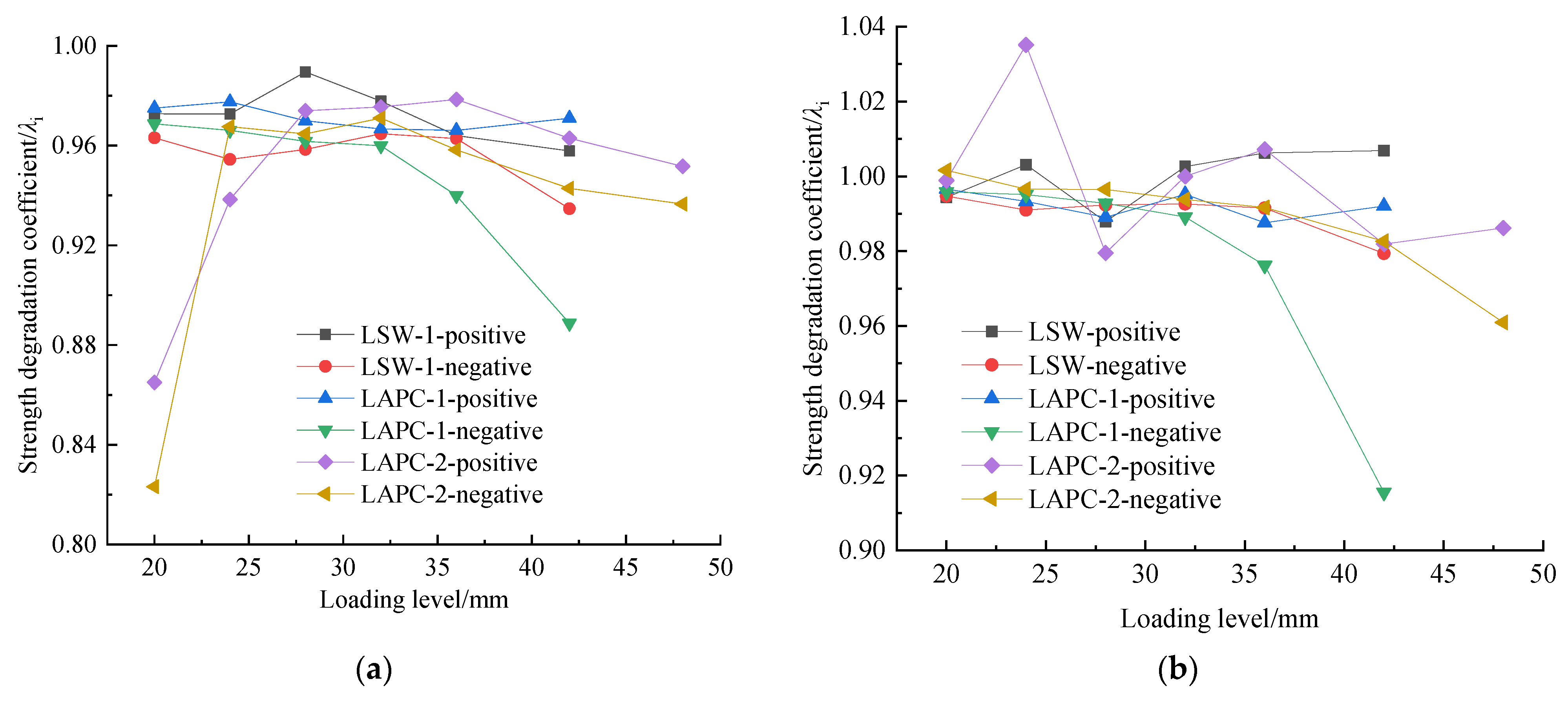
Figure 9 shows the strength degradation of each specimen at different loading levels. It can be seen that the strength degradation coefficient of each specimen was similar, and the strength degradation coefficient of the L-shaped shear wall under positive loading was basically larger than that in the negative direction, that is, the strength degradation in the negative direction was more serious than that in the positive direction. This was mainly due to the fact that the concrete damage of the straight-edge members of the specimen was more serious than that of the L-shaped-edge members. In general, the strength degradation coefficient at the third cycle of the peak load of each specimen was greater than that at the second cycle, indicating that the strength degradation tended to slow down with the increase of the number of cycles.
It can be seen from Figure 9b that there were values with a degradation higher than 1. Based on the experimental phenomenon, at the loading displacement of 20 mm, the longitudinal reinforcement in the straight-edge member of the specimen has yielded. In the process of repeated loading, the reinforcement may undergo strain hardening, which will lead to the increase of the strength of the reinforcement. Therefore, the strength degradation coefficient of the specimen may be greater than 1, which indicated that the strength of the specimen was basically not degraded.

3.5. Stiffness

The stiffness degradation [10] of the specimen was measured by the secant stiffness of the skeleton curve, which can be calculated as follows:
K i = F i X i
where Fi is the peak load of the i loading cycle in the positive or negative direction, and Xi is the displacement value corresponding to Fi.
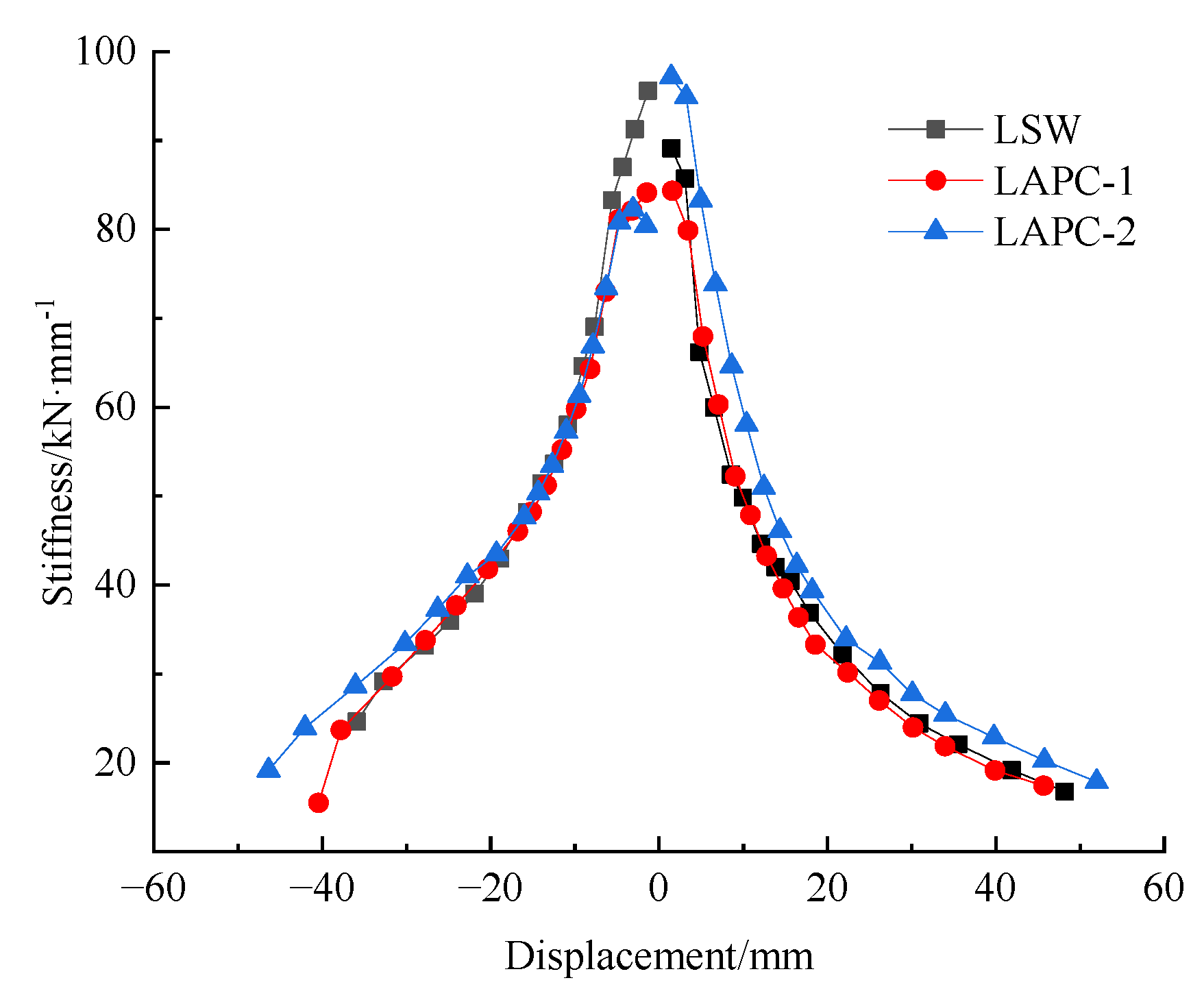
Figure 10 shows the stiffness degradation curves of the specimens, and it can be seen that the shape of the stiffness degradation curve of each specimen was basically the same. The stiffness degradation was slow before cracking, and the stiffness of the specimen decreased rapidly with the continuous development of concrete cracks. After the specimen reached the yield displacement, the crack development tended to be stable, and the stiffness decreased slowly. In general, the stiffness degradation curves of specimens LSW and LAPC-1 were basically consistent, and the stiffness of specimen LAPC-2 was slightly larger than that of other specimens. This was because the size of the type-II sleeve was larger than that of the type-I sleeve, which made the rigidity of specimen LAPC-2 larger than that of LAPC-1.

3.6. Deformation and Ductility

The vertex displacement angle of the specimen was defined as θ = Δ / H , where Δ is the lateral displacement of the loading beam, and H is the height from the center of the loading beam to the upper surface of the base beam. The ductility coefficient can be defined as μ = Δ u / Δ y to measure the plastic deformation capacity of the specimen, where Δ u is the lateral displacement corresponding to the ultimate state of the specimen, and Δ y is the lateral displacement corresponding to the yield load of the specimen. The corresponding loading beam displacement Δ , vertex displacement angle θ , and ductility coefficient μ of all specimens at different stages (i.e., cracking, yielding, peak, and ultimate stages) are shown in Table 3.
According to Table 3, the positive and negative displacements and displacement angles of the prefabricated walls (except for the negative loading of specimen LAPC-2) at the cracking stage were generally larger than those of the cast-in-place wall, which was mainly due to the longitudinal deformation of the concrete restrained by the sleeves.
The yield displacement and ultimate displacement of the specimens LAPC-1 and LSW were not significantly different, both smaller than LAPC-2, and the vertex displacement angle of the prefabricated wall was larger than that of the cast-in-place wall at the ultimate state, indicating that the deformation capacity of the prefabricated wall was better than that of the cast-in-place wall. The displacement angle of each specimen at the ultimate state was greater than the elasto-plastic inter-story displacement angle limit of 1/120 (1/100) [32] of the shear wall (frame-shear wall) structure under the action of rare earthquakes, which indicated that the specimen had good deformation ability at the elasto-plastic stage.
The ductility coefficient of each specimen was greater than 2, and the ductility coefficient of the prefabricated walls was higher than that of the cast-in-place wall, which indicates that the deformation capacity of the prefabricated walls was better than that of the cast-in-place wall. However, in reference [10,16], the deformation capacity of the prefabricated walls connected with traditional grouted splice connectors was lower than that of the cast-in-place wall due to the weak constraint of the region near the sleeve. The reason was that the APC sleeve and stirrups enhanced the confinement of the concrete at the bottom of the prefabricated specimens, and the type-II sleeve had stronger constraint ability due to its larger size, which made the bearing capacity decrease more slowly, and the ultimate displacement was larger under the ultimate load.

3.7. Energy Dissipation Capacity

The energy dissipation capacity of the specimens was evaluated by the equivalent viscous damping coefficient ζ eq [31], which can be calculated as follows:
ζ eq = S ABCD 2 π ( S OBE + S ODF )
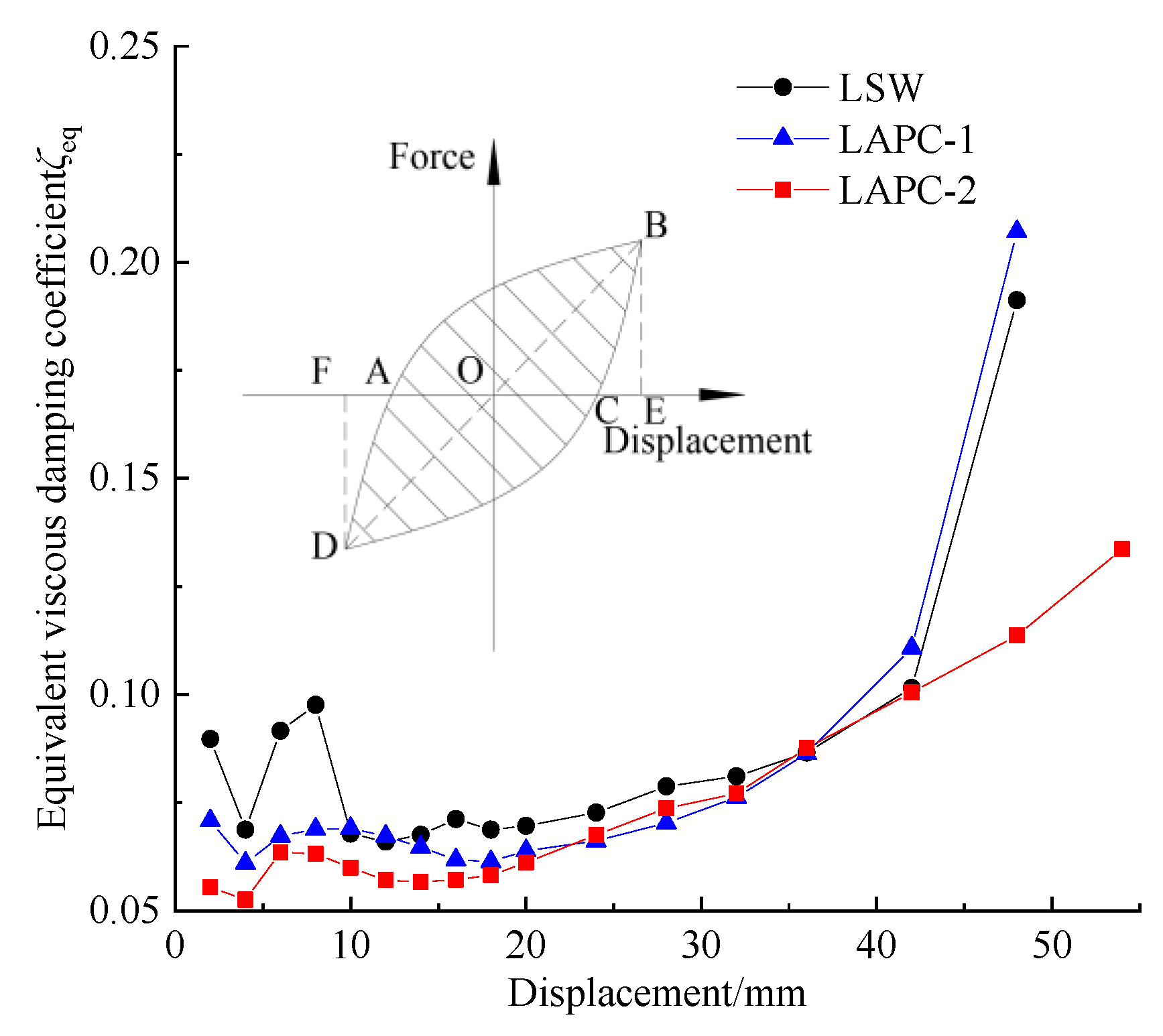
where SABCD is the area of the hysteresis loop, and SOBE and SODF represent the area of the triangle in Figure 11. Among the loading levels of the three cycles, the specimens had damage accumulation in the second and third loading cycles, so only the first loading cycle was considered in the calculation. The relationship between the equivalent viscous damping coefficient ζ eq of each specimen and the horizontal displacement is shown in Figure 11.
In the previous research on the prefabricated wall connected with traditional grouted splice connectors [16], the equivalent viscous damping coefficient of the prefabricated walls was lower than that of the cast-in-place wall at the later stage of test due to the slip of the connecting reinforcements and the larger crack width of the post-cast joint. In this test, it can be seen from Figure 11 that the equivalent viscous damping coefficient of all specimens increased with the increase of the horizontal displacement after the reinforcement yielded, and the equivalent viscous damping coefficient–horizontal displacement curve of LAPC-1 was similar to that of LSW. However, the equivalent viscous damping coefficient of specimen LAPC-2 was smaller than that of the other specimens at the later loading stage. This was mainly due to the larger crack width at the grouting joint during the failure of specimen LAPC-2, which led to the reduction of the energy dissipation capacity of the specimen to a certain extent. Therefore, to improve the bonding property of the surface of the grouting joint, it is recommended that the bottom of the prefabricated specimen and the top surface of the foundation be properly chiseled.
In reference [25], the spacing of stirrups and horizontally distributed reinforcements at the bottom of prefabricated walls was 50 mm, while that of the cast-in-place wall was 100 mm. The results showed that the energy dissipation capacity of straight prefabricated walls connected with APC connectors was better than that of the cast-in-place wall. Similarly, in practical projects, the spacing of stirrups and horizontally distributed reinforcements at the bottom of the cast-in-place wall were not encrypted. However, in this test, in order to compare with the prefabricated wall, the stirrups and horizontally distributed reinforcements at the bottom of the cast-in-place wall were encrypted with a spacing of 50 mm, which resulted in the higher energy dissipation capacity of the cast-in-place wall to some extent. The equivalent viscous damping coefficient ζ eq of each specimen at different stages is shown in Table 4. It can be seen from Table 4 that, at the same loading stage, the viscous damping coefficients of all specimens were basically the same before the failure of specimens, which indicates that they had similar energy dissipation capacities on the whole.

3.8. Strain of Rebars

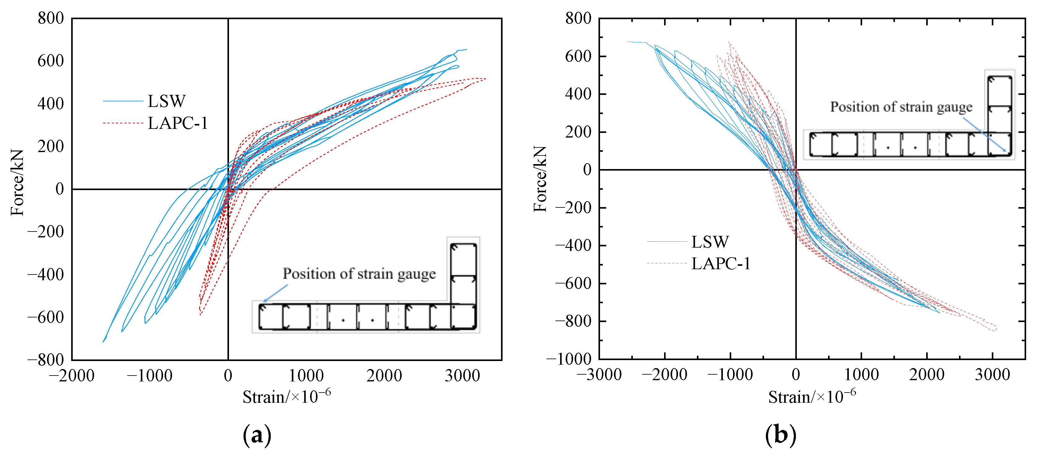
The force–strain curves of the outermost longitudinal rebars of the edge members of the specimens LSW and LAPC-1 at the position of 10 mm above the base beam are shown in Figure 12, where the tensile strain was defined as a positive value and the compressive strain was negative. The yield strain of the rebar measured by the test was about 3000 × 10−6. Due to the poor correlation between the strain and the horizontal force after the rebar yielded, the data with a strain less than 3000 × 10−6 was considered in the analysis. It is apparent from Figure 12 that the trend of load–strain curves of the outermost rebars of the edge members of specimens LAPC-1 and LSW was basically identical. However, when the outermost rebar was under tension, the strain value of the rebar of specimen LAPC-1 was larger, and when the outermost rebar was under compression, the strain value of the rebar of specimen LAPC-1 was smaller. The main reason was that high-strength grouting materials were used in the joints of prefabricated specimens, which reduced the force of rebars in the same section to some extent. In addition, the crack occurred early at the grouting joint of the prefabricated specimen LAPC-1, which made the stress of the rebar during tension greater.
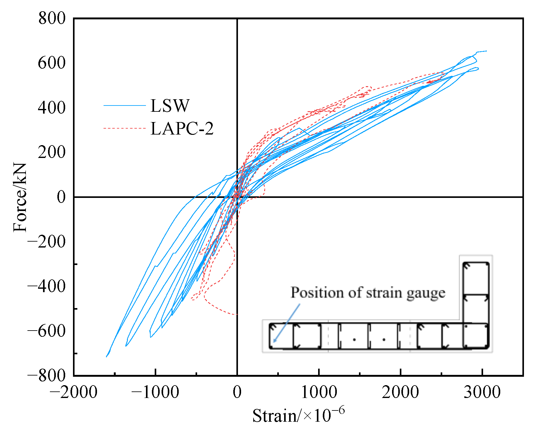
Figure 13 shows the force–strain curves of the outermost longitudinal rebars of the edge members of specimens LSW and LAPC-2 at the position of 10 mm above the base beam. Due to the problem of the data acquisition system, the strain data of the outermost longitudinal rebars at the corner of the L-shaped-edge members of LAPC-2 could not be obtained. It can be seen from Figure 13 that the shape of the load–strain curves of the outermost rebars in the edge members of specimens LAPC-2 and LSW was similar. when the outermost rebar was under tension, there was a small difference between specimen LAPC-2 and the cast-in-place specimen in the strain value of the rebar, while when the outermost rebar was compressed, specimen LAPC-2 had a smaller strain value of rebar for the same reason as LAPC-1. In general, the shape of the force–strain curves of rebars at the joints of the two prefabricated specimens was similar to that of the cast-in-place specimen, indicating that the connection of the sleeves at the joints was reliable.
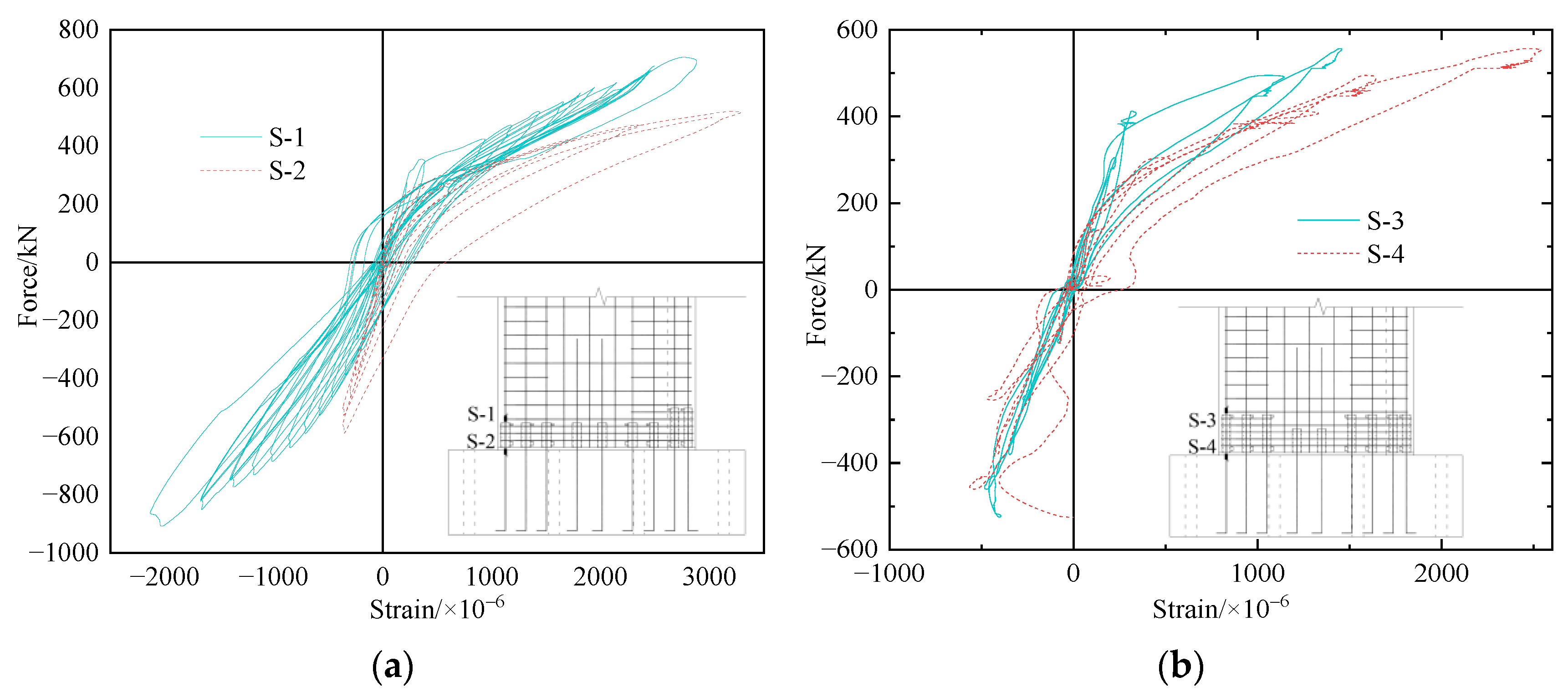
Figure 14 shows the force–strain curves of the outermost longitudinal rebars of the straight-edge members of specimens LAPC-1 and LAPC-2 at the position of 10 mm above the base beam and sleeves. It can be seen from Figure 14 that the reinforcement under the sleeve was subjected to a larger force during tension, resulting in a larger strain value of the reinforcement. In general, the shape of the force–strain curves of the reinforcement above the sleeve and the base beam was basically the same, indicating that the APC sleeve could effectively transmit the reinforcement stress in the L-shaped shear wall.
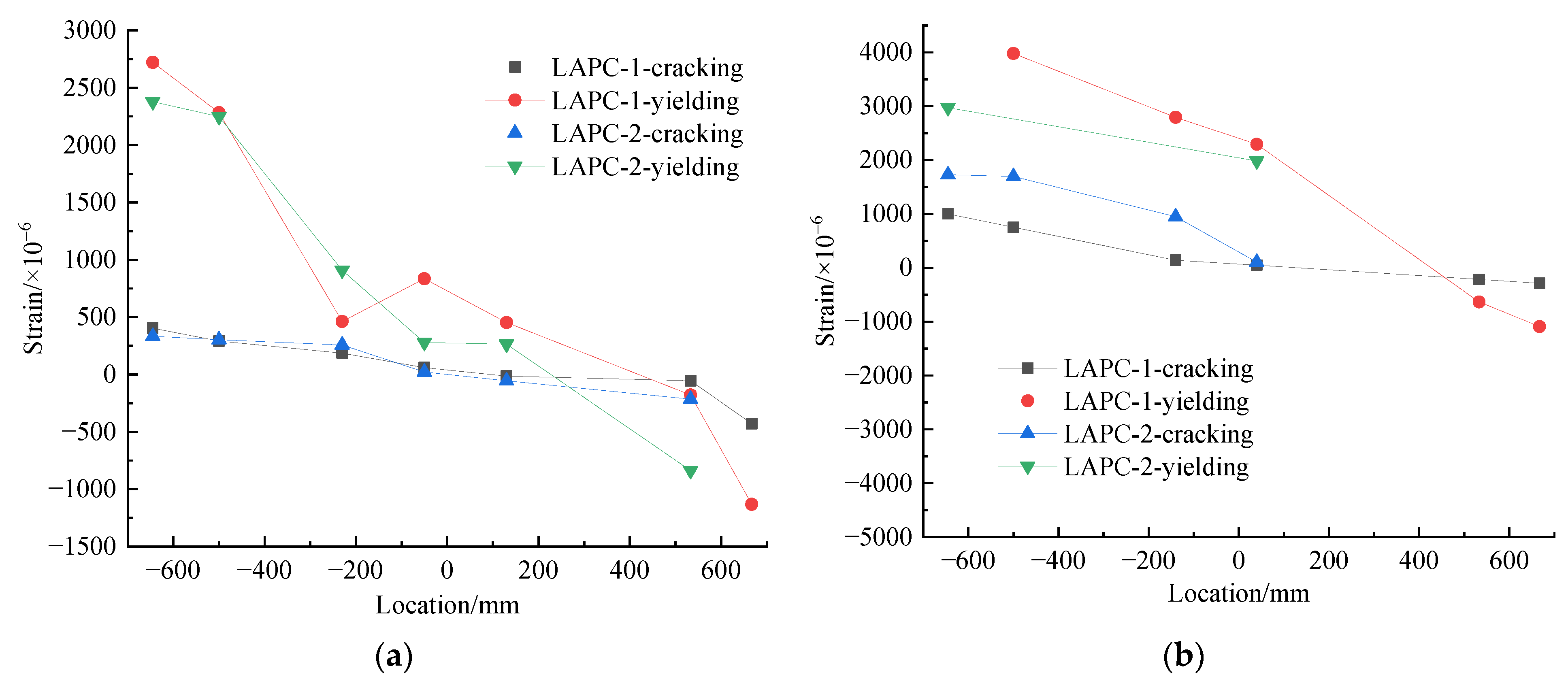
Figure 15 shows the strain distribution of longitudinal rebar along the long leg of the prefabricated walls at 10 mm above the base beam and sleeves (the coordinate at the center of the long leg is 0). Due to the failure of some strain-measuring points in the loading process, the strain values of some positions of rebars were not obtained. It was found that the strain of longitudinal rebars at the same section of the prefabricated walls was basically linearly distributed, i.e., the specimens basically satisfied the assumption of plane section before yielding, and with the increase of load, the strain value of the rebar at each position increased continuously, which indicated that the APC connectors effectively transferred the stress of rebars. In addition, the strain variation of rebars in the straight-edge member (i.e., the position is from −700 mm to −300 mm) was larger than that of the L-shaped-edge member (i.e., the position is from 200 mm to 700 mm), which was mainly due to fewer rebars and less concrete in the straight-edge member.

3.9. Out-of-Plane Torsion and Oblique Deformation of Specimens

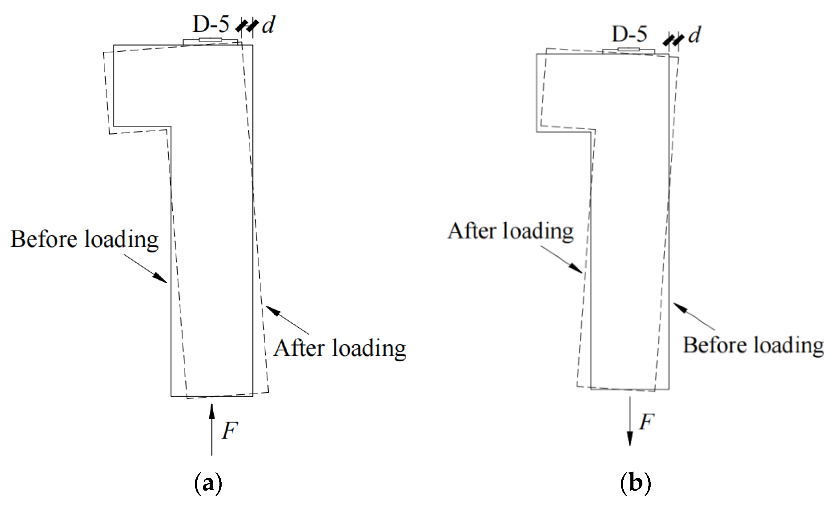
The torsion of the specimen before and after loading is shown in Figure 16. The torsion of the specimen was evaluated by the out-of-plane displacement of the loading beam relative to the base beam (obtained by the difference between measuring points D-5 and D-6), and the out-of-plane displacement generated by the clockwise rotation of the specimen was defined as positive. Figure 17 shows the relationship between the horizontal force and out-of-plane displacement of the specimen. As shown in Figure 17, the force-out-of-plane displacement curve of the L-shaped shear wall was roughly oblique.
It can be seen from Figure 17a that specimen LSW rotated counterclockwise outside the plane of the specimen under positive loading, and rotated clockwise under negative loading. When the load was small, the difference between the maximum out-of-plane displacements under positive and negative loading was not obvious, while when the load was large, the out-of-plane displacement under negative loading was significantly larger than that under positive loading, which was mainly due to the serious damage of the concrete at the root of the straight-edge member in the later loading stage. As shown in Figure 17b,c, the out-of-plane displacement of the prefabricated specimens gradually rotated counterclockwise and accumulated during the loading process, mainly due to the existence of grouting joints at the bottom of the prefabricated walls. Since the bottom of the prefabricated walls in this test was not chiseled, the accumulation of damage was prone to occur at the joint surface. When the specimen was positively loaded, the damage of the counterclockwise torsion and the accumulation of damage had appeared. Although the out-of-plane displacement of the counterclockwise torsion was reduced during the negative loading, it was still in the counterclockwise state. Therefore, the out-of-plane displacement generated by the counterclockwise rotation of the prefabricated wall was continuously superimposed when the prefabricated wall was positively loaded. The absolute value of the maximum out-of-plane displacement of the prefabricated walls was smaller than that of the cast-in-place wall, which was mainly because the sleeve and grouting material at the bottom of the prefabricated walls increased the stiffness of the specimens.
The oblique deformation curves of the shear walls are shown in Figure 18, in which the positive value of the displacement represents elongation, and the negative value represents shortening. The stress and deformation of the wall element during positive loading are shown in Figure 19. It is apparent that the measuring point D-7 was elongated under the positive loading of the specimen, and the measuring point D-8 was the opposite.
The shape of the oblique deformation curve of the prefabricated and cast-in-place specimens was similar, while the maximum tensile displacement of the measuring points D-7 and D-8 of the cast-in-place wall was larger than that of the prefabricated walls, and the maximum displacement of the compression was smaller than that of the prefabricated walls. The reason was that during the loading process, the prefabricated walls were basically in a counterclockwise torsion state outside the plane, meaning the measuring point D-7 was taken in a compressed state. Although the measuring point D-7 was stretched under positive loading, the compressive deformation was continuously superimposed due to the accumulation of damage to the grouting layer under negative loading. Therefore, the maximum compressive displacement of the prefabricated walls was greater than that of the cast-in-place wall. Similarly, the deformation of measuring point D-8 under positive loading was superimposed with the compression deformation caused by torsion, resulting in the accumulation of compression deformation. In general, the maximum absolute value of the oblique deformation of the prefabricated walls was smaller than that of the cast-in-place wall.

4. Design Recommendations

Based on the previous research experience [24,25] and the results of this test, the following suggestions are proposed for the seismic design of prefabricated concrete components connected with grouted sleeve lapping connectors:
  • In order to improve the bonding strength of the sleeve on concrete and the compressive strength of concrete, stirrups and horizontally distributed reinforcements should be encrypted within the range from the bottom of the wall to 300 mm higher than the top of the sleeve. It is recommended to adopt the design measures of stirrups and horizontally distributed reinforcements in this paper in practical engineering, that is, the space between reinforcements is 50 mm.
  • To prevent premature cracking of the grouting joint surface, the bottom of the prefabricated specimen and the top surface of the foundation should be properly chiseled. Furthermore, the bonding performance of the bonding surface can be improved by providing suitable keyways.
  • A single row or double row of sleeves can be applied to the reinforcement connection of the wall body other than the edge members in the prefabricated wall. When the part of wall body other than the edge members of the prefabricated wall is connected by a single row of sleeves, the reinforcement can be calculated by the principle of equal strength substitution.
  • It is recommended that the top of the sleeve should be provided with a 2 mm thick cover plate to prevent concrete from flowing into the sleeve during the preparation of the specimen. Based on the conventional grouting material used for the grouted splice connector, it is recommended to use a grouting material with a strength grade of at least C60. In addition, to ensure the fluidity of the grouting material in the sleeve, the maximum aggregate particle size in the grouting material should not exceed 4.75 mm.
  • In consideration of possible grout defects in the sleeve above the vent hole, the vent hole above the sleeve should be as close to the top section of the sleeve as possible. Furthermore, it is recommended that the length of the sleeve above the vent hole should not be considered in the calculation.

5. Conclusions

Through the quasi-static test of a cast-in-place L-shaped shear wall and two prefabricated L-shaped shear walls, one connected by type-I and one by type-II APC connectors, the main conclusions were as follows:
  • The final crack distribution and failure modes of the L-shaped prefabricated walls were basically the same as those of the cast-in-place wall, and all the specimens had suffered bending-shear failure. The difference was that the failure of the cast-in-place specimen occurred at the root of the wall limb, while the failure of the prefabricated specimens occurred at the top of the sleeve due to the constraints of the sleeve.
  • At the ultimate state, a horizontal through crack was formed between the upper surface of the grouting joint and the prefabricated walls. Although the walls did not undergo obvious shear slip due to the action of the occlusal teeth at the joint, accumulated damage occurred in the out-of-plane displacement of the specimens.
  • The bearing capacity, stiffness, ductility, and energy dissipation capacity of the prefabricated specimen connected by type-I sleeve were comparable to those of the cast-in-place wall, while the prefabricated wall connected by type-II sleeve showed greater bearing capacity and stiffness, as well as better ductility.
  • Type-I and type-II APC sleeves could effectively transfer reinforcement stress in L-shaped shear walls, and the prefabricated specimens basically met the assumption of plane section before yielding, and the sleeves were not significantly damaged during the whole loading process.
  • Out-of-plane torsion occurred in both the cast-in-place and the prefabricated walls, but the maximum absolute value of out-of-plane displacement and oblique deformation for prefabricated walls was smaller due to their high stiffness.
In summary, due to the limited number of specimens and range of research parameters in this experiment, more types of specimens and research parameters, such as reinforcement diameter, shear–span ratio, axial compression ratio, and reinforcement ratio, need to be studied through tests and numerical simulations. In addition, the shear properties of the joints in the prefabricated walls need to be evaluated more rigorously. However, this experiment provides benchmark data for further numerical simulations and theoretical research on prefabricated components connected with APC connectors, and provides theoretical guidance for engineering applications of this connection technology.

Author Contributions

Q.Y. proposed the method, conceived the experiments, analyzed the data, made the conclusions, and wrote the paper. Z.T. carried out pseudo-static experiments, analyzed the data, and wrote the paper. X.Z. conceived and designed the experiments. Z.Z. and B.F. conducted the analysis about the experimental phenomenon. Z.C. checked and revised the paper. All authors have read and agreed to the published version of the manuscript.

Funding

This work was supported by the Natural Science Foundation of Shanghai (the Science and Technology Program of Shanghai) with grant number 21ZR1468300.

Institutional Review Board Statement

Not applicable.

Informed Consent Statement

Not applicable.

Data Availability Statement

Not applicable.

Acknowledgments

We thank Xilin Lv (University of Tongji) for his assistance.

Conflicts of Interest

The authors declare no conflict of interest.

References

  1. Yee, A.A. Structural and economic benefits of precast/prestressed concrete construction. PCI J. 2001, 46, 34–42. [Google Scholar] [CrossRef]
  2. Xue, W.C.; Hu, X. State of the art of studies on precast concrete shear wall structures. J. Build. Struct. 2019, 40, 44–55. [Google Scholar] [CrossRef]
  3. Yee, A.A. Splice Sleeve for Reinforcing Bars. U.S. Patent 3,540,763, 27 June 1968. [Google Scholar]
  4. Ling, J.H.; Abd Rahman, A.B.; Ibrahim, I.S.; Hamid, Z.A. Tensile capacity of grouted splice sleeves. Eng. Struct. 2016, 111, 285–296. [Google Scholar] [CrossRef]
  5. Kuang, Z.P.; Zheng, G.Y. Computational and experimental mechanical modelling of a composite grouted splice sleeve connector system. Materials 2018, 11, 306. [Google Scholar] [CrossRef]
  6. Lin, F.; Wu, X.B. Mechanical performance and stress-strain relationships for grouted splices under tensile and cyclic loadings. Int. J. Concr. Struct. Mater. 2016, 10, 435–450. [Google Scholar] [CrossRef]
  7. Alias, A.; Zubir, M.A.; Shahid, K.A.; Abd Rahman, A.B. Structural performance of grouted sleeve connectors with and without transverse reinforcement for precast concrete structure. Procedia Eng. 2013, 53, 116–123. [Google Scholar] [CrossRef]
  8. Guo, T.; Yang, J.; Wang, W.; Li, C. Experimental investigation on connection performance of fully-grouted sleeve connectors with various grouting defects. Constr. Build. Mater. 2022, 327, 126981. [Google Scholar] [CrossRef]
  9. Soudki, K.A.; Rizkalla, S.H.; Leblanc, B. Horizontal Connections for Precast Concrete Shear Walls Subjected to Cyclic Deformations Part 1: Mild Steel Connections. PCI J. 1995, 40, 78–96. [Google Scholar] [CrossRef]
  10. Peng, Y.Y.; Qian, J.R.; Wang, Y.H. Cyclic performance of precast concrete shear walls with a mortar sleeve connection for longitudinal steel bars. Mater. Struct. 2016, 49, 2455–2469. [Google Scholar] [CrossRef]
  11. Ameli, M.J.; Parks, J.E.; Brown, D.N.; Pantelides, C.P. Seismic evaluation of grouted splice sleeve connections for reinforced precast concrete column-to-cap beam joints in accelerated bridge construction. PCI J. 2015, 60, 80–103. [Google Scholar] [CrossRef]
  12. Xu, L.; Pan, J.L.; Cai, J.M. Seismic performance of precast RC and RC/ECC composite columns with grouted sleeve connections. Eng. Struct. 2019, 188, 104–110. [Google Scholar] [CrossRef]
  13. Qiao, D.H.; Xu, Y.Q.; Zhang, X.; Pang, J.B.; Liu, K.; Wang, S.J. Seismic behaviour and size effect of column base joints with inverted exposed grouted sleeves. J. Build. Eng. 2022, 51, 104333. [Google Scholar] [CrossRef]
  14. Qian, J.R.; Yang, X.K.; Qin, H.; Peng, Y.Y.; Zhang, J.M.; Li, J.S. Tests on seismic behavior of pre-cast shear walls with various methods of vertical reinforcement splicing. J. Build. Struct. 2011, 32, 51–59. [Google Scholar] [CrossRef]
  15. Du, X.L.; Wu, M.; Liu, H.T. The seismic performance of precast short-leg shear wall under cyclic loading. Adv. Struct. Eng. 2021, 24, 570–582. [Google Scholar] [CrossRef]
  16. Wu, M.; Liu, X.; Liu, H.T.; Du, X.L. Seismic performance of precast short-leg shear wall using a grouting sleeve connection. Eng. Struct. 2020, 208, 110338. [Google Scholar] [CrossRef]
  17. Xu, G.S.; Wang, Z.; Wu, B.; Bursi, O.S.; Tan, X.J.; Yang, Q.B.; Wen, L. Seismic performance of precast shear wall with sleeves connection based on experimental and numerical studies. Eng. Struct. 2017, 150, 346–358. [Google Scholar] [CrossRef]
  18. Xiao, S.; Wang, Z.L.; Li, X.M.; Harries, K.A.; Xu, Q.F.; Gao, R.D. Study of effects of sleeve grouting defects on the seismic performance of precast concrete shear walls. Eng. Struct. 2021, 236, 111833. [Google Scholar] [CrossRef]
  19. Yu, Q. A New Confined Lapping Sleeve. C.N. Patent 201420656653.0, 1 April 2015. [Google Scholar]
  20. Yu, Q.; Xu, Z.Y.; Yuan, W.H.; Lv, X.L. Experimental study of grouted sleeve lapping connectors varied in two factors under tensile load. J. Harbin Inst. Technol. 2016, 48, 34–42. [Google Scholar] [CrossRef]
  21. Yu, Q.; Wei, J.W.; Wei, Y.T.; Xu, Z.Y. Experimental study of grouted sleeve lapping connectors of two bars under tensile load. J. Hunan Univ. 2019, 46, 20–32. [Google Scholar] [CrossRef]
  22. Yu, Q.; Sun, J.Q.; Xu, Z.Y.; Li, L.Z.; Zhang, Z.; Yu, S.L. Mechanical analysis of grouted sleeve lapping connector. Appl. Sci. 2019, 9, 4867. [Google Scholar] [CrossRef] [Green Version]
  23. Yu, Q.; Xu, Z.Y. Experimental study of grouted sleeve lapping connector under tensile load. Građevinar 2017, 69, 453–465. [Google Scholar] [CrossRef]
  24. Yu, Q.; Zhang, L.; Bai, S.H.; Fan, B.X.; Chen, Z.H.; Li, L.Z. Experimental study on seismic behavior of precast frame columns with vertical reinforcement spliced with grouted sleeve lapping connectors. Adv. Civ. Eng. 2021, 2021, 1549303. [Google Scholar] [CrossRef]
  25. Yu, Q.; Sun, J.Q.; Xu, X.J.; Fang, Y.Q. Experimental study on seismic behavior of precast shear walls with reinforcement spliced by grouted sleeve lapping connector. J. Tongji Univ. 2018, 46, 1348–1359+1373. [Google Scholar] [CrossRef]
  26. Xue, W.C.; Chu, M.X.; Liu, Y.N.; Hu, X. Seismic performance of new precast concrete shear wall under high axial compression ratio. J. Harbin Eng. Univ. 2018, 39, 452–460. [Google Scholar] [CrossRef]
  27. Liu, J.L.; Wang, B.M.; Chu, M.J.; Wang, B.; Zhang, P.F.; An, N.; Li, X.B. Experimental study on flexural behavior of monolithic precast concrete shear walls with mortise-tenon joints. Eng. Mech. 2021, 38, 79–87. [Google Scholar] [CrossRef]
  28. GB/T 51231-2016; Technical standard for assembled buildings with concrete structure. China Architecture and Building Press: Beijing, China, 2017. (In Chinese)
  29. GB50010-2010; Code for design of concrete structures. China Architecture and Building Press: Beijing, China, 2010. (In Chinese)
  30. JGJ 3-2010; Technical specification for concrete structures of tall building. China Architecture and Building Press: Beijing, China, 2010. (In Chinese)
  31. JGJ/T 101-2015; Specification for seismic test of buildings. China Architecture and Building Press: Beijing, China, 2015. (In Chinese)
  32. GB50011-2010; Code for seismic design of buildings. China Architecture and Building Press: Beijing, China, 2010. (In Chinese)
Figure 1. Schematic of grouted sleeve connector: (a) grouted splice connector; (b) type-I grouted lapping connector; and (c) type-II grouted lapping connector.
Applsci 13 02301 g001
Figure 2. Dimensions and reinforcements of specimens (a) Facade of LSW, (b) Facade of LAPC-1, (c) Facade of LAPC-2, (d) Section of LSW, (e) Section of LAPC-1, (f) Section of LAPC-2.
Applsci 13 02301 g002
Figure 3. Details of APC sleeves: (a) type-I sleeve; and (b) type-II sleeve.
Applsci 13 02301 g003
Figure 4. Setup of the test. (a) Loading device; (b) Loading system.
Applsci 13 02301 g004
Figure 5. Dimensions of specimens and arrangement of displacement gauges: (a) front elevation of the specimen; and (b) side elevation of the specimen.
Applsci 13 02301 g005
Figure 6. Schematic of the failure of specimens at the limit state: (a) crack development view of the front and side of LSW; (b) crack development view of the front and side of LAPC-1; (c) crack development view of the front and side of LAPC-2; (d) crack development on the back of LSW; (e) crack development on the back of LAPC-1; and (f) crack development on the back of LAPC-2.
Applsci 13 02301 g006
Figure 7. Failure of the root and grouting joint of L-shaped shear walls under ultimate load: (a) root of specimens; and (b) grouting joint of prefabricated specimens.
Applsci 13 02301 g007
Figure 8. Comparison of hysteresis curves and skeleton curves of specimens: (a) hysteresis curve of LSW; (b) hysteresis curve of LAPC-1; (c) hysteresis curve of LAPC-2; and (d) skeleton curves of the three specimens.
Applsci 13 02301 g008
Figure 9. Comparison of strength degradation coefficient of each specimen: (a) second load cycle; and (b) third load cycle.
Applsci 13 02301 g009
Figure 10. Comparison of stiffness degradation curves of specimens.
Applsci 13 02301 g010
Figure 11. Equivalent viscous damping coefficient displacement curve of specimens.
Applsci 13 02301 g011
Figure 12. Force–strain curves of the rebars of specimens LSW and LAPC-1 at 10 mm above the base beam: (a) the outermost longitudinal rebars of the straight-edge member; and (b) the outermost longitudinal rebars of the L-shaped-edge member.
Applsci 13 02301 g012
Figure 13. Force–strain curves of the outermost longitudinal rebars of the straight-edge members of specimens LSW and LAPC-2 at the position of 10 mm above the base beam.
Applsci 13 02301 g013
Figure 14. Force–strain curves of the outermost longitudinal rebars of the straight-edge member at 10 mm above the base beam and sleeves of LAPC-1 and LAPC-2: (a) LAPC-1; and (b) LAPC-2.
Applsci 13 02301 g014
Figure 15. Strain distribution of longitudinal rebars above and below the sleeves of the precast walls during cracking and yielding: (a) 10 mm above the sleeve; and (b) 10 mm above the base beam.
Applsci 13 02301 g015
Figure 16. Schematic of the torsion of the specimen before and after loading: (a) positive loading (counterclockwise); and (b) negative loading (clockwise).
Applsci 13 02301 g016
Figure 17. Force-out-of-plane displacement curves of specimens: (a) LSW; (b) LAPC-1; and (c) LAPC-2.
Applsci 13 02301 g017
Figure 18. Oblique deformation curves of specimens: (a) LSW; (b) LAPC-1; and (c) LAPC-2.
Applsci 13 02301 g018
Figure 19. Stress and deformation of the wall element under positive loading: (a) element stress; and (b) element deformation.
Applsci 13 02301 g019
Table 1. Casting method of the specimen and splicing form of the longitudinal rebar.
SpecimenConcrete CastingForm of Splicing
Straight-Edge MemberMiddle of WallL-Shaped-Edge Member
LSWCast-in-placeContinuous rebarsContinuous rebarsContinuous rebars
LAPC-1PrefabricatedSix type-I sleevesTwo type-I sleevesEight type-I sleeves and two type-II sleeves
LAPC-2PrefabricatedThree type-II sleevesTwo type-I sleevesSix type-II sleeves
Table 2. Mechanical parameters of rebars and sleeves.
MaterialDiameter/mmThickness/mmfy/MPafu/MPa
Rebar8-370633
14-540636
Steel of sleeve-3309426
-4326467
-6315449
Table 3. Ductility coefficient of specimens.
SpecimenDirectionCracking StageYield StagePeak StageUltimate Stage μ
Δ ce /mm θ ce Δ ye /mm θ ye Δ me /mm θ me Δ ue /mm θ ue
LSWPositive4.821/62212.481/240-----
Negative5.591/53718.121/16632.721/9238.901/772.15
LAPC-1Positive5.231/57413.521/222-----
Negative6.351/47217.901/16831.701/9540.451/742.26
LAPC-2Positive4.961/60514.361/209-----
Negative4.711/63718.781/16036.071/8346.361/652.47
Table 4. The equivalent viscous damping coefficient of each specimen at different stages.
SpecimenDisplacement/mm
610162436424854
LSW0.0920.0680.0710.0730.0870.1020.191-
LAPC-10.0670.0690.0620.0660.0860.1110.207-
LAPC-20.0630.0600.0570.0680.0880.1000.1140.134
Disclaimer/Publisher’s Note: The statements, opinions and data contained in all publications are solely those of the individual author(s) and contributor(s) and not of MDPI and/or the editor(s). MDPI and/or the editor(s) disclaim responsibility for any injury to people or property resulting from any ideas, methods, instructions or products referred to in the content.