Article

Clogging Prevention of Slurry–Earth Pressure Balance Dual-Mode Shield in Composed Strata with Medium–Coarse Sand and Argillaceous Siltstone

1
CCCC Second Harbor Engineering Company Ltd., Wuhan 430012, China
2
School of Qilu Transportation, Shandong University, Jinan 250002, China
*
Author to whom correspondence should be addressed.
Appl. Sci. 2023, 13(3), 2023; https://doi.org/10.3390/app13032023
Submission received: 23 December 2022 / Revised: 1 February 2023 / Accepted: 2 February 2023 / Published: 3 February 2023
(This article belongs to the Special Issue Advances in Sustainable Geotechnical Engineering)

Abstract

:
The slurry–earth pressure balance dual-mode shield has an earth pressure balance (EPB) and slurry shield functions. Based on a shield tunnel project of Guangzhou Metro Line 12 in China, this study investigates the clogging prevention of a slurry–earth pressure balance dual-mode shield in a composed stratum with medium–coarse sand and argillaceous siltstone. The results show that the slurry mode was not applicable to the composed stratum with medium–coarse sand and argillaceous siltstone. The excavated soil accumulated easily in the slurry chamber, causing shield clogging. The total thrust force of the shield increased significantly, the tunneling speed gradually decreased to 0, and the torque of the cutterhead increased slightly after the slurry shield was clogged. The fluctuation in the total thrust force, the cutterhead torque, and the tunneling speed also increased significantly. The EPB mode is recommended for composed strata with medium–coarse sand and argillaceous siltstone. The dispersible foam agent and water needed to be used for soil conditioning. The injection amount of foam and water was determined according to the status of the mud discharged by the screw conveyor. Water absorption can be used to characterize the water absorption capacity of particles larger than 0.15 mm. The ideal soil state was that the consistency index of the particles smaller than 0.15 mm was less than 0.5 to prevent the EPB shield from clogging. The water absorption of soil with a particle larger than 0.15 mm should be removed when calculating the consistency index.

1. Introduction

Shield tunneling is widely used in urban metro and municipal tunnel projects due to its high safety and efficiency [1,2]. The earth pressure balance (EPB) and slurry shields are the two most widely used types of shield machines [3,4]. Slurry is used to balance the tunneling face for the slurry shield and it can better control the surface settlement. It is applicable to a wide variety of grounds, from clay to sand and gravel, with a hydraulic conductivity (K) between 10−8 m/s and 10−2 m/s under varying charges of water. However, for ground with high silt or clay content, a problem may result in the separation plant [5]. The excavated soil is used to balance the tunneling face for the EPB shield. The EPB shield has the advantages of a small occupation area and low equipment cost. However, this type of shield easily causes a large stratum settlement [6]. The application stratum of the EPB shield is a low-permeability stratum that contains clay, silt, or fine sand. However, a shield tunneling section may contain both a water-rich gravel stratum and clayey stratum in regions with a complex and changeable geology. It is difficult to meet the requirements by using only the EPB or a slurry shield. Therefore, the dual-mode shield with the functions of the EPB and slurry shield was produced [7]. The slurry–earth pressure balance dual-mode shield not only meets the geological adaptability of the EPB shield but also meets the geological adaptability of the slurry shield. The switch between the slurry mode and EPB mode can be realized according to different geological and land settlement control requirements. However, it is unclear which mode should be used in composed strata with medium–coarse sand and argillaceous siltstone.
The properties of the composed strata with medium–coarse sand and argillaceous siltstone are very complex. The upper medium–coarse sand layer is unstable. When shield tunneling occurs in a stratum, the tunnel face easily loses stability, causing excessive ground settlement and threatening the safety of the surface structures. The lower weathered argillaceous siltstone has strong adhesion. When shield tunnels are present in this stratum, the soil easily adheres to the cutterhead, cutter, and bulkhead of the soil chamber, thereby significantly reducing the shield tunneling speed and affecting the shield construction efficiency [8]. A typical example is the construction project of Nanchang Metro Line 1, China. The EPB shield passed through a strongly weathered argillaceous siltstone stratum. The maximum particle diameter exceeded 40 mm. The tunneling speed decreased during the shield tunneling. It was found that a large amount of muck adhered to the cutterhead and the chamber wall after opening the soil chamber [9].
The soil state is one of the main factors that affects shield clogging when the EPB shield tunnels in a high-adhesion stratum. Soil conditioners are often used at construction sites to change the properties of soil. Several researchers have conducted related studies on soil conditioning to prevent shield clogging. Wang et al. [10] determined the critical particle size of soil with clogging potential in shield tunneling through large-scale rotary shear tests. The authors also pointed out that the main reason for shield clogging was particles smaller than 0.15 mm in the soil. Zumsteg and Puzrin [11,12] studied the effect of dispersants on the adhesion of clay by mixing tests. The results showed that when the consistency index of the soil was greater than 0.8, the effect of the dispersant was not obvious. When the consistency index of muck was less than 0.8, the dispersant significantly reduced the adhesion of the soil. The consistency index is the ratio of the difference between the liquid limit and the water content of the soil specimen and the plasticity index. It was determined by
I c = w l w I p
where Ic is the consistency index, wl is the liquid limit, w is the water content, and Ip is the plasticity index of the soil. Oliveira et al. [13] used similar mixing devices to evaluate the adhesion of cohesive soil, pointing out that the ideal consistency index of cohesive soil was 0.4~0.5, which was identical to the results obtained by Hollmann and Thewes based on engineering experience [14]. Liu et al. [15] and Wang et al. [16] studied the variation in adhesion strength with the consistency index by a rotary shear test and proposed that the consistency index of soil should be less than 0.5 to prevent shield clogging. The consistency index of soil is mainly determined by the Atterberg limits and water content. However, the maximum particle size of the soil specimen should not exceed 0.5 or 0.45 mm when determining the liquid Atterberg limits according to the Chinese [17] and American [18] standards, respectively. Therefore, the ideal state of soil proposed by researchers is applicable only to cohesive strata with a maximum particle size not exceeding 0.5 mm. A method to determine the ideal state of the soil with the maximum particle size exceeding 0.5 mm has not been proposed.
Based on a shield tunnel project of Guangzhou Metro Line 12 in China, this study investigated the applicability of a slurry–earth pressure balance dual-mode shield in a composed stratum with medium–coarse sand and argillaceous siltstone. The tunneling parameters were analyzed during the shield clogging in the slurry mode. Then, the ideal state of the soil with the maximum particle size exceeding 0.5 mm was proposed to prevent the shield clogging for the EPB mode. Soil conditioning technology was also established. Finally, the rationality and feasibility of the proposed method were verified by field application.

2. Project Description

2.1. Engineering Geology and Hydrogeology

The total length of the shield tunneling section is 1332.9 m in Metro Line 12 in Guangzhou. The external and internal diameter of segment is 6.4 and 5.8 m, respectively. The minimum horizontal curve radius is 360 m. The vertical profile is a “V”-shaped slope, with minimum and maximum longitudinal slopes of 2‰ and 24.4‰, respectively. The burial depth of the tunnel ranges from 9.57 to 17.64 m. Figure 1 shows the geological profile along the shield tunneling section. The tunnel is located in plastic silty clay, medium–coarse sand, completely weathered argillaceous siltstone, strongly weathered argillaceous siltstone, and moderately weathered argillaceous siltstone strata. Table 1 shows the physical and mechanical parameters of each layer. The water content was determined by drying method. The internal friction angle and cohesion force was obtained by direct shear test. The content in each particle size range was determined by sieving test. The tests were conducted based on “Standards for geotechnical test methods” [17]. The contents of particles less than 0.075 mm in completely and strongly weathered argillaceous siltstone strata are 64.4% and 62.7%, respectively. There exists a high clogging potential when shield tunnels are present in the stratum.
The burial depths of water range from 1.02 to 2.61 m. The confined pore water mainly exists in muddy silty fine sand and medium–coarse sand strata. Strongly and moderately weathered argillaceous siltstone mainly stores layered bedrock fissure water. The storage of groundwater is uneven.

2.2. Description of the Shield Machine

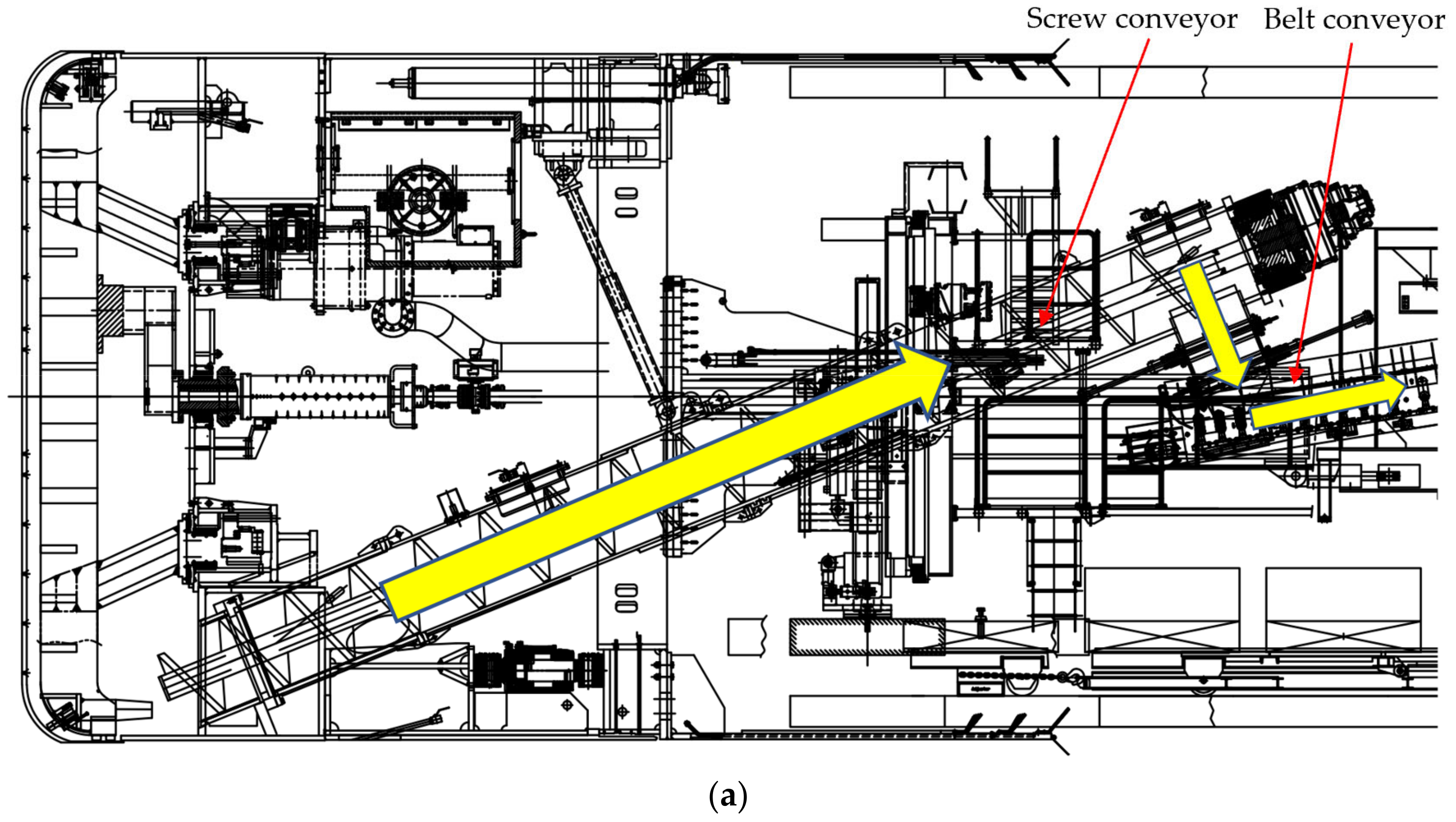
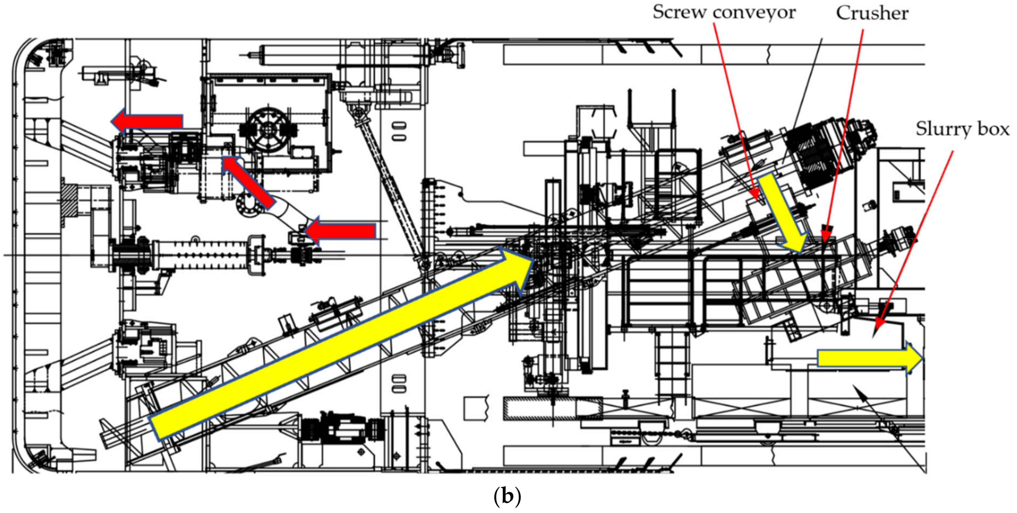
A high construction risk is present because the tunnel needs to pass through many existing buildings in the shield tunneling section. The geology of the section is variable and includes water-rich sandy, argillaceous siltstone, and silty clay strata. Compared with the EPB shield, the slurry shield can better control formation and deformation in water-rich sandy strata. However, the EPB shield has a higher tunneling efficiency in argillaceous siltstone and silty clay strata. Thus, a slurry–earth pressure balance dual-mode shield was selected for tunneling to improve the adaptability of the shield machine. The slurry discharge pipe and the screw conveyor are connected in series. The machine has no bubble chamber. When the EPB mode is adopted for tunneling, a belt conveyor is arranged at the outlet of the screw conveyor to transport the muck directly (Figure 2a). When the slurry mode is adopted, a crusher and slurry box are installed at the outlet of the screw conveyor. The function of the crusher is to crush large stones. The slurry in the shield chamber enters the slurry discharge pipe after passing through the screw conveyor, crusher, and mud box (Figure 2b) and finally flows into the slurry treatment station.
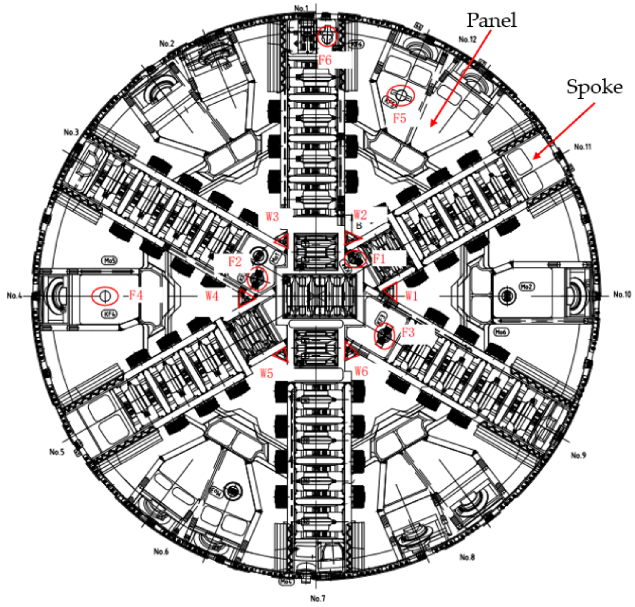
The cutterhead adopts a composite structure of 6 spokes and 6 panels, with an excavation diameter of 6700 mm and an opening ratio of 32% (Figure 3). The cutterhead is equipped with 6 foam injection ports (F1~F6) to condition the soil in the central area. Each pipeline is designed with a single pump to avoid pipe clogging. The cutterhead center is also equipped with 6 high-pressure water injection nozzles (W1~W6).

3. Analysis of the Formation and Cause of Shield Clogging

3.1. Variation in the Tunneling Parameters during the Formation of Shield Clogging

The shield would continuously pass through three buildings after tunneling through the 10th ring. The tunnel is located in the composed stratum with medium–coarse sand in the upper part and weathered argillaceous siltstone in the lower part. When the shield tunneling occurs in this composed stratum, the tunnel face easily loses stability, further causing the surface buildings to crack. Compared with the EPB mode, the slurry mode can better balance the water and soil pressure at the working face. Thus, the slurry mode was used at the start of the shield tunneling section to control the surface settlement and ensure the safety of the surface buildings.
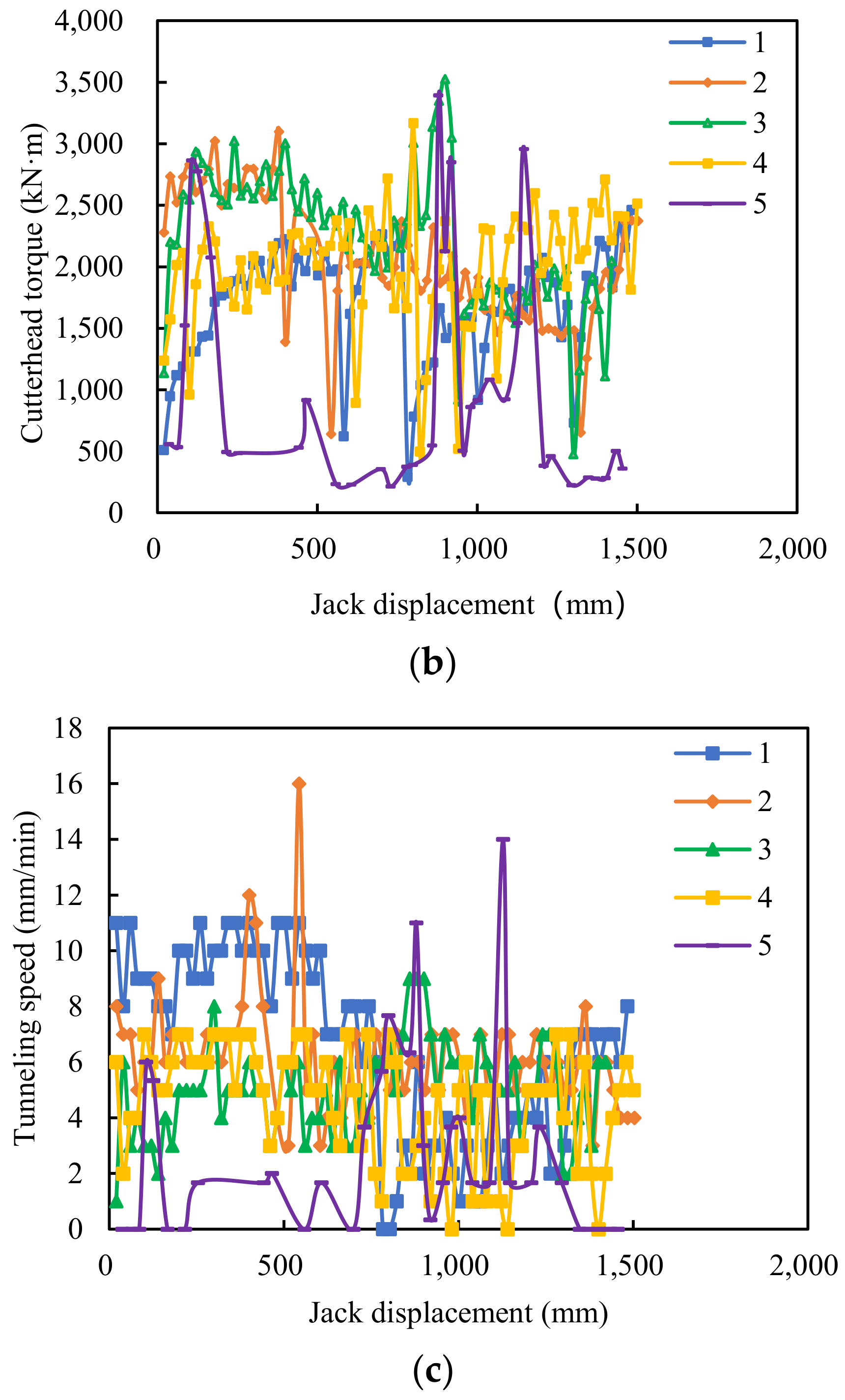
The total thrust force, cutterhead torque, and tunneling speed from the 1st to the 5th ring are shown in Figure 4. The total thrust force of the shield in the 1st~3rd ring and the first 500 mm of the 4th ring had little difference and fluctuated in the range of 8000~18,000 kN. However, the total thrust force gradually increased during the subsequent tunneling of the 4th ring. The cutterhead torque also showed a similar changing trend. The cutterhead torque was approximate in the 1st~3rd ring and the first 500 mm of the 4th ring, while the fluctuation in the cutterhead torque increased significantly during the subsequent tunneling of the 4th ring. The tunneling speed was low and decreased as the ring number increased. When tunneling to the 5th ring, the tunneling speed was approximately 0. The shield tunneling stopped, and the slurry circulation continued. A gap existed between the cutterhead and the tunnel face as the tunnel face was partially emptied during the slurry circulation. Thus, the total thrust force and cutterhead torque of the shield were low, while the tunneling speed was high at the initial stage of tunneling. However, the total thrust force and the cutterhead torque increased significantly, and the tunneling speed subsequently decreased. Thus, the shield was clogged at this time. Then, the slurry level in the chamber was lowered. The clogging of the cutterhead was observed by the visualization system inside the chamber. The results showed that the opening of the cutterhead was basically clogged (Figure 5). The area marked by circle in the figure is the clogged soil.

3.2. Causal Analysis of Shield Clogging

Figure 6 shows a typical geological section of the 1st~15th ring. The tunnel was located in the composed stratum, consisting of medium–coarse sand, silty clay, and weathered argillaceous siltstone. The adhesion of the silty clay and argillaceous siltstone was high. The slurry flow rate in the screw conveyor was low, approximately 0.3 m/s, during the shield tunneling. In addition, the screw conveyor had an inclination of 22°. Thus, it was difficult to transport the adhesive soil from the chamber only by the slurry circulation. Small pieces of soil and clay mass in the slurry formed a soil skeleton in the chamber. Several slurry flow channels existed in the soil skeleton. The slurry circulated normally, but the flowing slurry could not transport the soil. The excavated soil accumulated in the slurry chamber. The accumulated soil prevented the excavated soil from entering the slurry chamber. Finally, the excavated soil accumulated in the cutterhead, and the opening of the cutterhead was clogged. Thus, the total thrust force of the shield increased significantly, the tunneling speed gradually decreased to 0, and the torque of the cutterhead increased.

4. Ideal Soil Consistency Index for the Prevention of Shield Clogging

Field practice showed that the shield was very easy to be clogged when the tunneling was in the slurry mode, which severely affected the construction efficiency. Thus, the EPB mode was subsequently adopted to improve the tunneling efficiency. Soil conditioning was used to prevent shield clogging.
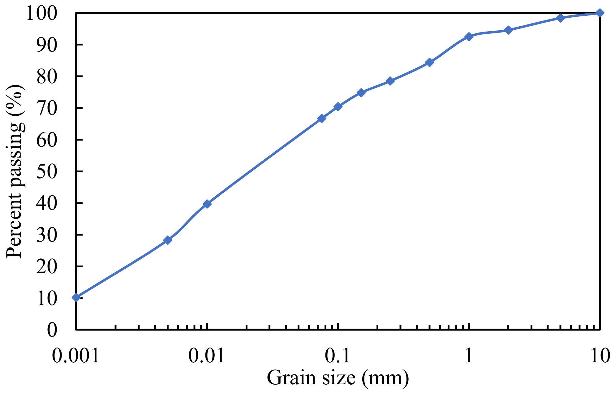
Soil softness is one of the main factors affecting shield clogging. However, because the Atterberg limits are different, the soil softness is not always identical even though the water content of the soil specimens is the same. Thus, the consistency index is used to characterize the soil softness. The consistency index of the soil in the shield chamber should be less than 0.5 to prevent shield clogging [13,14,16]. The consistency index was determined by the Atterberg limits and water content. However, the Atterberg limits are applicable only to soils with particles less than 0.5 mm in diameter and are not suitable for soils with larger particles. The maximum particle size of the soil discharged by the screw conveyor was approximately 10 mm (Figure 7). The consistency index could not be used to characterize the softness of the soil.
The adhesion of the fine particles was strong, while the coarse particles had little adhesion. There exists a critical particle size of soil grains below which soil clogging probably occurs. Wang et al. [10] proposed that the critical particle size of soil grains was 0.15 mm. Fine particles smaller than 0.15 mm were the main cause of the shield clogging. Therefore, it was only necessary to ensure that the consistency index of fine particles less than 0.15 mm in the soil was less than 0.5 to obtain an ideal soil softness. The coarse and fine particles in the soil were mixed. The particles larger than 0.15 mm had also absorbed water due to the internal pores of the particles. It is necessary to remove the water absorbed by particles larger than 0.15 mm when determining the consistency index of particles smaller than 0.15 mm. According to the concrete industry standard, water absorption was used to characterize the water absorption capacity of particles [19,20,21].
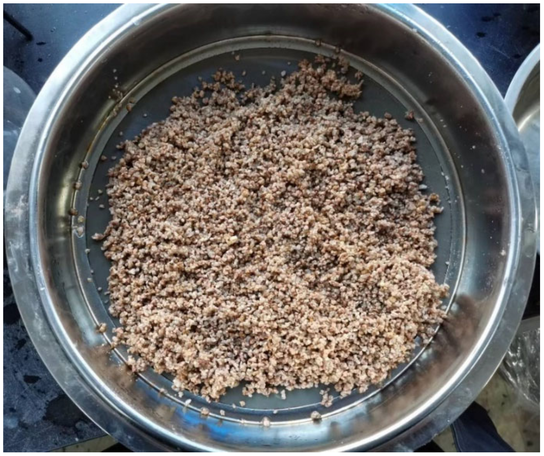
The water absorption test method for soil particles larger than 2 mm was as follows [21]. The specimen was placed in a basin containing water. The water surface was approximately 5 mm higher than the specimen surface. The specimen was removed after soaking for 24 h. The water on the particle surface was wiped with a wrung wet towel (Figure 8). Then, the water content of the specimen, i.e., the water absorption of the soil particles, was measured immediately.
The water absorption test method for the 0.15~2 mm soil particles is as follows:
(1)
The specimen was placed into a shallow container with clean water. The water surface was approximately 20 mm higher than the specimen surface. Then, the mixture of the water and soil particles was stirred with a glass rod for 5 min to eliminate bubbles and covered for 24 h until complete wetting occurred.
(2)
The water on top of the specimen was poured out. A straw was used to remove the residual water from the specimen.
(3)
The specimen was spread in a pan. Then, the specimen was blown with warm air from a portable hair dryer and mixed continuously so that the water in the particle surface group evaporated to reach the estimated soil specimen state. The fine powder was not lost during the blowing.
(4)
The specimen was loosely placed into the test mold simultaneously. The upper and lower diameters of the conical test mold were 40 and 90 mm, respectively. The height was 75 mm. Then, the specimen was tamped 25 times with a tamping rod. The distance between the end of the tamping rod and the surface of the specimen should not exceed 10 mm so that it can fall freely. The mold opening was scraped after the tamping. It was unnecessary to refill the mold if a gap was present.
(5)
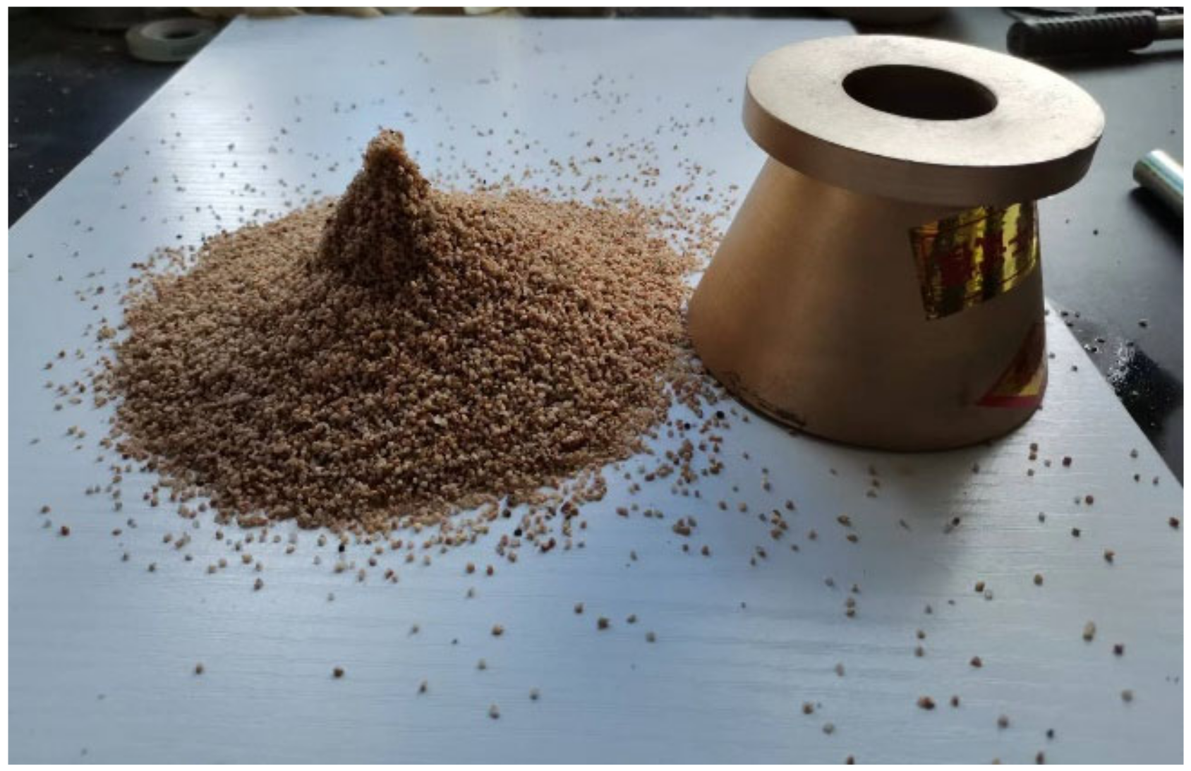
The test mold was lifted slowly in the vertical direction. If the specimen did not collapse, the soil specimen still contained surface water. Then, the soil was dried with warm air according to the above method until the specimen started to fall. If the specimen slumped too much after the test mold was lifted, then the specimen had been overly dried. At this time, the specimen was evenly sprinkled with approximately 5 mL of water, fully mixed, and placed in a covered container for 30 min. Then, it was tested according to the above method until it reached the required state. The required state was that one-third of the specimen slumped (Figure 9).
(6)
After the completion of the slump test, a specimen of not less than 20 g was immediately taken to determine its water content, that is, the water absorption of the specimen.
The water absorption of the coarse particles was first measured according to the relevant specifications. Then, the water absorbed by particles larger than 0.15 mm was deducted. The consistency index of the remaining soil was still less than 0.5 at this time. The soil softness was in an ideal state, which prevented the shield from clogging.

5. Soil Conditioning and Variation in the Tunneling Parameters

5.1. Determination of the Type of Soil Conditioner

A dispersive foam agent is used to condition the cohesive soil. The effective components of the dispersive foam agent are dispersants and surfactants. The role of the dispersant is to disperse the cohesive particles and reduce the adhesion of the soil to the cutterhead, cutter, and bulkhead of the chamber. The role of the surfactant is to reduce the surface tension of the water and produce foam after mixing with air. The dispersant can enhance the negative charge of clay particles, release the bound water between clay particles, and reduce the liquid limit of the residue. Thus, the liquid limit reduction in the soil can be used to evaluate the effect of dispersants [22]. The performance of the foam agent mainly includes the foaming performance and stability. The evaluation indexes are the foam expansion ratio (FER) and half-life [23,24].
(1)
Evaluation of the dispersant performance of soil conditioners
The critical particle size of the soil with clogging potential in the shield tunneling was 0.15 mm [10]. Particles less than 0.15 mm in the soil are the main reason for shield clogging. Thus, the dispersion performance of the soil conditioners can be evaluated by determining the variation in the liquid limit of particles less than 0.15 mm in the soil. The test was carried out step by step as follows. The soil was placed in an oven at 105 °C for at least 24 h. Then, the dried soil was crushed by using rubber. The crushed soil was passed through a 0.15 mm sieve. Particles less than 0.15 mm were collected for the liquid limit test. The liquid limit was determined by the fall cone method according to Chinese standards [17].
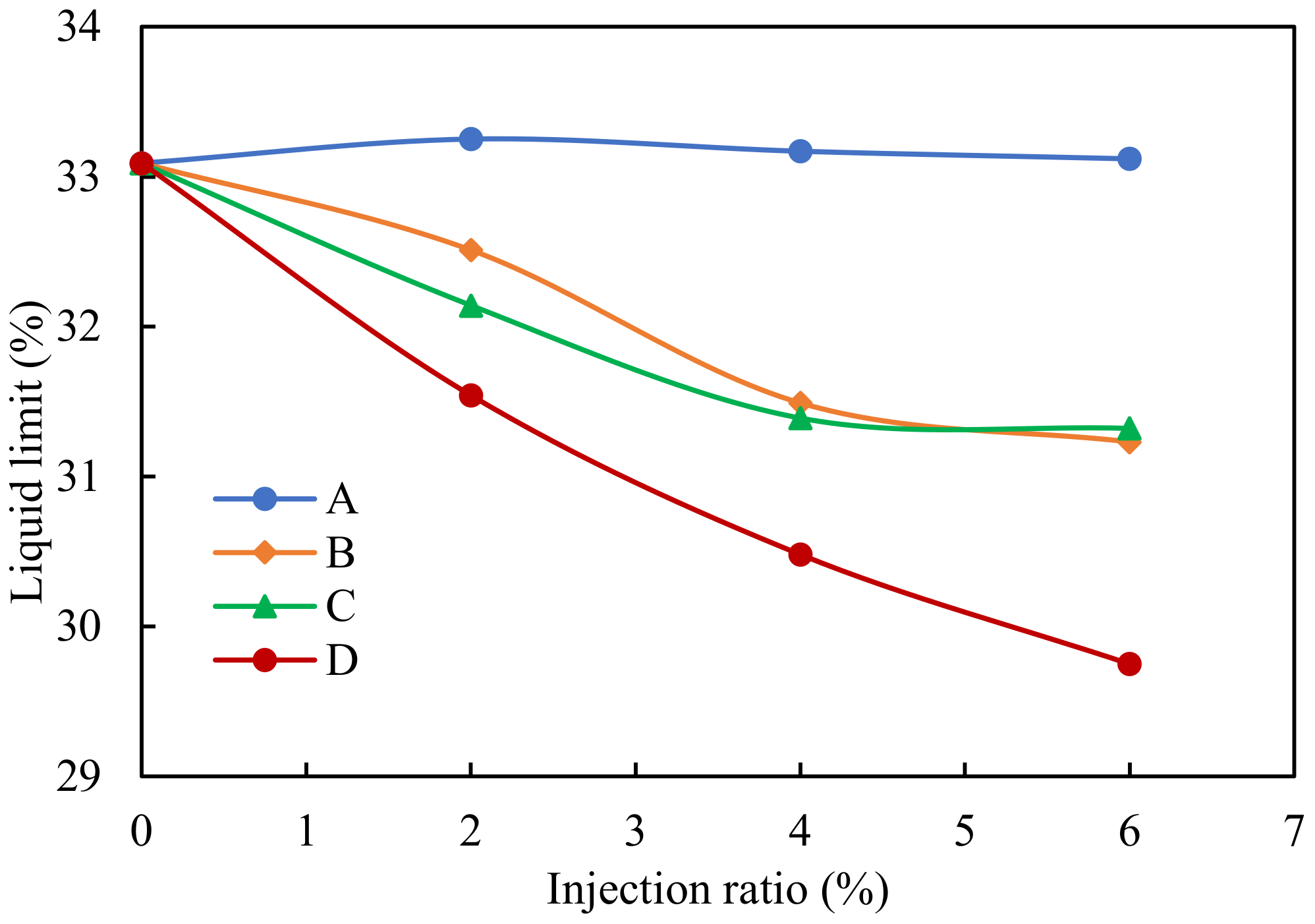
Four foam agents, namely A, B, C, and D, were selected for testing. The injection ratios of the soil conditioner, i.e., the mass ratio of the soil conditioner to the dry soil, were 2%, 4%, and 6%, respectively. Figure 10 shows the variation in the liquid limit with the injection ratio of the foam agents. The liquid limit of the soil specimen remained constant after adding foam agent A, which indicated that the dispersing effect of foam agent A on the soil specimens was poor. After adding foam agents B or C, the liquid limit of the soil specimen decreased with an increase in the injection ratio of less than 4%. The liquid limit did not change obviously when the injection ratio was greater than 4%, which indicated that the effect of the soil conditioner remained almost constant. The liquid limit of the soil specimen gradually decreased with an increase in the injection ratio after adding foam agent D. The liquid limit reduction in the soil specimen with foam agent D was the maximum at the same injection ratio, which indicated that the dispersion effect of foam agent D was the best. Therefore, foam agent D was selected as the soil conditioner for the project.
(2)
Evaluation of the foaming performance of the foam agent
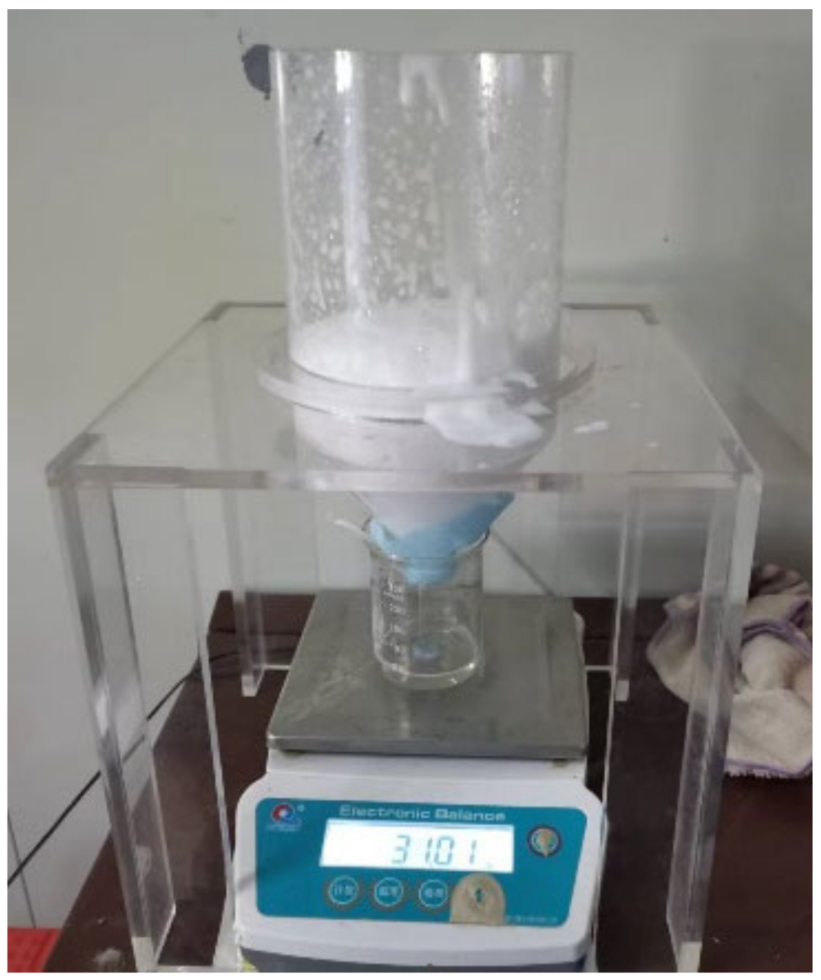
The foam properties varied with the foam concentration. To determine the optimal concentration of the foam agent, the foam generator shown in Figure 11 was used to generate the foam. The compressed air generated by the air compressor was passed into the liquid storage tank containing the foam solution. After the air and foam solution were mixed, the foam was obtained at the air outlet. The foam was put into the measuring cylinder. The foam expansion ratio was determined by calculating the volume ratio before and after the foam dissipation. Figure 12 shows the foam stability test device. The device contains a self-made funnel, a bracket, a beaker, and an electronic scale. The dispersed foam agent solution flowed into the beaker along the container. The reading on the electronic scale gradually increased as the foam burst. The dissipation curve and the half-life of the foam were obtained by recording the readings of the electronic scale at different times.
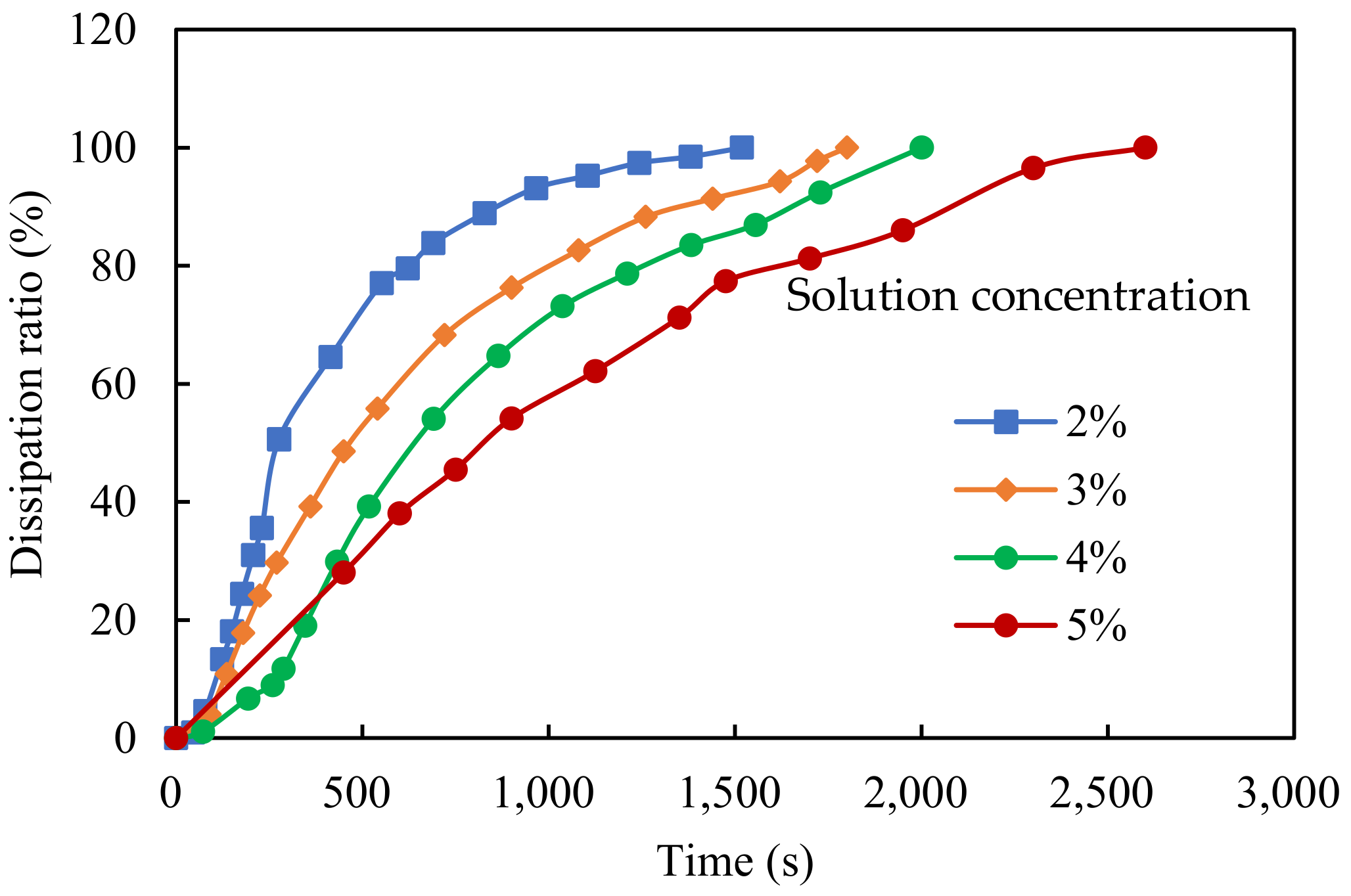
The concentrations of the foaming agent solution were 2%, 3%, 4%, and 5%. When the concentrations of the foam agent solution were 2%, 3%, 4%, and 5%, the foam expansion ratios were 8, 12, 15, and 17, respectively. Figure 13 shows the foam dissipation curves. The dissipation rate of the foam was fast at first and then gradually slowed. The half-lives of the foam produced by the foam agent solutions with concentrations of 2%, 3%, 4%, and 5% were 275 s, 468 s, 644 s, and 828 s, respectively. It is generally required that the foam expansion ratio of foam should not be less than 10 and that the half-life should not be less than 300 s [7,25]. The foam solution with a concentration of 2% did not meet the requirements. The concentration of the foam solution used in the shield tunneling was generally set at 3%. When the soil adhesion was high and the effect of the soil conditioning was not ideal, the concentration of the foam solution appropriately increased to 4~5%.

5.2. Engineering Application and Analysis of Soil Conditioning

(1)
Soil softness control
Foam and water were used to condition the soil. The soil on the belt conveyor was used as the test specimen during the shield tunneling. A small amount of soil was used to determine the water content of the specimen. The rest of the soil was dried at 105 °C for 24 h and crushed by a rubber hammer. Then, the crushed soil passed through 0.15 mm and 2 mm sieves to determine the proportion of particles smaller than 0.15 mm, from 0.15 to 2 mm, and larger than 2 mm in the soil. The Atterberg limits of the soil with particle sizes less than 0.15 mm were determined. The water absorptions of the particles with sizes of 0.15~2 mm and larger than 2 mm were measured. The consistency index of soil with particle sizes less than 0.15 mm was calculated. Table 2 shows the test results. As the stratum of the 1st to 70th ring was changeable (Figure 1), the proportion of the components with sizes less than 0.15 mm, from 0.15 to 2 mm, and greater than 2 mm in the soil varied constantly during the excavation of each ring. The consistency index of soil with particle sizes less than 0.15 mm in the soil was basically less than 0.5 by controlling the injection amount of the foam and water in front of the cutterhead, which was the ideal state to prevent shield clogging.
(2)
Variation in the tunneling parameters
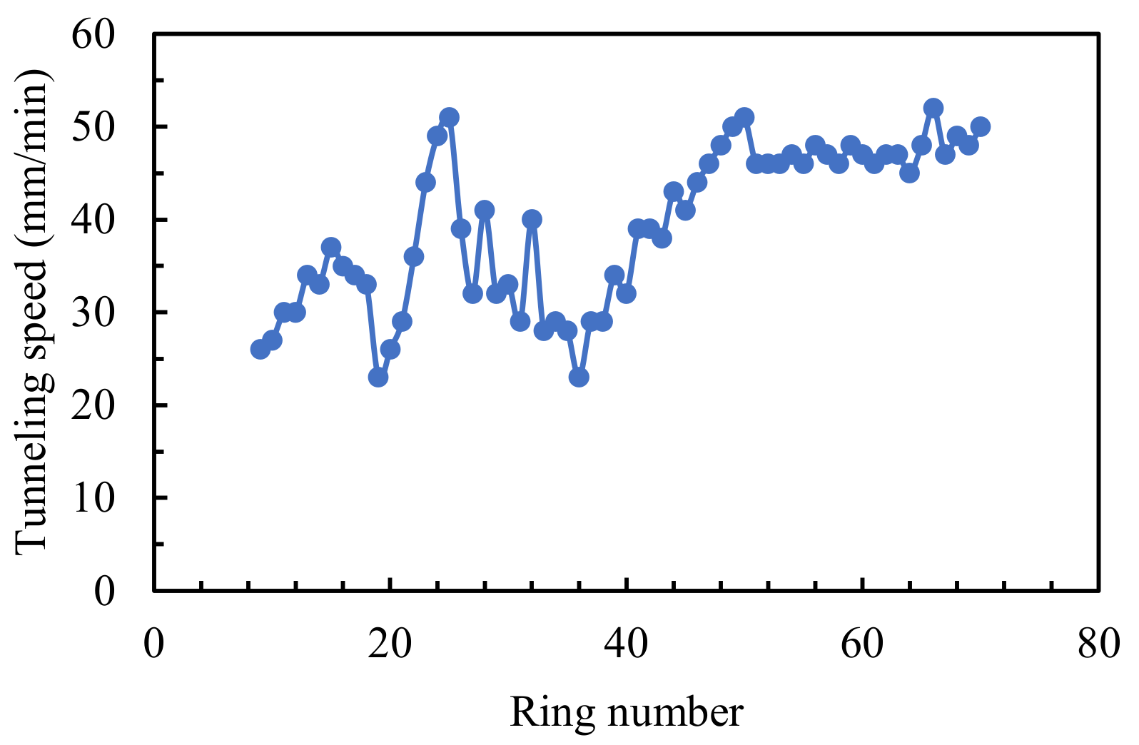
Figure 14 and Figure 15 show the variation in the cutterhead torque, the total thrust force, and the tunneling speed. The total thrust force was in the range of 12,000~20,000 kN. The cutterhead torque values ranged from 1200 to 3500 kN·m. The tunneling speed was in the range of 23~52 mm/min. Compared to Figure 4, the total thrust force and the cutterhead torque decreased while the tunneling speed increased. This result wholly indicated that the soil conditioning had achieved the expected effect.

6. Conclusions

Based on the shield tunnel project of Guangzhou Metro Line 12 in China, the applicability of a slurry–earth pressure balance dual-mode shield was investigated in a composed stratum with medium–coarse sand and argillaceous siltstone. Then, the soil conditioning was studied for the high-adhesion stratum to prevent shield clogging. The main conclusions are described as follows:
(1)
The slurry mode of the slurry–earth pressure balance dual-mode shield was not applicable to the composed stratum with medium–coarse sand and argillaceous siltstone. It was difficult to transport the adhesive soil from the chamber only by the slurry circulation. The excavated soil accumulated in the slurry chamber. The accumulated soil prevented the excavated soil from entering the slurry chamber. Finally, the excavated soil accumulated in the cutterhead, and the opening of the cutterhead was clogged.
(2)
The total thrust force of the shield increased significantly, the tunneling speed gradually decreased to 0, and the torque of the cutterhead increased slightly after the slurry–earth pressure dual-mode balance shield machine in the slurry mode was clogged. The fluctuations in the total thrust force, cutterhead torque, and tunneling speed also increased significantly.
(3)
The EPB mode is recommended for the composed strata with medium–coarse sand and argillaceous siltstone. The dispersible foam agent and water can be used to condition the soil. The type of dispersible foam agent was determined by measuring the effect of the soil conditioner on the liquid limit of the particles with sizes less than 0.15 mm in the soil. The concentration of the foam agent was determined by measuring the half-life and foam expansion ratio of the foam. The injection amount of the foam and water was determined according to the status of the mud discharged by the screw conveyor.
(4)
Water absorption can be used to characterize the water absorption capacity of particles larger than 0.15 mm. The ideal soil state was that the consistency index of the particles smaller than 0.15 mm was less than 0.5 to prevent the EPB shield from clogging. The water absorption of soil with a particle larger than 0.15 mm should be removed when calculating the consistency index.

Author Contributions

Conceptualization, Z.Y. and P.L.; methodology, Z.Y.; software, P.C.; validation, P.L. and S.L.; formal analysis, P.C.; investigation, P.C.; resources, F.J.; data curation, F.J.; writing—original draft preparation, P.L.; writing—review and editing, S.L.; visualization, F.J.; supervision, P.C.; project administration, F.J.; funding acquisition, P.L. All authors have read and agreed to the published version of the manuscript.

Funding

The financial support from the China Postdoctoral Science Foundation (Grant No. 2022M723536) is acknowledged and appreciated.

Institutional Review Board Statement

Not applicable.

Informed Consent Statement

Not applicable.

Data Availability Statement

Not applicable.

Acknowledgments

The authors are also grateful to the help from Shihong Zhai, Xiaofeng Tan, Guanjun You, Haijiang Xu, Gang Li, Xiong He, Qing Yang, Heng Sun, Chao Xu, Zhiyong Yang, and Jun Yu in the CCCC Second Harbor Engineering Company Ltd.

Conflicts of Interest

The authors declare no conflict of interest.

References

  1. Wang, S.; Liu, P.; Gong, Z.; Yang, P. Auxiliary air pressure balance mode for EPB shield tunneling in water-rich gravelly sand strata: Feasibility and soil conditioning. Case Stud. Constr. Mater. 2021, 16, e00799. [Google Scholar] [CrossRef]
  2. Li, X.; Yang, Y.; Li, X.; Liu, H. Criteria for Cutting Head Clogging Occurrence during Slurry Shield Tunneling. Appl. Sci. 2022, 12, 1001. [Google Scholar] [CrossRef]
  3. Wang, Z.; Guo, B.; Wei, G.; Yao, D.; Hu, C. Study for Longitudinal Deformation of Shield Tunnel in Side of Foundation Pit Based on Virtual Image Technique. Appl. Sci. 2022, 12, 8745. [Google Scholar] [CrossRef]
  4. Zumsteg, R.; Langmaack, L. Mechanized Tunneling in Soft Soils: Choice of Excavation Mode and Application of Soil-Conditioning Additives in Glacial Deposits. Engineering 2017, 3, 863–870. [Google Scholar] [CrossRef]
  5. EFNARC. Specification and Guidelines for the Use of Specialist Products for Soft Ground Tunnelling; European Federation for Specialist Construction Chemicals and Concrete Systems: Surry, UK, 2005. [Google Scholar]
  6. Wang, S.; Fu, J.; Zhang, C.; Yang, J. Shield Tunnel Engineering: From Theory to Practice; Central South University Press: Changsha, China, 2021. [Google Scholar]
  7. Maidl, B.; Herrenknecht, M.; Maidl, U.; Wehrmeyer, G. Mechanised Shield Tunnelling; Wiley: Hoboken, NJ, USA, 2012. [Google Scholar]
  8. Thewes, M.; Hollmann, F. Assessment of clay soils and clay-rich rock for clogging of TBMs. Tunn. Undergr. Space Technol. 2016, 57, 122–128. [Google Scholar] [CrossRef]
  9. Ye, X.; Wang, S.; Yang, J.; Sheng, D.; Xiao, C. Soil Conditioning for EPB Shield Tunneling in Argillaceous Siltstone with High Content of Clay Minerals: Case Study. Int. J. Géomeéch. 2017, 17, 05016002. [Google Scholar] [CrossRef]
  10. Wang, S.; Zhou, Z.; Liu, P.; Yang, Z.; Pan, Q.; Chen, W. On the critical particle size of soil with clogging potential in shield tunneling. J. Rock Mech. Geotech. Eng. 2022, in press. [Google Scholar] [CrossRef]
  11. Zumsteg, R.; Puzrin, A. Stickiness and adhesion of conditioned clay pastes. Tunn. Undergr. Space Technol. 2012, 31, 86–96. [Google Scholar] [CrossRef]
  12. Zumsteg, R.; Puzrin, A.; Anagnostou, G. Effects of slurry on stickiness of excavated clays and clogging of equipment in fluid supported excavations. Tunn. Undergr. Space Technol. 2016, 58, 197–208. [Google Scholar] [CrossRef]
  13. Oliveira, D.; Thewes, M.; Diederichs, M.S.; Langmaack, L. EPB tunnelling through clay-sand mixed soils: Pro-posed methodology for clogging evaluation. Geomech. Tunn. 2018, 11, 375–387. [Google Scholar] [CrossRef]
  14. Hollmann, F.S.; Thewes, M. Assessment method for clay clogging and disintegration of fines in mechanised tunnelling. Tunelling Undergr. Space Technol. 2013, 37, 96–106. [Google Scholar] [CrossRef]
  15. Liu, P.; Wang, S.; Shi, Y.; Yang, J.; Fu, J.; Yang, F. Tangential Adhesion Strength between Clay and Steel for Various Soil Softnesses. J. Mater. Civ. Eng. 2019, 31, 04019048. [Google Scholar] [CrossRef]
  16. Wang, S.; Liu, P.; Hu, Q.; Zhong, J. Effect of dispersant on the tangential adhesion strength between clay and metal for EPB shield tunnelling. Tunn. Undergr. Space Technol. 2020, 95, 103144. [Google Scholar] [CrossRef]
  17. GB/T 50123–2019; Standards for Geotechnical Test Methods. China Planning Press: Beijing, China, 2019. (In Chinese)
  18. ASTM D4318-10; Standard Test Method for Liquid Limit, Plastic Limit, and Plasticity Index of Soils. ASTM International: West Conshohocken, PA, USA, 2010.
  19. ASTM C128-12; Standard Test Method for Density, Relative Density (Specific Gravity), and Absorption of Fine Aggregate. ASTM International: West Conshohocken, PA, USA, 2012.
  20. AASHTO T84-13; Standard Method of Test for Specific Gravity and Absorption of Fine Aggregate. American Association of State Highway and Transportation Officials: Washington, DC, USA, 2015.
  21. JTG E42-2005; Test Method of Aggregate for Highway Engineering. China Communications Press: Beijing, China, 2005. (In Chinese)
  22. Liu, P.; Wang, S.; Ge, L.; Thewes, M.; Yang, J.; Xia, Y. Changes of Atterberg limits and electrochemical behaviors of clays with dispersants as conditioning agents for EPB shield tunnelling. Tunn. Undergr. Space Technol. 2018, 73, 244–251. [Google Scholar] [CrossRef]
  23. Quebaud, S.; Sibai, M.; Henry, J.-P. Use of chemical foam for improvements in drilling by earth-pressure balanced shields in granular soils. Tunn. Undergr. Space Technol. 1998, 13, 173–180. [Google Scholar] [CrossRef]
  24. Budach, C.; Thewes, M. Application ranges of EPB shields in coarse ground based on laboratory research. Tunn. Undergr. Space Technol. 2015, 50, 296–304. [Google Scholar] [CrossRef]
  25. Yan, X.; Gong, Q.; Jiang, H. Soil conditioning for Earth Pressure Balanced Shield Excavation in Sand Layer. Chin. J. Undergr. Space Eng. 2010, 6, 449–453. (In Chinese) [Google Scholar]
Figure 1. Geological profile along the shield tunneling section.
Applsci 13 02023 g001
Figure 2. Schematic diagram of the shield tunneling mode; (a) EPB mode; (b) Slurry mode.
Applsci 13 02023 g002aApplsci 13 02023 g002b
Figure 3. Structure diagram of the cutterhead. F1~F6 were foam injection ports. W1~W6 were high-pressure water injection nozzles.
Applsci 13 02023 g003
Figure 4. Variation in the tunneling parameters with jack displacement; (a) Variation in the total thrust force with jack displacement. (b) Variation in the cutterhead torque with jack displacement. (c) Variation in the tunneling speed with jack displacement.
Applsci 13 02023 g004aApplsci 13 02023 g004b
Figure 5. Soil clogging in the chamber.
Applsci 13 02023 g005
Figure 6. Typical geological section of the 1st to the 15th ring.
Applsci 13 02023 g006
Figure 7. Gradation curve of the excavated soil.
Applsci 13 02023 g007
Figure 8. Determination of the water absorption of particles larger than 2 mm.
Applsci 13 02023 g008
Figure 9. Determination of the water absorption of particles with sizes of 0.15~2 mm.
Applsci 13 02023 g009
Figure 10. Variation in the liquid limit with the injection ratio.
Applsci 13 02023 g010
Figure 11. Schematic diagram of the foam generator.
Applsci 13 02023 g011
Figure 12. Foam stability test device.
Applsci 13 02023 g012
Figure 13. Dissipation curves of foam with different concentrations.
Applsci 13 02023 g013
Figure 14. Variation in the total thrust force and cutterhead torque.
Applsci 13 02023 g014
Figure 15. Variation in the tunneling speed.
Applsci 13 02023 g015
Table 1. Physical and mechanical parameters of each stratum.
Geotechnical NameNatural Water Content (%)Quick ShearContent of Silty and Clay Particle (%)Content of Sand (%)
Cohesion Force (kPa)Internal Friction Angle (°)0.005~0.075 mm<0.005 mm0.5~2 mm0.25~0.5 mm0.075~0.25 mm
Silty clay26.8231837.620.89.812.619.2
Medium–coarse sand33.8/32.025.41.122.124.312.7
Completely weathered argillaceous siltstone19.630.2521.542.022.49.010.613.9
Strongly weathered argillaceous siltstone17.036.524.042.220.510.112.812.9
Moderately weathered argillaceous siltstone/10035/////
Table 2. The test result of soil.
Ring NumberWater Content (%)Atterberg Limits of Soil Less than 0.15 mm (%)Water Absorption (%)Proportion of Different Particles (%)Consistency Index of Soil Less than 0.15 mm
Plastic LimitLiquid Limit0.15~2 mm>2 mm<0.15 mm0.15~2 mm>2 mm
934.715.6833.0918.95.773.822.53.70.14
1034.814.2732.7821.74.565.525.88.70.17
1438.116.7135.7217.96.479.817.92.30.04
3127.415.0433.1420.85.161.320.7180.50
5132.414.2334.1417.94.750.230.419.40.31
7029.314.5232.1418.25.459.731.68.70.46
Disclaimer/Publisher’s Note: The statements, opinions and data contained in all publications are solely those of the individual author(s) and contributor(s) and not of MDPI and/or the editor(s). MDPI and/or the editor(s) disclaim responsibility for any injury to people or property resulting from any ideas, methods, instructions or products referred to in the content.