Abstract
Intelligent lower-limb prostheses aims to make amputees walk more comfortably and symmetrically which requires the dynamic altering of gait parameters such as walking speed. Some solutions have been proposed such as direct integration and machine learning methods. The former updates walking speed once after an entire gait cycle and the latter collects large amounts of gait data which are unfriendly to lower-limb amputees. Only by using an inertial measurement unit (IMU) placed on the thigh, this paper proposes a novel online walking speed estimation method to determine the walking speed rapidly and accurately in real-time. A step frequency estimator based on the phase variable and a stride estimator based on the inverted pendulum model is designed to determine the walking speed together. The proposed method is evaluated on a public open-source dataset and the gait data were collected in the lab to verify the effectiveness for able-bodied and prosthetic wearers. The experiment results show that the walking speed estimator offers higher accuracy (RMSE of the able-bodied dataset: 0.051 ± 0.016 m/s, RMSE of the prosthetic wearers‘ dataset: 0.036 ± 0.021 m/s) than the previous works with a real-time frequency of 100 Hz. The results also show that the proposed method has good performances both in static speeds and dynamic speed tracking without much data collection before being applied.
1. Introduction
Lower-limb losses have become a growing global problem. Traffic accidents, wars, sports injuries, burns, complications from diabetes or tumors, and forced amputation are the common reasons for lower-limb losses [1]. In order to help lower-limb amputees restore mobility and return to normal life, scientists have conducted a lot of studies, especially on lower-limb prostheses which are good replacements for amputated parts. At present, most commercially available lower-limb prostheses are passive, because they are relatively cheap, simple in structure and convenient for clinical application. However, walking with passive prostheses will consume 20% to 30% more energy than healthy individuals [2]; the asymmetries between the passive prosthesis and the sound leg will cause back pain, osteoarthritis and osteoporosis [3]; the walking speed may be 10% to 65% slower [1]; mobility in different terrains is limited. Therefore, an intelligent lower-limb prosthesis is worthy of study due to its powerful potential in walking speed selection and adaptation to different terrains.
Scientific researchers have made great progress in intelligent lower-limb prostheses recently including gait planning and control strategies. The common control framework of intelligent lower-limb prostheses is a hierarchical framework. The framework proposed in [4] includes a high-level controller, mid-level controller and low-level controller. The high-level controller focuses on human intention recognition including locomotion mode classification, gait parameter determination, and gait phase determination. The mid-level controller receives the locomotion mode, gait parameters and gait phase and then computes the desired joint torques. Therefore, the gait parameters and gait phase are always related to the joint trajectory generation and controllers. Ref. [5] computes the gait phase by thigh motion; Ref. [6] uses dynamic movement primitives (DMPs) to represent joint motion trajectories and the amplitude parameters of DMPs are the functions of walking speed; Ref. [7] introduces a predictive model that represents gait kinematics as a continuous function of gait cycle percentage, speed, and incline; Ref. [8] applies finite state impedance control (FSIC) which sets different impedance parameters during different gait phases to simulate human joints’ impedance characteristic. To achieve better locomotion mode conversion and dynamic motion, the fast and accurate determination of gait parameters such as walking speed are necessary.
To estimate walking speed, wearable sensors such as inertial measurement units (IMUs) are used in previous works. For now, the walking speed estimation methods can be classified into three kinds: Direct integration method, kinematic model building and machine learning methods. Ref. [9] installs the IMUs on the lower limb and estimates the walking speed by the direct integration method. The potential integral drift problem can be addressed by real-time velocity correction. Ref. [10] applies wearable accelerometers on the wrist and proposes a virtual inverted pendulum model to estimate the walking speed. Ref. [11] develops subject-dependent and independent machine-learning models to determine walking speed. However, methods based on direct integration or kinematic model building only estimate the walking speed once after an entire gait cycle. As for machine learning methods, collecting large amounts of data on lower-limb amputees is unfriendly and the trained regression models or neural networks are not adaptive to amputees’ daily gait changes.
This paper designs a phase-based step frequency estimator and a user-dependent stride estimator to estimate walking speed fast and accurately. Compared to direct integration methods, the proposed method can continuously estimate the walking speed in real-time. Compared to the machine learning methods, the proposed method has no need to collect large amounts of data under different speeds which are friendly to the lower-limb amputees. The novel contributions of this paper are listed below: (1) Based on the phase method [12], the real-time estimation of walking speed is achieved with better accuracy; (2) the proposed method is proved to be effective both in prosthetic wearers and the able-bodied; (3) only one wearable sensor (an IMU placed on the thigh) is used which is accordant with the concept of a lightweight prosthesis; (4) the proposed method shows good performance for static speeds and dynamic speed tracking; (5) the stride estimator can calculate the stride symmetry in real time which can be input to the controller as a performance index to be optimized.
2. Materials and Methods
Walking speed is the product of step frequency and stride, so the online estimation of walking speed is decomposed into the real-time estimation of step frequency and stride . The focus of this section is to demonstrate the step frequency estimator and stride estimator in detail.
2.1. Phase-Based Step Frequency Estimator
Ref. [12] proves that the gait phase can be obtained by thigh motion and Ref. [13] proves that the thigh motion can represent the gait cycle by using a motion capture system. Therefore, an IMU is placed on the right thigh to obtain the thigh angle and thigh angular velocity in the sagittal plane. The gait phase is obtained through data process and filtering which are introduced below.
2.1.1. Gait Phase Variable of Thigh Motion
The gait phase variable is used to represent a complete gait cycle. Here, we intend to compute the gait phase variable by the motion of the right thigh. The sagittal data of the right thigh IMU are collected and the sample period of IMU is . The measured thigh angle and thigh angular velocity are marked as and . The gait phase variable is defined as
The phase scatter diagram is shown in Figure 1 with blue points and the gait phase variable of each point is its polar angle. In order to make the phase variable change continuously on [0, 2π], it is necessary to translate the phase diagram so that it wraps the origin. At the same time, the angle and angular velocity of the right thigh are normalized, respectively, to make the trajectory of the phase diagram closer to a circle [12]. Translation and normalization formulas are as follows
where is the scaling factor, is the normalization coefficient and is the translation coefficient. and are calculated in real-time according to Equation (4) during walking. and are the thigh angle and thigh angular velocity after translation and normalization.
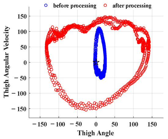
Figure 1.
Phase scatter diagrams of thigh motion and the pentagram represents the origin.
The maximum and minimum values in Equation (4) are calculated in real-time from the data of the previous gait cycle. The phase scatter diagrams before and after processing are shown in Figure 1. After processing, the phase diagram is close to a circle centered on the origin.
The processed gait phase variable is computed as
is the blue dotted line shown in Figure 2. In each gait cycle, the linearity between and time is poor, mainly due to the noises in the measured thigh angle and angular velocity. Here, Kalman filtering is applied to fuse data to remove noise and improve data accuracy. and are the states which are input into the Kalman filtering equation. is computed as
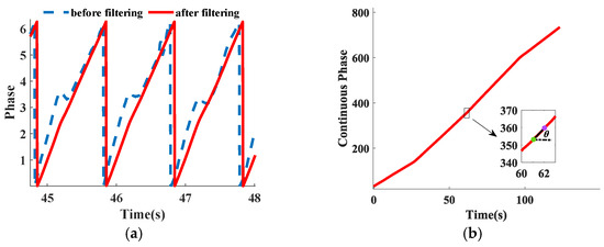
Figure 2.
(a) Phase-time diagram before filtering and after filtering. (b) The y-axis shows the continuous phase and the x-axis is time.
Kalman filtering equation consists of a prediction equation and a correction equation. The system state equation and observation equation are shown in Equation (7). Equation (8) is the covariance prediction equation and Equation (9) is the correction equation.
where is the state, is the state transition matrix, is the observation vector, is the observation matrix, is the covariance matrix of the state, is the covariance matrix of the process noise, is the Kalman gain, is the measured covariance matrix, and is the two-dimensional identity matrix. A good filtering effect has been achieved when the values of and are
The gait phase variable after filtering is shown in Figure 2a. It is found that there is little delay and better linearity after Kalman filtering. The filtered gait phase variable is recorded as .
2.1.2. Real-Time Step Frequency Computation
To make the phase variable of two adjacent gait cycles continuous (calculation of slope requires continuous curve), the continuous gait phase variable is computed through Equation (11).
where is the number of gait cycles that have been passed up to time . The continuous gait phase variable is a continuous and monotonically increasing gait phase variable during walking as shown in Figure 2b. The purple point represents the current time t and the green point represents the time t′. The interval ti = t − t′ = 1 s is given in advance. Two points are connected by a solid line segment and the dotted line is horizontal. The angle between the two lines is marked as .
The continuous gait phase variable is increased by radians after one gait cycle . So, the slope of the continuous gait phase variable in real-time is
The real-time step frequency can be estimated by
2.2. Stride Estimator Based on Inverted Pendulum Model
As shown in Figure 3, a simple inverted pendulum model is built. The rotation angle of the inverted pendulum from the right heel strike to the right foot-flat is and the rotation angle of the inverted pendulum from right foot-flat to right toe off is . When the right leg stands vertically, the right thigh angle in the sagittal plane is 0°; when the right leg swings forward, the right thigh angle in the sagittal plane increases.
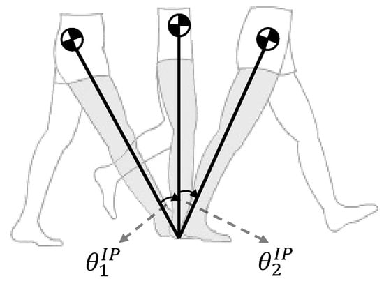
Figure 3.
Inverted pendulum model during walking.
and can be calculated by Equation (14).
The length of the inverted pendulum is marked as which is consistent with the leg length when the human leg is straightened. The stride is the moving distance of the subject’s center of mass (COM) during one gait cycle which can be computed as
So, we can figure out the online walking speed according to Equations (1), (13) and (15)
3. Results
3.1. Data Acquisition
3.1.1. AB (the Able-Bodied) Dataset
The AB dataset comes from the publicly available open-source dataset which is collected by Aaron Young’s team [14]. The AB dataset contains the motion data of 11 able-bodied subjects (AB06–AB16). Among those subjects, there are eight males and three females, aged from 19 to 24 years old, and their heights range from 1.52 m to 1.80 m. Each subject completes eight level walking trials on the treadmill (Figure 4) with different speeds (0.5 m/s, 1.3 m/s, 1.7 m/s and 0.9 m/s). The data of the right thigh IMU are recorded with a sampling frequency of 200 Hz.
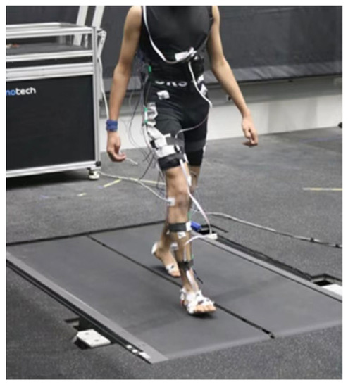
Figure 4.
Experimental setup [14] of AB dataset.
3.1.2. PW (Prosthetic Wearer) Dataset
During PW dataset collection, the subjects are required to wear the intelligent lower-limb prosthesis shown in Figure 5a (a lower-limb prosthesis designed for able-bodied subjects, in which the knee and ankle are active joints that provide power in the sagittal plane) and walk steadily on the treadmill with a slope of 0° (Figure 5b). The prosthesis includes three embedded mechanical sensors: two joint encoders to measure the kinematics of the knee and ankle and one IMU placed on the thigh. All sensor data are collected at 100 Hz. The subjects are required to complete six static speed trials and the walking speeds range from 1.5 km/h to 4.0 km/h with an interval of 0.5 km/h. Time stamps, data of IMU, real-time treadmill speed and joint angles are recorded to form the PW dataset.
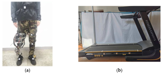
Figure 5.
Experimental equipment. (a) An able-bodied subject wears intelligent lower-limb prostheses and IMUs. (b) The treadmill for level walking.
3.2. Dynamic Speed Tracking Validation
RMSE and time delay are calculated to test the estimation accuracy and determine the response time during speed changes, respectively. The interval has an effect on these two performances. Based on the AB dataset, the dynamic speed tracking performances across different values of the interval are shown in Figure 6.
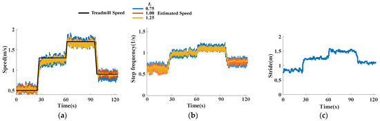
Figure 6.
Experimental results based on the AB dataset. (a) Speed tracking results. (b) Step frequency estimation of AB06. (c) Stride estimation of AB06.
From Figure 6a, the proposed method has a good performance in both static speeds and dynamic speed tracking. The average RMSE across subjects is 0.089 ± 0.014 m/s, 0.051 ± 0.016 m/s and 0.045 ± 0.012 m/s and the average time delays are 389 ms, 553 ms and 678 ms as increases. According to Equations (13) and (15), the step frequency changes and the stride stays unchanged when changes. Moreover, with the change in walking speed, the stride and step frequency increase or decrease at the same time. The time delays are smaller than one gait cycle which shows better responsiveness than traditional methods such as direct integration methods.
During dynamic speed tracking, the RMSE decreases with the speed increasing as shown in Figure 7a. We guess the reason is that it is difficult to keep the step frequency stable at low speeds (from Figure 6b, AB06’s step frequency at lower speeds is more variable).
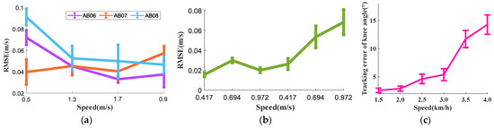
Figure 7.
(a) Speed estimation errors at different speeds based on the AB dataset; (b) Speed estimation errors at different speeds based on the PW dataset. (c) Tracking errors of prosthetic knee angle when subjects are equipped with the lower-limb prosthesis and walk at different speeds. The error band represents one standard deviation.
3.3. Static Speed Tracking of PW Dataset
Based on the PW dataset, the static speed tracking performances are shown in Figure 8. The tracking performances are pretty good when the speed is less than 3 km/h and we can reach the same conclusion from Figure 7b that the RMSE remains almost unchanged at lower speeds but eventually increases. The preliminary guess is that the force acting on the knee joint at heel-strike or toe-off is greater at higher speeds which bring bigger knee angle tracking errors as shown in Figure 7c. Therefore, the deviation between the inverted pendulum model and the actual model increases which leads to a higher estimation error of walking speed. The results indicate that the control performances of intelligent prostheses affect walking speed estimation.
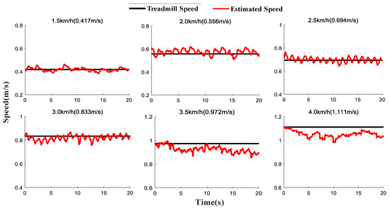
Figure 8.
Experimental results based on the PW dataset.
3.4. Comparison of Previous Works
Based on the AB dataset, the RMSE across 11 subjects of the proposed walking speed estimator is 0.051 ± 0.016 m/s. Based on the PW dataset, the RMSE across six subjects is 0.036 ± 0.021 m/s. The repeated-measures ANOVA (p < 0.05) is used to test the effects of walking speed on the absolute difference between estimated and actual speed estimation error.
Previous works presented lots of methods to estimate walking speed. Sabatini placed an IMU on the foot, and the RMSEs less than 0.05 m/s are obtained for tested speeds and inclines varying in the intervals [3,6] km/h and [5, +15]%, respectively [9]. Boris used a single shank embedded IMU and achieve a mean RMSE of 0.09 m/s for a level walking mission [15]. With analysis of variance (ANOVA), Li computed the estimation errors at different speeds and slopes [16] and Bhakta used machine learning models for both subject-dependent and subject-independent algorithms to estimate walking speed when the speed is lower than 0.9 m/s [11]. Table 1 reports walking speed estimation methods proposed in recent years, as well as the sensors used, number of subjects, statistical analysis methods and experimental results. Through comparison of the listed research works, it can be found that the proposed method in this paper has high accuracy.

Table 1.
Related papers and experimental results of walking speed estimation methods.
4. Discussion
Our study explores the method to estimate two gait parameters of stride and step frequency whose product is exactly the walking speed. Compared to prior literature, this paper achieves higher accuracy. It can be seen that our method contributes to speed switch, gait analysis and more aspects in the discussion below.
4.1. Speed Switch
The desired angles of the knee and ankle which are input into the prosthesis controller are obtained from the natural walking of the able-bodied subjects without wearing a prosthesis on the treadmill. From Figure 9, it is known that the desired angles of the knee and ankle vary with the walking speeds. Therefore, the accuracy estimation of walking speed is helpful to choose the right desired trajectories during the speed switch while there are lots of studies that introduce walking speed into gait planners. For example, ref. [17] uses discrete Fourier transform (DFT) to characterize the desired periodic joint trajectories as functions of the gait phase across the entire stride and extends the control method to different walking speeds; ref. [18] uses the real-time walking speed and gait phase as the inputs into the Gaussian process (GP) functions to specify the desired trajectories and feed-forward torques for the knee and ankle.
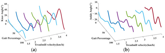
Figure 9.
The desired angles of knee (a) and ankle (b) at different speeds.
If the real-time walking speed is not obtained or misestimated, the wrong desired trajectories will be input into the prosthesis controller which will lead to the reduction in the stride symmetry (for simplicity, stride symmetry is defined as the stride difference between the sound leg and the prosthesis leg). As shown in Figure 10a, the stride of the prosthetic leg and the sound leg is closest under a speed of 3 km/h.
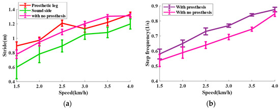
Figure 10.
(a) The results of stride estimator at different speeds. In this experiment, the desired trajectories which is input to prosthesis controller are collected under the speed of 3 km/h. (b) The results of step frequency estimator at different speeds.
To sum up, the accurate estimation of walking speed which is achieved in this paper can contribute to the speed switch during walking by adjusting the desired trajectories of the lower-limb joints, making the gait of the prosthetic wearer more natural and symmetrical.
4.2. Gait Analysis
Under different speeds, the step frequency of one able-bodied subject with or without a prosthesis is measured as shown in Figure 10b. It is found that when the subject walks with a prosthesis the step frequency is higher. Because of the instability the prosthesis brings, the subject accelerates the frequency of adjusting the gait to increase the dynamic stability. However, when the speed is 4 km/h, the step frequencies of both are almost the same because the strides of both are near to upper limit.
The strides of the prosthetic wearer’s sound leg and prosthetic leg are measured as shown in Figure 10a. The figure shows that the stride of the sound leg is smaller than the prosthetic leg under the same speed. We guess that because the subject trusts his sound leg more, he shortens the stride of the sound leg to increase its support time. The difference between the two strides also may come from the mechanical design.
From the above discussion, gait analysis can help make comments and compare the performance of a prosthesis. Moreover, walking speed is used to evaluate impaired mobility [19] and assess the physical condition [20] of amputees.
5. Conclusions
Based on the gait phase and kinematic model, which is commonly used in intelligent lower-limb prostheses, a method to estimate walking speed online is proposed. This paper innovatively designs a step frequency estimator and a stride estimator to estimate the walking speed and only one wearable sensor is used. The experimental results based on a dataset of able-bodied (RMSE: 0.051 ± 0.016 m/s) and prosthetic wearers (RMSE: 0.036 ± 0.021 m/s) show the proposed method is competitive and suitable for static speed estimation and dynamic speed tracking.
In the future, the real-time lower-limb joints’ angles will be considered to correct the inverted pendulum model so as to improve the stride estimation accuracy at high speeds; the stride symmetry can be applied in the control framework as a real-time performance index; moreover, the proposed walking speed estimation method will be extended and tested under different terrains such as ramps and stairs.
Author Contributions
Conceptualization, Y.L. and H.A.; methodology, Y.L. and H.A.; software, Y.L.; validation, Y.L., H.A. and H.M.; formal analysis, Y.L.; data curation, Y.L.; writing—original draft preparation, Y.L.; writing—review and editing, H.A., H.M. and Q.W.; visualization, Y.L.; supervision, H.A., H.M. and Q.W.; project administration, H.A.; funding acquisition, H.A., H.M. and Q.W. All authors have read and agreed to the published version of the manuscript.
Funding
This research was funded by the project of the National Key Research and Development Program of China, grant number (2018YFC2001304).
Informed Consent Statement
Not applicable.
Data Availability Statement
Not applicable.
Conflicts of Interest
The authors declare no conflict of interest.
References
- Asif, M.; Tiwana, M.I.; Khan, U.S.; Qureshi, W.S.; Iqbal, J.; Rashid, N.; Naseer, N. Advancements, Trends and Future Prospects of Lower Limb Prosthesis. IEEE Access 2021, 9, 85956–85977. [Google Scholar] [CrossRef]
- Au, S.K.; Weber, J.; Herr, H. Powered ankle-foot prosthesis improves walking metabolic economy. IEEE Trans. Robot. 2009, 25, 51–66. [Google Scholar] [CrossRef]
- Robert, G.; Kerry, A.; Julie, C.; Jennifer, K.; Mariah, R. Review of secondary physical conditions associated with lower-limb amputation and long-term prosthesis use. J. Rehabil. Res. Dev. 2008, 45, 15–30. [Google Scholar]
- Tucker, M.R.; Olivier, J.; Pagel, A.; Bleuler, H.; Bouri, M.; Lambercy, O. Control strategies for active lower extremity prosthetics and orthotics: A review. J. NeuroEng. Rehabil. 2015, 12, 1. [Google Scholar] [CrossRef] [PubMed]
- Kang, I.; Molinaro, D.D.; Duggal, S.; Chen, Y.; Kunapuli, P.; Young, A.J. Real-Time Gait Phase Estimation for Robotic Hip Exoskeleton Control During Multimodal Locomotion. IEEE Robot. Autom. Lett. 2021, 6, 3491–3497. [Google Scholar] [CrossRef] [PubMed]
- Zhang, G.; An, H.; Liu, Y.; Huang, Y.; Ma, H.; Wei, Q. Phase-based Dynamic Movement Primitives for Powered Knee-Ankle Prosthesis Control. In Proceedings of the 6th International Conference on Robotics and Automation Sciences (ICRAS), Wuhan, China, 25 April 2022. [Google Scholar]
- Embry, K.R.; Villarreal, D.J.; Macaluso, R.L.; Gregg, R.D. Modeling the Kinematics of Human Locomotion over Continuously Varying Speeds and Inclines. IEEE Trans. Neural Syst. Rehabil. Eng. 2018, 26, 2342–2350. [Google Scholar] [CrossRef] [PubMed]
- Lawson, B.E.; Ruhe, B.; Shultz, A.; Goldfarb, M. A Powered Prosthetic Intervention for Bilateral Transfemoral Amputees. IEEE Trans. Biomed. Eng. 2015, 62, 1042–1050. [Google Scholar] [CrossRef] [PubMed]
- Sabatini, A.M.; Martelloni, C.; Scapellato, S.; Cavallo, F. Assessment of walking features from foot inertial sensing. IEEE Trans. Biomed. Eng. 2005, 52, 486–494. [Google Scholar] [CrossRef] [PubMed]
- Hu, J.-S.; Sun, K.-C.; Cheng, C.-Y. A Kinematic Human-Walking Model for the Normal-Gait-Speed Estimation Using Tri-Axial Acceleration Signals at Waist Location. IEEE Trans. Biomed. Eng. 2013, 60, 2271–2279. [Google Scholar] [PubMed]
- Bhakta, K.; Camargo, J.; Compton, W.; Herrin, K.; Young, A. Evaluation of Continuous Walking Speed Determination Algorithms and Embedded Sensors for a Powered Knee & Ankle Prosthesis. IEEE Robot. Autom. Lett. 2021, 6, 4820–4826. [Google Scholar]
- Quintero, D.; Lambert, D.J.; Villarreal, D.J.; Gregg, R.D. Real-Time continuous gait phase and speed estimation from a single sensor. Control Technol. Appl. IEEE 2017, 2017, 847–852. [Google Scholar]
- Villarreal, D.J.; Poonawala, H.A.; Gregg, R.D. A Robust Parameterization of Human Gait Patterns Across Phase-Shifting Perturbations. IEEE Trans. Neural Syst. Rehabil. Eng. 2017, 25, 265–278. [Google Scholar] [CrossRef] [PubMed]
- Camargo, J.; Ramanathan, A.; Flanagan, W.; Young, A. A comprehensive, open-source dataset of lower limb biomechanics in multiple conditions of stairs, ramps, and level-ground ambulation and transitions. J. Biomech. 2021, 119, 110320. [Google Scholar] [CrossRef] [PubMed]
- Dauriac, B.; Bonnet, X.; Pillet, H.; Lavaste, F. Estimation of the walking speed of individuals with transfemoral amputation from a single prosthetic shank-mounted IMU. Proc. Inst. Mech. Eng. Part H J. Eng. Med. 2019, 233, 931–937. [Google Scholar] [CrossRef] [PubMed]
- Li, Q.; Young, M.; Naing, V.; Donelan, J. Walking speed estimation using a shank-mounted inertial measurement unit. J. Biomech. 2010, 43, 1640–1643. [Google Scholar] [CrossRef] [PubMed]
- Quintero, D.; Villarreal, D.J.; Lambert, D.J.; Kapp, S.; Gregg, R.D. Continuous-Phase Control of a Powered Knee–Ankle Prosthesis: Amputee Experiments Across Speeds and Inclines. IEEE Trans. Robot. 2018, 99, 686–701. [Google Scholar] [CrossRef]
- Thatte, N.; Shah, T.; Geyer, H. Robust and Adaptive Lower Limb Prosthesis Stance Control via Extended Kalman Filter-Based Gait Phase Estimation. IEEE Robot. Autom. Lett. 2019, 4, 3129–3136. [Google Scholar] [CrossRef]
- Martin, C.L.; Phillips, B.A.; Kilpatrick, T.J.; Butzkueven, H.; Tubridy, N.; McDonald, E.; Galea, M.P. Gait and balance impairment in early multiple sclerosis in the absence of clinical disability. Mult. Scler. J. 2006, 12, 620–628. [Google Scholar] [CrossRef] [PubMed]
- Waters, R.L.; Mulroy, S. The energy expenditure of normal and pathologic gait. Gait Posture 1999, 9, 231. [Google Scholar] [CrossRef] [PubMed]
Disclaimer/Publisher’s Note: The statements, opinions and data contained in all publications are solely those of the individual author(s) and contributor(s) and not of MDPI and/or the editor(s). MDPI and/or the editor(s) disclaim responsibility for any injury to people or property resulting from any ideas, methods, instructions or products referred to in the content. |
© 2023 by the authors. Licensee MDPI, Basel, Switzerland. This article is an open access article distributed under the terms and conditions of the Creative Commons Attribution (CC BY) license (https://creativecommons.org/licenses/by/4.0/).