Abstract
A total artificial heart (TAH) represents a challenge in medical science to provide a survival perspective for patients with severe cardiac problems. Although cardiac transplantation represents the optimal therapeutic solution for end-stage heart failure, its application is limited by organ shortages. However, innovative technologies that can fit the operation and constraints of a physical heart are now under experimentation, making the target of a reliable and minimally invasive TAH much closer. The electromagnetic devices involved in system supply and actuation could potentially improve patient quality of life and expectancy. The purpose of this paper is to provide an overview of the operating principle, ratings, and key performance of the main electromagnetic components, with a particular focus on actuators that emulate the pumping effect of the heart ventricles. Linear oscillating actuators are very promising for their compactness and straightforward integration; therefore, an exhaustive overview considering both the single and the dual-mover configurations is worth being carried out. Taking a cue on the projects under development and after a detailed literature investigation, the pros and cons of the different solutions are discussed with the purpose of providing a critical analysis of the state-of-the-art.
1. Introduction
In case of severe cardiac problems, the only chance of long-term survival for the patient is to use a total artificial heart (TAH) or a ventricular-assisted device (VAD). VADs help the biological heart by providing mechanical circulatory support that helps the ventricles pump blood, easing the workload of the heart in patients with advanced heart failure. They are durable devices that can assist either one ventricle (left ventricular assist device, LVAD, right ventricular assistant device, RVAD) or both ventricles (biventricular assist device, BiVAD), without explanting the natural heart. Largely diffused in the market, VADs are adopted in most cases as a bridge to transplantation (BTT) for patients who present a cardiogenic shock or have heart failure refractory to medical treatment and whose myocardial function is unlikely to recover. Alternatively, they can be used as destination therapy (DT) for patients who are not eligible for heart transplantation. In this case, it is requested to support the circulation for a period of years, allowing patients to return to their normal activities. In both BTT and DT conditions, they must be lighter and smaller to allow their implantation in as many patients as possible [1,2,3,4].
Instead, the TAH is designed to completely replace an irreversibly damaged heart, provided with an internal actuation system integrated with four artificial valves that reproduce the blood pull-in/pull-out action of the natural ventricles. An auxiliary TAH (ATAH) has been proposed with the purpose to avoid complete heart removal; at the same time, it deals with the size limitation of the thoracic cavity that prevents some patients from receiving TAH or BiVAD devices [5]. The miniaturized configuration required strict design to fulfill both the hydraulic and hemodynamic performances that required further improvements through blood flow studies in the device chambers [6]. Integration with the natural heart to obtain the appropriate blood flow could be another issue.
In addition to fulminant myocardial infarction and dilated or ischemic cardiomyopathy, TAH therapy is currently considered a therapy option in cases of infiltrative cardiomyopathies, transplant failure, and LVAD, as well as complex congenital defects. The device can be implanted inside or outside the patient’s body according to the type of technology, satisfying the physiological and mechanical constraints as accurately as possible. The main ones are [7]:
- Adequate cardiac output generation;
- Adoption of biocompatible and durable materials (the complete system must last more than 5 years);
- Limited heat generation and power consumption;
- Presence of a back-up supply unit whether the main one was not available;
- Balance the systemic and pulmonary circulations despite a wide variety of hemodynamic perturbations;
- Avoid bulky and complex equipment (external driver, percutaneous drivelines, or pneumatic hose) that can limit patient survival and quality of life.
Numerous models of TAHs have been designed and implanted over the years [2,8,9,10,11,12,13]. The SynCardia TAH (SynCardia Systems; Tucson, AZ, USA) was the first TAH to be successfully used in the world. It is a partially implantable system made of two semi-rigid polyurethane ventricles [14,15]. The artificial ventricles are available in two sizes (maximum stroke volume: 70 ml and 50 ml) according to body surface area (BSA) [9]. The AbioCor® TAH (ABIOMED) was the only fully implantable, self-contained TAH to be implanted in humans that used a mechanism to equalize the pulmonary and systemic flow [16,17]. The energy converter is situated between the ventricles and contains a high-efficiency miniature centrifugal pump that operates unidirectionally to pressurize a low-viscosity hydraulic fluid. Although the device was subsequently refined to decrease its overall size, the project was discontinued because it was deemed commercially unviable and prohibitively difficult. The Aeson® CARMAT TAH is an implantable, active electrohydraulic device with a shape close to that of a human heart [18]. It is commercially available in Europe and received FDA approval for use in the US Early Feasibility Study in 2021 [19].
Today, there are few operating units involved in the development and application of such technology, despite the high need. Severe heart disease affects approximately 64 million adults and pediatric patients annually [20]. For example, in Italy, about 1041 new patients entered the transplant list in 2021, and the average attendance is approximately 3.4 years [21]. Recent reports elaborating data from more than a decade evidence some effectiveness of TAH as BTT therapy. Between implanted patients, more than 60% were successfully bridged to transplantation and approximately 80% had one-year of survival after successful BTT [22]. Between adverse pump complications, the failure is rather infrequent due to the quite mature electrical-based technology and the implementation of fault-tolerant designs. The most common complications are patient-related risk factors or issues relating to the pump-patient interface, such as acquired von Willebrand disease, bleeding complications, infection, stroke, and pump thrombosis [1].
It should be noted that actual VADs and TAHs are designed for an adult subject, whereas cardiac issues can arise even at pediatric age. To deal with such issues, the devices should be much lighter and smaller, representing a challenge for many research institutes. A recent study on the available technology for pediatric mechanical circulatory support devices (27 devices among TAHs and VADs were analyzed in detail) showed that still no pediatric pump technology satisfies the unique and distinct design constraints and requirements to support pediatric patients [23].
The purpose of this paper is to provide an overview of the most advanced electromagnetic technologies proposed in the literature for implantable TAHs. First, a detailed description of the main TAH components is provided, considering both energy transmission and electric drive technologies. The latter are analyzed by evaluating the different pumping modes (centrifugal or axial flows) and the bearing system to support the rotor shaft. Then, different types of linear oscillating actuators (LOAs) are presented, examining in detail the configurations applying permanent magnets (PMs), which are among the best candidates to fulfill mandatory constraints on size, weight, and efficiency. The analysis mainly focuses on single-mover configurations, applicable for both VAD and TAH applications, comparing them from an overall perspective including manufacturing, installation, and performance aspects. Yet, preliminary force results related to a dual-mover LOA are reported, which is promising for a fully integrated TAH. Finally, unconventional motor configurations are also described, where challenging features, such as contactless mechanical power transmission and linear rotary actuation, can be implemented.
2. Main TAH Projects
The first experiences focus on fluid-driven (FD) TAHs actuated by pneumatic or hydraulic devices with external drivers. Figure 1a sketches a typical arrangement where the pump injects the fluid by an alternate rotating motion that is consistent with the filling and ejection of the respective blood chambers regulated by fluid valves [13]. Electro-pneumatic driving systems typically resemble such an approach. The Berlin Heart project that led to EXCOR ® VAD was one of the first experiences of paracorporeal systems [1,24]. A compressor generates the pulsatile air flow driven in a forward/reverse mode by the electric motor. The pumped, air conveyed by cannulas to the heart chambers, acts on multi-laminar diaphragms separating the air and blood chambers.
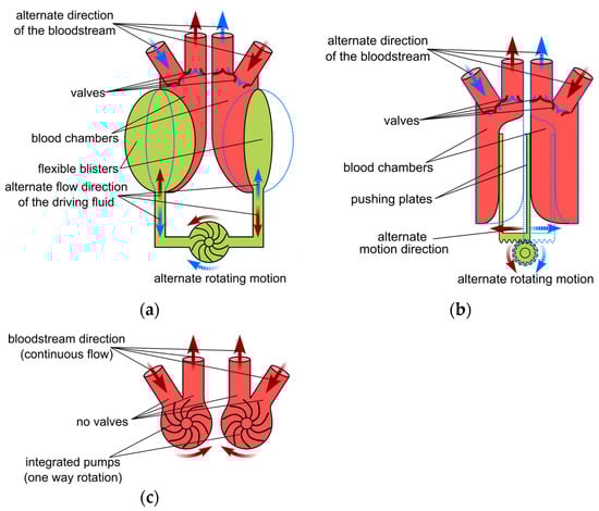
Figure 1.
Main TAH types; (a) fluid driven; (b) electromechanical driven; and (c) continuous flow with integrated pump.
Syncardia TAH-t operates according to a similar principle. Pneumatic drivelines connect the two ventricle chambers to an external pneumatic driver system, allowing coordinated but independent pumping with control over various driving parameters [14]. In [25], a small pneumatic actuator is proposed that can be used as an extracorporeal biventricular assist device. A brushless direct current (BLDC) electric motor drives a ball screw system clockwise or counterclockwise, moving the ball screw system and then generating a two-way airflow through the airline connectors. Two air chambers located at the opposite ends of the moving unit are connected to pusher plates. If the external blood sacs are connected to the airline connectors of the actuator, the two-way airflow is converted to a blood pumping force that pushes and pulls flexible diaphragms in the blood sacs. Although this is based on well-assessed technology, this configuration has several drawbacks, such as its bulky arrangement, noisy operation, need for percutaneous air pressure hoses, poor durability, lack of self-regulatory feedback from the circulatory system, and reduced blood compatibility. Heavily affecting the patient’s quality of life, it can therefore be considered a bridging solution prior to biological heart transplantation.
A similar apparatus based on FD was implemented in the Carmat TAH (Aeson), where the external pneumatic drive is replaced by an internal electrical motor supplied by an abdominal cable connected to external batteries [1,2,18]. The main difference with the AbioCor TAH consists of the presence of four pericardial biomembranes. In every chamber, the flexible membrane acts as a divider and keeps hydraulic fluid and blood on each side. The electric motor-pump group pushes the fluid into and out of the chambers, making the membrane deflect and displace the blood. Four biological valves at the inlet and outlet provide unidirectional pulsatile blood flow. Embedded electronics, microprocessors, and integrated sensors allow auto-regulated responses for the physiological needs of the patient [19]. The large size and mass (1 kg) of the system as well as the need for a portable external power supply system continuously connected to the prosthesis represent its main disadvantages.
Hand in hand with the development of innovative biocompatible materials for membranes and pumping components [26,27], the introduction of more advanced electromagnetic devices in recent TAH projects significantly improved ergonomics, compactness, and control capability. Such features allow for a more accurate heart operation and limit the impact on daily life at the same time. Among the electromagnetic components, transcutaneous energy transmission (TET) systems represent a significant improvement, allowing the implant of long-lasting, small-size rechargeable batteries, paving the way for the prospective implantation of several types of electrical devices together with the main drive.
The first project to implement such technologies was the AbioCor TAH; the internal components consist of [17]:
- The Li-ion battery (discharge time ≈ 20 min);
- The controller that monitors all the implant components and transmits device performance data using radio frequency telemetry;
- The TET coil that receives high-frequency power that is transmitted across the skin from the external TET coil to recharge the internal battery;
- The electromechanical converter that includes a high-efficiency, high-speed centrifugal pump driven by an electric motor; it adjusts the speed according to the different resistances requested to emulate the systolic and diastolic phases;
- A switching valve used to alternate the direction of the hydraulic flow between the left and right pumping chambers.
Even a Japanese project developed an electrohydraulic total artificial heart (EHTAH) system using a TET, a transcutaneous optical telemetry system (TOTS) and an internal battery, which supplies the system for 40 minutes/day [28]. The blood pump actuator is composed of a diaphragm-type blood pump, consisting of a blood chamber and an oil chamber, and a reciprocating electrohydraulic actuator that creates the oil pressure used to drive the diaphragm at alternating intervals. In a revised version, the blood pump and the actuator are connected directly without going through the oil conduit by virtue of the miniaturization of the actuator and the blood pump. Despite the significant volume reduction (500 ml), the pump unit mass was approximately 2.5 kg.
Figure 1b shows the integration of the electromagnetic actuator as a replacement for the fluid pump in an electromechanical (EM) TAH [13]. It exerts a push–pull action on the plates applied to the membrane separating two blood chambers. The linear oscillating motion is accomplished by converting the motor torque using a rotating to linear motion conversion (e.g., by a lead screw transmission) or by a linear electromagnetic actuator directly coupled to the plates. The latter solution would enhance the system reliability and efficiency, even if it requires high force density actuators. As an example, the ReinHeart project [29,30,31,32] proposes a linear oscillating actuator (LOA) that integrates two movers acting separately on each ventricle. A similar approach is adopted in a project under development at the University of Padova [33,34]. Innovative bioengineered tissues are tested to exert the pumping action of artificial ventricular membranes, separating electromagnetic LOA from blood flow at the same time. This solution prevents blood contamination and overcomes mechanical wear and reliability issues related to the rotary to linear motion conversion and likely to the presence of springs and of other auxiliary mechanical devices.
The development of more compact and unconventional magnetic configuration (e.g., axial type) enabled the conceiving of novel configurations, easing the pump integration, and enabling bearingless arrangements. As an example, the continuous-flow (CF) TAH (Figure 1c) is based on two separate blood pumps acting as a biventricular-assisted device [13]. A single or double electric motor directly drives the pumps. It operates through a continuous rotating motion in one direction without requiring valves or additional hydraulic chambers. Devices adopting this principle mock the natural heartbeat by using different speed values managed by the motor controller. The BiVACOR project represents a typical implementation of such an arrangement [35,36,37]. A single axial-flux motor drives the left and right impeller blades of a centrifugal pump, using actively controlled axial magnetic bearings. The axial position of the rotor is adjusted by the signal provided by suitable sensors to control blood flow in the left and right pump vanes.
The importance of innovative technologies, especially based on the introduction of novel electromagnetic devices, is recognizable in Table 1, which reports the main data of some significant TAH projects, approved or in the development stage. All projects except the SinCardia are electrically driven by an implanted motor, allowing for better control capability, reliability, and compactness of the supply system than the pneumatic actuator. Despite the rather scattered distribution and some difficulty in retrieving reliable data, the CF schemes indicatively appear to be the most convenient for the weight and volume, allowing similar performances of the other type at the same time. The only exception is related to the SynCardia TAH, which is, however, penalized by the heavy external equipment. Data on the input power and overall efficiency are more difficult to retrieve and are hardly comparable due to the different supply equipment. Moreover, such values are heavily affected by the load condition. However, percutaneous systems generally exhibit higher efficiency than TET, since the supply of implanted electrical and electronic devices by direct connection implies fewer losses than in contactless transcutaneous power transfer.

Table 1.
Main data from approved or under development TAH projects.
3. TAH Electromechanical Components
The results of the different projects demonstrate that proper TAH operation requires a fully coordinated interaction among the various devices devoted to the supply, control, actuation, and management of all operating phases with a very high level of reliability and efficiency. This section aims to describe the components and their main functions and performances, considering a typical TAH provided with a TET supply system [44] (Figure 2).
In case of percutaneous supply, the external power source supplies the implanted one or the actuation system by cables and connectors (driveline). The components are:
- The heart unit (A), consisting of the integrated actuator and pumps or membranes installed in suitable chambers, possibly provided with valves;
- An external battery pack (B) to supply the external user interface (D), which collects information about the performance of the pumps and of the TET system and tunes the system parameters. A portable lithium-ion battery-type (Li-ion) can power the TAH from 4 to 8 h;
- An implanted auxiliary battery (C), acting as a backup unit in case of the failure of the TET system, usually consisting of a Li-ion battery with a nominal voltage of 13 to 24 V, and with enough capacity to ensure 60 minutes of nominal operation [32,44];

Figure 2.
Typical layout of the devices forming a TET supplied TAH; solid lines: power connections; and dotted lines: data transmission cables.
Figure 2.
Typical layout of the devices forming a TET supplied TAH; solid lines: power connections; and dotted lines: data transmission cables.

- The TET system, composed of the external transmitting coil (F), which in practice is the primary winding of a transcutaneous high-frequency transformer, whose secondary is the implanted receiving coil (G). The electric power collected by G via the inductive coupling enables recharging of the implanted battery (C) and/or supplies the control circuit of the heart unit (F). A bidirectional data exchange is also present, to monitor and adjust the operating condition of the implanted devices;
- The compliance chamber (E), where blood accumulates to avoid overpressures in the ventricles and to facilitate pumping action;
- The microprocessor-based control unit (H), which regulates the operation mode of the heart unit and checks its status. Usually, the closed-loop architecture ensures adequate control robustness, tuning the control strategy according to the parameters provided by the communication cables (from the TET or heart unit sensors).
In the following section, some details of the most important TAH components are given, with particular attention on the up-to-date electromagnetic devices with enhanced performance controllability applied in recent TAH projects.
3.1. Motor Pumps and Bearings
The pumping unit for FD- and CF-TAH must be compact and efficient, manufactured with blood-compliant materials (e.g., polished titanium surfaces) and capable of minimizing common complications, such as hemolysis and thromboembolism [12]. Their design must satisfy different requirements for the operation of the LV and the RV. The pressure volume diagrams of a typical cardiac cycle show that the LV has approximately five times higher pressure during the systolic phase than the RV (140 mmHg vs. mmHg); furthermore, the diastolic phase is much less demanding, as it requires near-zero pressure conditions throughout the stroke volume [45].
The first generation of implantable artificial hearts was pulsatile blood pumps, which can generate pulsatile flow rates and pressures that drive a certain amount of blood with a stroke. A sac-type squeezes and expands a polymer sac pneumatically (compressed air) or hydraulically (silicon oil). Their large size, heavy weight, and large external drive unit that limit patient mobility characterize these pumps. Differently, a pusher plate-type squeezes and expands a polymer sac with hard plates driven by electric motor/gear mechanism or by an electromagnet [46,47].
Continuous-flow pumps are mainly considered as the second generation of MCS devices, providing better efficiency and reliability. Centrifugal pumps (CFPs) or axial flow pumps (AFPs) are more commonly adopted (Figure 3) [48]. Although originally conceived for LVADs, they can also be implanted to drive TAHs. The hemocompatibility with the contact materials of the impeller/housing (biocompatible titanium and polyurethane) is generally very good without worsening the hydraulic performances. Biocompatible compounds encapsulate the electric motor to avoid any contact with possible toxic materials.
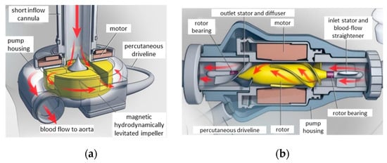
Figure 3.
Pump types for LVAD and TAH applications; (a) centrifugal flow with a magnetic bearing for impeller suspension; and (b) axial flow with a conventional bearing. Republished with permission of Massachusetts Medical Society.
Typically, they operate to convey a constant flow, varying the motor speed [49]. CFPs apply centrifugal force to suck the blood from the inlet and pump it tangentially to the pump housing through the outlet. In contrast, AFPs drive blood flow, both rotationally and axially, conveying it in line with the shaft axis. The CFPs are recognized to benefit from several features with respect to AFPs, some of which are worth mentioning:
- Linear dependence of the output flow on the motor current across the full range of the operating pump flow, enabling the pump operation to be monitored and controlled straightforwardly by means of the current value;
- The flat head curve (greater change in the flow rate for any given pressure gradient across the inlet and outlet of the pump) that enables the mimicking of the pulsatile flow variation between diastole and systole. Such a feature also provides a more accurate flow estimation from the pump speed and power;
- Easier integration with axial flux PM motors, resulting in a more compact rotor design, due to the disk-shaped configuration and the direct pump impeller-PM rotor coupling [36,50];
- Easier implementation of magnetic bearing suspension, allowing a larger gap between the rotor and the stator and improving reliability (absence of lubrication and sealing) and efficiency (no friction losses).
Figure 4 shows the different magnetic bearing configurations for the CFPs. In Figure 4a, the hydrodynamic thrust generated by the blood pressure on the tapered surface of the impeller combines with the alignment force acting on the fixed and rotating PMs, compensating the dependence of the magnetic force on the rotor position. The electromagnetic bearings in Figure 4b couple passive and active control actions to stabilize the rotating parts along all degrees of freedom (DOFs).
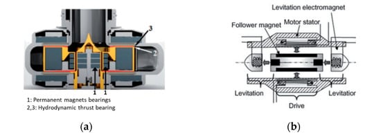
Figure 4.
Magnetic bearings for blood pumps; (a) PM assisted by hydrodynamic thrust bearing; (b) electromagnetic bearings; (c) bearingless axial flux motor for CFPs; and (d) bearingless BLDC motor for CFPs. Republished with permission of IEEE.
However, the regulation of the bearing coil current by active control requires axial and/or radial gap sensors. Figure 4c shows how coupling the pump to a bearingless motor in a CF-TAH leads to a more compact design: there are eight PMs on each rotor side, facing two distinct concentrated stator windings, one of which is for motoring and axial control and the other for tilt control, thus providing full active control for all DOFs [51]. This configuration ensures a relatively large clearance between the rotating and static parts and the accurate rotor-impeller position control. The latter feature enables the flow modulation through the two ventricles to meet the different requirements of the LV and RV [36].
Unlike CFPs, the flow in AFPs cannot be accurately evaluated without a flow sensor; moreover, at a lower flow rate, the risk of tissue damage of the tissues around the inlet channel increases as a result of a higher inlet suction. Due to the high axial force component, the AFP impeller requires an adequate support bearing, whose reliability and efficiency are critical issues. Furthermore, it is difficult to reproduce natural pulsation unless a suitable rotation speed control operates the thrust modulation.
Alternatively, an oscillating pushing plate driven by a suitable-shaped bearing mounted on the motor shaft can replace the impeller [52]. Another mechanical arrangement involves the adoption of an undulation pump composed of a pump housing with a partition between the inlet and outlet ports, a disk with a slit located in the partition of the housing, an undulation shaft at the center of the pump, and a pair of seal membranes between the disk and the housing to seal the shaft from the pump room [53]. The mechanism of the undulation shaft prevents the rotation of the disk and converts the rotation of the shaft to the wave motion of the disk. A close line between the disk and the housing enables blood squeezing from the inlet to the outlet of the pump. A TAH requires two of such units that need the implementation of a rather sophisticated hierarchical control protocol [54].
More conveniently, electromagnetic bearings can compensate for axial and radial force components, as in the implementation described in Figure 4d [55]. The impeller is mounted on the inner surface of the hollow rotor, and the suspension of the rotor is based on two passive radial magnetic bearings at the ends of the impeller and an electromagnetic actuator to control the axial position. The main issue is the presence of uncompensated oscillations in the radial directions related to the actuator axial control.
Based on the implementation of magnetic bearings, a novel design concept has been proposed for the Dragon Heart at Drexel University [56]. The hybrid design integrates two blood pumps for pediatric patients, in which an axial pump impeller supports the right side of the heart and the pulmonary circulation, and a centrifugal pump impeller supports the left side of the heart and the systemic circulation (Figure 5). By such an arrangement, they share a common rotational axis with distinct fluid domains. Magnetic bearings lift the rotating impeller inside the pump housing and facilitate much wider clearances between the rotating and stationary domains, thus reducing fluid shear stress levels.
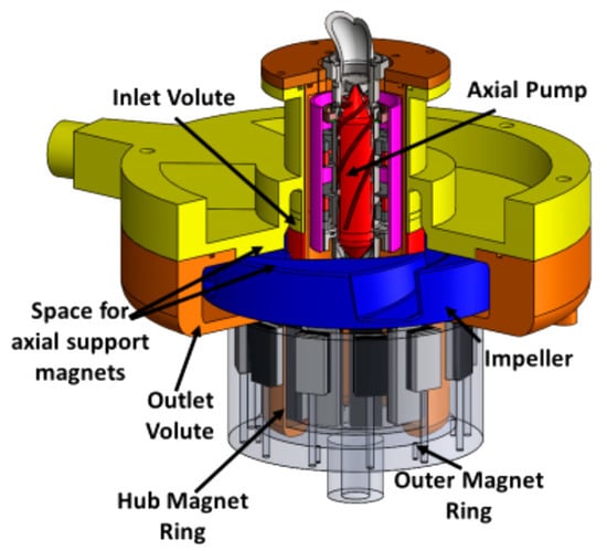
Figure 5.
Design concept of the Dragon Heart pediatric TAH integrating an axial and centrifugal pump with magnetically levitated impellers [56]. Republished with permission of John Wiley and Sons.
The design is shaftless and guided by two magnetically coupled PM rings with radial magnetization: one is placed on the extended hub physically coupled to the impeller (hub PM ring), the other one is driven by an external BLDC motor (outer PM ring). The passive radial suspension denoted some limitations in combination with the hydrodynamic bearing, as high shear stresses occurred in areas with narrow fluid gaps, resulting in wear problems on the interior of the inner magnet ring. The implementation of a fully active magnetic suspension was therefore advised for future development.
An alternative to CFPs and AFPs is represented by the helical flow pump (HFP) proposed in [57], which reproduces the amplitude and frequency variations of physiological pulsation by modulating the rotation speed without requiring complex bearings due to the hydrodynamic impeller suspension. However, a minimum rotational speed is required to maintain an adequate clearance between the rotor and stator; moreover, the suitably trapezoid-shaped voltage waveform prevents instability arising due to eccentric force.
3.2. Electrical Drive
According to the different projects, the electric drive implemented in a TAH can be broadly divided into speed controller-based and position (or force) controller-based arrangements. The speed control is applied to reproduce the operation for both continuous and pulsatile flow. Three-phase or multi-phase motors are generally supplied by a voltage source inverter, often operated by space vector modulation. The PID speed controller elaborates the speed signal generated by Hall-effect sensors or sensorless, estimated in more sophisticated microcontroller-based strategies (e.g., field orientation) [36]. In the latter case, a more precise and reliable control can be achieved, for instance, by providing an active braking control to decelerate the impeller motor and then allowing energy recovery during the braking operation.
The elaboration of appropriate speed profiles enables the achievement of the pulsatile effect with a satisfactory hemodynamic response. Generally, they consist of roughly square waveforms of the desired heartbeat frequency that oscillate between two limit values. As an example, in [36] a mean aortic pressure of 102 mmHg and a maximum pressure slope of 240 mmHg/s are achieved at 30 bpm by varying the speed between 2300 and 2900 rpm. However, control parameters must be tight to the proper values, since in vivo experiments show that even slight alterations (i.e., short-term speed overshoots or control delays) can significantly alter pump outflow.
A specific controller must be expressly designed to drive the active magnetic suspension of the rotor/impeller shaft, generally operating along the axial and possibly also the radial directions, even if a passive bearing (e.g., hydrodynamic journal bearing) can be effective in controlling the radial position. In an application based on an axial flux motor, three eddy current sensors detect the axial position and send their signals to the PID controllers [35]. Accurate coordination between the controllers of the axial position and of the motor speed enables the regulation of the LV and RV outflow. The bearing control must be tuned to cope with both hydraulic forces, depending on the motor speed and the rotor position, and the inherent magnetic attractive force between the PMs and the iron core of the motor. As an example, the power to supply the windings of the hybrid PM-electromagnet bearing for the maximum axial displacement of 0.15 mm at a speed of 2200 rpm is limited to 10 W. The overall consumption under the same conditions is below 15 W [35].
In the LOA configuration proposed in [32], each motor coil is generally powered by a separate DC/DC full-bridge converter, with a PWM current control and a relatively low supply voltage (between 12 V and 20 V), adequate for the low coil inductance and back-e.m.f.. The drive control enforces the predefined reference sinusoidal motion using a sensor feedback signal giving the position of the pusher plates, adjusting the supply current value to the required thrust, depending, in turn, on the blood outlet back pressure and on the pump speed. A proper motor design and an effective control strategy (e.g., field orientation) should aim to maximize the thrust/current ratio, i.e., to minimize the losses/output energy ratio, in order to avoid overheating and to extend the battery range. The electromagnetic cogging force could possibly contribute to the thrust by taking advantage of a suitable iron core design.
3.3. Energy Transmission
The TET unit enables the elimination of the percutaneous cable connection to supply the implanted equipment. Figure 6a outlines a basic layout of the external and internal circuit components involved in both power and information transmission [58,59]. The external AC source consists of a battery and a high-frequency full-bridge MOSFET inverter. Biologic tissues impose a large gap between the transmitting and receiving coils (typically 5–15 mm), which require high-frequency operation (100 kHz) and ferromagnetic coil casing, also for magnetic field confinement [60]. Litz wires and ferrite magnetic pot cores are therefore needed to limit the electromagnetic losses.
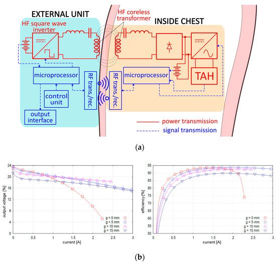
Figure 6.
Layout and performances of a TET system; (a) scheme of the power and information circuits [59]; and (b) rectifier output voltage and efficiency for different air-gap values.
Using MOSFETs instead of diodes in the synchronous rectifying stage enables a remarkable reduction of conduction losses, which can be further reduced by SiC-based devices, thereby limiting the possible risks of tissue damage due to overheating. Experimental analyses of the generated waveforms showed that this converter type is less affected by deviation from the rated axial displacement (−20% variation of the output power at 20% of the axial displacement) [61].
Figure 6b reports the typical output current/voltage characteristics for different air-gap values [60]. The voltage is stable (18 V–21 V for normal operation) for in the 5–10 mm range; however, for 0 mm, it suddenly drops as the load increases due to the higher internal impedance. The transfer system delivers up to about 50 W, sufficient to supply the TAH during its normal operation and recharge the implanted battery at the same time. The maximum efficiency is over 90% under typical load conditions, due to properly sized series capacitors on both transformer sides compensating for leakage inductances. An integrated system that detects the temperature of the secondary coil elaborates the feedback signal of the output power, allowing one to adjust the input power in the primary coil and improving the system [59].
4. Linear Electromagnetic Actuators
Linear oscillatory actuators (LOAs) are the most promising candidates for reproducing the natural heart operation, exerting their pumping effect by the electromagnetic interaction between the m.m.f.s generated by the stator and mover components (windings or PMs). They are particularly profitable in the electromechanically driven TAH configurations shown in Figure 1b, due to the smallest amount of force transmission components and the feasibility of their complete physical separation from blood flow.
4.1. LOA Ratings
The applications of LOAs for TAH have been presented in several studies, analyzing different electromagnetic configurations and sizes, with their respective different supply characteristics and electromagnetic performances. Data collected from the literature are specifically related to single-mover TAH or LVAD applications, with the following broad ratings [62]:
- Radius/active length: 32–40 mm/20–40 mm;
- Stroke length: 8–18 mm;
- Volume: 90–180 mm3;
- Peak force/force density (): 40–140 N/0.18–0.88 N/cm3;
- Average LV/RV force (systolic phase): 50–70 N/15–30 N;
- Maximum values for mass/losses: 1 kg/20 W.
The different pumping force requirements evidenced by the last specification data imply distinct LOAs or additional hydraulic devices to drive both ventricles simultaneously for a full TAH operation.
4.2. PM-LOAs
Even if various potentially applicable LOA typologies could easily be borrowed from numerous short-stroke industry applications (compressors, pumps, vibrators, etc.), PM synchronous motors, regardless of the variable reluctance (VR), are the best suited to meet the requirements of high efficiency and force density for TAHs [63,64]. It is worth pointing out that the installation in a chamber separated from blood sacs avoids any contact, and then no biocompatibility issues arise with the actuator materials (e.g., PM material). Demagnetization issues can be avoided by adopting suitable NdFeB grades and PM thickness at the design stage. PM-free LOA are also considered for an LVAD actuator [65]. Their simple and inexpensive manufacturing as well as their straightforward control strategy represent significant features for possible TAH application. However, the production of high reluctance force requires a very high current density and a very small air-gap length, which is difficult to implement in miniaturized devices. As a result, tends to be too low for a TAH application. For example, the rated thrust density of the linear switched reluctance actuator analyzed in [65] is 0.06 N/cm3 at 10 A/mm2 and with 0.2 mm air-gap length.
Tubular PM configurations are preferred because they best fit the available volume between the ventricle chambers. The most effective quadrature condition between coil m.m.f. and PM magnetic field can hardly be achieved with ordinary single-phase supply, taking into consideration the short stroke and other electromagnetic effects (e.g., longitudinal end effects, magnetic saturation, and cogging). A proper design, possibly involving the magnetic core shape, the PM magnetization pattern, and a suitable supply current switching strategy can mitigate force ripple, providing an adequate thrust average value at the same time.
PM-type LOAs can be divided into coreless moving coils (MC-LOA) and moving PMs (MM-LOA), provided or not with back iron, according to the PM magnetization pattern. In MC-LOAs, the supplied coils slide along stationary PMs, mounted on a back-iron core, or enclosed between two core flux concentrators (Figure 7a). The confinement of PM flux generally requires rather bulky cores; moreover, the moving coils should be divided into sections supplied separately with a proper sequential current control to equalize the thrust profile and limit winding losses, since the Lorenz force is proportional to the ampere-turns of the motor coil portion passed through by the PM magnetic flux [32].
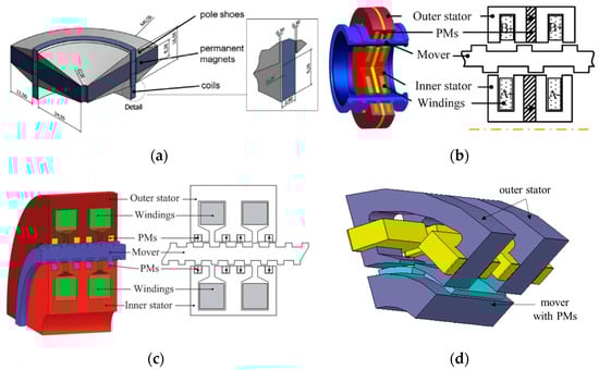
Figure 7.
Examples of PM-LOA configurations; (a) PM stator with moving coils [30]; (b) double U-shaped stators with PM, windings, and VR mover [66]; (c) cross section of a double E-shaped stator tubular Vernier PM-LOA [67]; and (d) 3D schematic portion of the transverse-flux MM-LOA [69]. Republished with permission of Elsevier and IEEE.
In MM-LOAs, the PM mover slides alongside the stator core with a C- or E-shaped cross section, enclosing a single- or a double-coil winding. With respect to MC-LOA, the stator coil supply benefits from a faster dynamic response and lower ohmic losses. Moreover, slotted configurations can take advantage of the cogging force in the forward stroke, resulting in an effective reduction of ohmic losses, although possibly impairing the backward stroke motion. Electromagnetic interference with other devices because of the PM flux leakage at the stroke ends and the eddy current losses in the ferromagnetic cores are other possible issues.
Alternatively, both the PMs and the coils could be placed on the stator and could interact with a passive VR mover. Such a geometry complicates small-sized stator manufacturing, and it requires very low air-gap length (0.3–0.5 mm) to enhance the modulation effect of the coil m.m.f.. However, it enables adequate thrust density and PM flux confinement. For example, in [66] a hollow-type mover is proposed that slides between two U-shaped stator rings (Figure 7b). Cogging force minimization calls for a suitable mover slotting design based on a half-period shift between the inner and outer parts. The supply of the stator coil pair by 90° phase displacement yields 0.57 N/cm3.
In the Vernier-type configuration, the insertion of PMs in the stator teeth slots enhances the thrust density at the expense of increased supply frequency, taking advantage of the multiplication effect of the reluctance force. In [67], the peak force using the double E-shaped stator of Figure 7c is 70 N; however, it has a significant ripple (30 N). The single E-shaped stator proposed in [68] enables a robust structure and a high force density by combining two different PM magnetization directions of PMs and ferromagnetic poles. The quasi-Halbach magnetization significantly enhances the thrust performance ( 0.75 N/cm3) with respect to a pure radial one, halving at the same time the peak value of the cogging force.
A transverse flux configuration (Figure 7d), originally proposed for a compressor application, consists of an inner stator yoke, a concentrated armature winding enclosed between the ferromagnetic poles of two outer stators, and a six-PM mover sliding between the inner and outer stators [69]. The prevailing radial orientation of the flux lines enables the adoption of axially laminated stator yokes to reduce the eddy current losses. A single-phase sinusoidal current supply combined with the connection of the mover ends to a flexible spring gives rise to a reciprocating motion. A 100 N thrust is achieved for a 10 mm stroke length. However, the design must consider the radial forces that act on the PMs for the reliability of the system.
Despite a possible lower thrust density and an uneven thrust profile, MM-LOA are deemed to be the most convenient for the TAH application because of the easier manufacturing process and their higher suitability to comply with strict size constraints. Therefore, the main proposed configurations and related performances are discussed in the following subsections.
4.3. Single-Mover MM-LOA
According to the stator configuration, the following arrangements have been proposed:
- E-shaped stator cross section with a pair of coils supplied by opposite currents [62], [70,71,72,73,74];
- Single or dual C-shaped stator cross section, the latter with coils supplied by opposite currents [71,75,76];
- Stator with multiple coils to allow multiphase or fault-tolerant supply [77,78,79].
The latter configurations can benefit from the smooth force profile and emergency operation in case of a partial winding fault; however, the mitigation of the radial and cogging forces possibly requires slotless stator and quasi-Halbach PM magnetization, resulting in winding oversizing and higher losses due to the high equivalent air-gap.
The most common stator configurations are those with C or E shapes, combined with different types of movers, differing in the magnetization pattern, pole number, and yoke assembly. Figure 8 shows two typical configurations with the corresponding force profiles determined at constant total ampere-turns, with the outer radius, air-gap, stroke length, and ohmic losses being the same. Regarding the E-shaped stator with the interior PM (IPM) mover, the C-shaped stator with surface PM mover (Figure 8a) provides a higher peak force but suffers from higher thrust unevenness. Furthermore, the PM and mover masses are 20% and 80% higher, respectively. The optimized IPM mover provides 0.47 N/cm3.
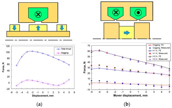
Figure 8.
Examples of MM-LOA and related force performances; (a) C-shaped stator with surface PM mover [71]; and (b) E-shaped stator with IPM mover [71,73] (outer radius: 32 mm, air-gap: 1 mm, and stroke: 5 mm). Republished with permission of IEEE.
Considering additional mover PM configurations, the E-shaped configuration seems more favorable, as it limits the leakage flux along the entire stroke and yields a force density higher than that of the C-shaped one. The adoption of a quasi-Halbach type provides an even more uniform thrust profile. The application of ferromagnetic rings to the mover ends increases the average thrust, due to the higher magnetic flux [74]. On the other hand, such a design increases the mover mass and the coil inductance.
4.4. Dual-Mover MM-LOA
In general, the literature suggests integrating LOA into VAD applications, replacing the function of a single ventricle. To emulate the complete functionality of the biological heart function, the TAH must drive two distinct components. The arrangement in Figure 9a shows a dual-mover LOA enclosed in a sealed cavity between two flexible pockets, provided with non-return valves, mimicking the ventricular operation. The LOA stator interaction with two distinct movers impresses on the latter ones, reciprocating opposite synchronous motion with alternative compression and dilation of the pockets to infuse the blood flow.
Figure 9.
Double-mover LOA; (a) working principle showing the two movers pushing the ventricular chambers; (b) LOA electromagnetic configuration; , : PM movers acting on the LV and RV; , : thrust acting on and ; : mover position with respect to the backward bound; and sizes are in mm. Republished with permission of IEEE.
Again, the tubular configuration is particularly profitable. The main features of the E-shaped stator with two PM movers ( and ) analyzed in [62] are:
- Identical radially magnetized NdFeB-48 PMs in a repulsive configuration;
- Two distinct coils, enclosed in the outer high permeability stator core (CoFe alloy) and supplied by reverse currents to produce opposite thrusts in the nearby movers;
- The cross sections of the LV and RV coil cross sections are proportional to the related ampere-turn and , respectively, in turn proportioned with the corresponding rated thrust peak values 70 N/25 N;
- A fixed hollow core in the inner part to provide a return path for both the PM and winding fluxes.
High-performance magnetic materials are mandatory to satisfy the very binding limits on the overall volume (153 cm3) and the active part mass (<1 kg). The moving mass is very low as well since movers have no back iron.
Figure 10 reports the thrust as a function of the mover position for different values of and , with a maintained constant over all the stroke length (15 mm), a maximum current density of 6 A/mm2, and total ohmic losses of 13 W. Eddy current losses can be assumed to be negligible because of the low-frequency operation (1.3 Hz). The force profiles evidence the following aspects:
- The cogging force ( 0) benefits the forward stroke for both movers;
- Inverting the LV coil supply current near the end of the stroke (see point ) increases the thrust, which otherwise would even become negative, producing a braking effect;
- Due to the mutual linkage between the coils, the simultaneous current inversion in both coils slightly worsens the RV thrust;
- A residual cogging force opposes the backward motion in both movers (points and ), regardless of the current value.
Parametric analysis that involves the sizes of the main PM and the stator core, as well as the more convenient position switching the current in both coils, leads to the optimized force profile shown in Figure 11.
Figure 11.
Thrust as a function of the mover position with current switching at 12.2 mm; (a) LV mover; and (b) RV mover.

Figure 10.
Thrust profiles as functions of the axial mover position for different ampere-turns; (a) LV mover; and (b) RV mover.
Figure 10.
Thrust profiles as functions of the axial mover position for different ampere-turns; (a) LV mover; and (b) RV mover.

With constant power losses being predefined, various performance indices are considered, which mainly takes into account the TAH forward stroke operation. The profiles calculated by 2D finite element analyses are sufficiently smooth for most of the forward stroke, satisfying the peak force requirements (71.2 N for the LV, −36.8 N for the RV) and with satisfactory mean values (58.2 N for the LV, −25.4 N for the RV). The supply voltage to compensate both the resistance voltage drop and the induced counter e.m.f. is lower than 20 V, therefore being consistent with the portable battery pack.
The cogging force, leading to a deadlock near the outward stroke end, represents a major concern for the backward stroke, especially for the RV mover, even if during such a phase a limited blood back-pressure aids the return motion. Therefore, the magnetic configuration should be refined to match the electromagnetic force with the counteraction of the circulatory system, as well as with the effect of the blister deflection.
5. Unconventional Electromagnetic Actuators
Other alternative configurations, aimed at overcoming issues related to the size and operation, can be grouped into two PM actuator categories. The former is based on the contactless electromagnetic interaction between the external static or rotating primary and the secondary part implanted in the chest ribs, neither requiring additional implanted batteries nor percutaneous cable connection, however, requiring very tight magnetic coupling. The latter includes actuators combining both linear and rotary (2 DOFs) motion to produce both the pumping function and valve actuation, respectively, to manage blood flow during the TAH operating cycle. The following sections describe some examples of the two types of actuators.
5.1. Contactless Power Transfer (CPT)
Two approaches are proposed for this kind of actuators. The first one relies on external moving PMs, driven by a conventional rotary electric motor, magnetically interacting with inner PMs to produce a pumping function without using any winding. The absence of copper losses significantly limits thermal issues related to both the power transfer and the actuator operation. Other benefits are the very compact assembly, particularly profitable, for instance, for pediatric application, the ease of setting and tuning of the main drive control, and the low risk of infection transmission.
In Figure 12a, a rotating motor supplied by a separate source (i.e., external battery pack) drives a disk-type version of the actuator with an external 2-pole ring-shaped PM rotor [80].
Figure 12.
Configurations for the contactless mechanical power transfer; (a) external rotating PM disk coupled with an implanted reciprocating PM disk; and (b) external 2-phase coils supplied by 90° shifted sinusoidal currents interacting with a 2-pole PM rotor.
During rotation, the axially magnetized PMs alternately repel and attract the inner 2-pole PM ring, constrained to a linear reciprocating motion by mechanical coupling to a spline shaft. A diaphragm, which separates the blood flow from the oscillation chamber, prevents any contamination and hemolysis problems. The reinforcement of the air-gap flux density by an iron yoke and a proper selection of the diameter of the disk hole yields peak values of the attractive and repulsive force at least of 55 N and 15 N, respectively, with a minimum air-gap length (skin thickness included) and a disk outer diameter of 10 mm and 63 mm, respectively. Instead of rotating, in normal operations the prime motor swings through a 180° angle. The maximum output pump power is 0.65 W at an average speed of 92 rpm with a blood flow of 8 l/min. The total pumping efficiency is 32%, appreciably higher than other conventionally motor-driven TAHs.
The same principle applies by replacing the axial flux configuration with a radial flux one, where the rotating magnetic field generated by an external stator primary poly-phase winding interacts with an implanted cylindrical PM rotor. Figure 12b describes a two-phase winding arrangement in [81]. The effective interaction area is limited by the chest curvature; moreover, flux leakages are relevant because of the absence of back iron. However, no shaft or mechanical bearings are required, and the pump impeller can be integrated with the rotor without any mechanical coupling. The pump sized for pediatric VAD was successfully tested in animals that produced an average flow rate of 1.5 l/min at 50 Hz (3000 rpm) with a 2–3 cm distance between the pump and the driving coil. Pump efficiency is approximately 20 to 40% at the average flow rate (1.7 to 2.0 l/min), with a speed ranging from 3000 rpm (50 Hz) to 6000 rpm (100 Hz).
An alternative to the configuration of Figure 12a could consist of a linear-to-linear motion transmission using external and implanted rectified PM arrays [82]. Such a configuration corresponds to a magnetic coupler, where the inner PM array is driven by the motion of the outer one. Such an arrangement is claimed to be immune to the shortcomings due to fatigue in the flexible blood pockets of most state-of-the-art bionic pneumatic or electric blood pumps. The outer active PM array is driven by a linear motor or by a rotary motor coupled to a rotary-linear motion converter. The piston enclosed in the pump casing holds the passive magnet; the casing is provided with openings on both ends connected to the aorta and the vein, respectively. A one-way valve allows blood flow from the chamber connected to the aorta to the vein, reproducing diastole in the natural heart. Simulations with NdFeB hexahedral 2-pole PMs (sizes: 30 mm × 20 mm) distanced by 60 mm evidence the feasibility of the configuration, providing 1.2 W at 70 bpm.
The effectiveness of the above solutions clearly relies on a precise alignment between the primary and the secondary, reducing the air-gap as much as possible between the two parts. Therefore, such a condition, which is quite critical during physical activities, requires a stable fixture of the external part. The linear-to-linear motion transmission also suffers from the low efficiency of the linear prime mover and of the rotating to linear motion converters.
5.2. Linear Rotary Actuator (LiRA)
Linear rotary motion can be obtained by two different approaches: magnetic conversion (MC-LiRA) from a rotating motion impressed by a conventional electric motor into a linear one by using PMs and possibly ferromagnetic parts (passive configurations), and straightforward generation of a roto-translating field in a single device (conventional LiRA) using supplied windings (active configurations).
MC-LiRAs have been conceived for different applications that require a short stroke and a high thrust [83]. The Magscrew TAH project has already implemented such an actuator [84]. The operating principle is based on the concept of a magnetic screw–nut (Figure 13a). Surface PMs with helicoidal distribution mounted on the back of the screw and on the nut move in synchronism, driven by the corresponding pole interaction. Motion control is in charge of a prime rotating motor, which must produce a clockwise and counterclockwise torque to develop a reciprocating thrust force . The relation to be fulfilled between the torque and force is (: pole pitch). With Halbach magnetization and properly sized PMs, with an outer nut diameter of 17 mm and mover length of 12 mm, a thrust higher than 100 N is achieved. An actuator based on this concept, implemented in in vivo experiments, achieved a blood flow greater than 8 l/min and a maximum pressure of 100 mm Hg, with a device beat rate ranging from 157 to 249 bpm [85].
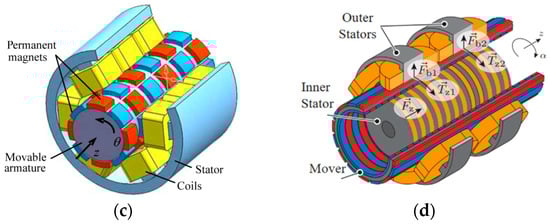
Figure 13.
Linear rotary actuators; (a) magnetic screw–nut configuration; (b) field modulated magnetic screw; (c) linear and rotary PM actuator with stator coils; and (d) self-bearing linear actuator with double stator winding. Republished with permission of AIP Publishing and IEEE.
A field-modulated magnetic screw, proposed in [86], is based on the concept of a magnetic screw and a linear magnetic gear. An intermediate translated set of helically ferromagnetic pole pieces modulate the magnetic field produced by outer static helically shaped PM arrays (Figure 13b). Therefore, its interaction with the inner side rotating PMs enables the conversion of the torque applied to the rotor PM screw into thrust by acting on the intermediate ferromagnetic translator. The increase of the thrust to torque ratio by the gearing effect relies on satisfying the relation , with number of ferromagnetic pole pieces, and number of pole-pairs on the rotor, and stationary screws, respectively. Such actuators can achieve a force density of up to 20 N/cm3, consistent with TAH requirements, even if their placement must consider the presence of the prime motor and the troublesome manufacturing of very small helicoidal parts.
Conventional LiRAs with supplied stator winding are attractive in modern machine tools and robotics because of their ability to provide motion with two degrees of freedom. However, their inherent tubular configuration makes them suitable for TAH application; moreover, because of the possibility of the independent management of rotation and translation, their control is more straightforward and flexible than in MC-LiRAs. In this field, VR PM-free configurations are also proposed. The most significant ones rely on rotary-linear switched reluctance motors (RL-SRMs), as they benefit from simple but robust construction, low manufacturing and maintenance costs, high reliability and fault tolerance, and easy control [87]. They can present a multi-stack assembly of classical SRMs with suitably displaced rotors, where an adequate supplying sequence of the stator coils can provide the rotation or linear movement.
Alternatively, they can be provided with two separate sections: a rotating section for clockwise–counterclockwise motions in the middle and a linear section for the forward–backward movements at the actuator sides. Despite its attractiveness for some applications (pick and place machines, robotics, and automotive), RL-SRMs suffer from the main limitations of its LOA counterpart in terms of thrust density ( 0.02 N/cm3 in [88]), making its application for a TAH unattractive.
Figure 13c shows a basic PM LiRA. There are 48 alternately polarized PMs, 6 in the -direction and 8 in the -direction, and a stator with 18 concentrated coils, 3 in the -direction and 6 in the -direction, broadly representing a 9-phase system [89]. Possibly, a salient stator inside the PM mover can exploit the Vernier effect to improve the force/mass ratio and the evenness of the torque/force profile [90].
Integrated magnetic bearings are also useful in eliminating mechanical wear problems [91]. It uses a double-stator arrangement placed concentrically inside and outside a cylindrically shaped mover (Figure 13d). The outer stator coils provide the rotating motion (torque and ) and the bearing function (forces and ) by an appropriate air-gap control, while the inner stator coils control the linear motion (thrust ).
6. Overall Comparison
To summarize the detailed overview provided in the previous sections, Table 2 reports a qualitative comparison of the designed and tested electromagnetic actuators, considering five significant properties (maturity level, compactness, manufacturing, control simplicity, and efficiency). The limited consistency of both the geometric and operational data as well as the unavailability of some information did not allow for a quantitative performance comparison. The overall evaluation points out the following considerations:
- The brushless motor (DC or AC) presents the highest maturity level because of its widespread ability in many low-rated applications, therefore ensuring high reliability and flexible control; however, in FD- and EM-TAH, the overall efficiency can suffer from the presence of gear or hydraulic converters, and in CF-TAH, the control can be more complicated in presence of magnetic bearings;
- The VR-LOA is the least suitable, as the manufacturing and control simplicity is by far offset by the limited thrust density and efficiency, the latter related to the required high current density;
- Among THE PM-LOAs, the MM one seems slightly better in terms of manufacturing simplicity, because no moving coils as well as complicated stator assembly are present;
- The CPT systems provide a promising performance and likely the most compact configuration as only the moving part is implanted; however, control issues can arise in the presence of misalignments or increased axial distancing between the external and the implanted parts;
Table 2.
Overall comparison of the main actuators for TAH applications.
Table 2.
Overall comparison of the main actuators for TAH applications.
| TAH Type | Actuator | Maturity | Compactness | Manufacturing Simplicity | Control Simplicity | Overall Efficiency |
|---|---|---|---|---|---|---|
| FD | Brushless motor | High | Low | Medium | High | Medium |
| EM | Brushless motor | High | Low | Medium | High | Medium |
| CF | Brushless motor | Medium | Medium | Medium | Low | High |
| EM | VR-LOA | Low | Low | High | High | Low |
| EM | MC-LOA | Medium | High | Medium | Medium | High |
| EM | MM-LOA | Medium | High | High | High | High |
| EM | PM VR-LOA | Low | Low | Low | Medium | Medium |
| EM | CPT | Low | High | Medium | Low | High |
| EM | MC-LiRA | Medium | High | Low | Medium | High |
| EM | Conventional LiRA | Low | Medium | Low | Low | High |
- LiRAs have no distinguished merits due to their still limited development and manufacturing complexity; however, the possibility to combine mover rotation and translation could lead to the simplest operational management for a TAH (pumping and blood flow control).
7. Conclusions
In the paper, different electromagnetic technologies considered for application in a ventricle-assisted device or a totally artificial heart (TAH) are presented. The review examined the innovative solutions utilized in the most promising projects focused on the development of the total system, as well as those proposed and checked in the literature as single components. Among all the devices, the transcutaneous energy transmission (TET) system and the electromagnetic actuator are distinguished in terms of performance and durability. In view of the possible application of new high-performance materials (e.g., high-energy PMs, low core loss, high permeable magnetic materials, and Litz wire windings), very high achievable efficiency and power density are achievable, enabling compact configurations with limited losses and positively affecting both battery life and heat generation.
As for the TET, despite the inherent significant air-gap due to the biological tissue thickness, the high-frequency operation enables efficiency up to 90%. For the actuator, two solutions seem very convenient and effective. The first one, adopted in the BiVACOR project, relies on an axial flux PM motor that interacts with an axial magnetic bearing, integrating both the pumping and the pulsatile effects in a rotating motor. The other one is based on a linear oscillating actuator (LOA), acting on both artificial ventricles realized in biocompatible materials. Among the various families of PM-LOAs that can effectively mimic the heart operation, the seemingly most advanced one is applied in the ReinHeart project, but other configurations exhibit favorable features (dual-mover, linear-rotating motion, and bearingless arrangement) and are potential candidates for a future commercial TAH.
Author Contributions
Formal analysis, M.A.; investigation, E.F. and A.T.; data curation, E.F.; writing—original draft preparation, E.F.; writing—review and editing, M.A. and A.T.; supervision, M.A. and A.T.; funding acquisition, A.T. All authors have read and agreed to the published version of the manuscript.
Funding
This research was funded by the Department of Industrial Engineering–University of Padova, under the project entitled “Reliable and minimally invasive electrodynamic actuator for longer lasting artificial heart” ID TORT_BIRD2121_01.
Conflicts of Interest
The authors declare no conflict of interest.
References
- Yang, M.; Zhang, Y. Introduction to Artificial Hearts. In Artificial Hearts, 2nd ed.; Yang, M., Ed.; Springer Nature: Singapore, 2020; pp. 1–19. [Google Scholar]
- Watt, T.M.F.; Pagani, F.D. Artificial mechanical hearts and ventricular assist devices. In Emerging Technologies for Heart Diseases, 2nd ed.; Nussinovitch, U., Ed.; Academic Press: Cambridge, MA, USA, 2020; Volume 1, pp. 25–40. [Google Scholar]
- Phillips, K.G.; Ranganath, N.K.; Moazami, N. Status and Availability of a Total Artificial Heart. In Mechanical Support for Heart Failure; Karimov, J.H., Fukamachi, K., Starling, R.C., Eds.; Springer Nature: Cham, Switzerland, 2020; pp. 191–220. [Google Scholar]
- Jefferson, H.L.; Kent, W.D.T.; MacQueen, K.T.; Miller, R.J.H.; Holloway, D.D.; Hassanabad, A.F. Left ventricular assist devices: A comprehensive review of major clinical trials, devices, and future directions. J. Card. Surg. 2021, 36, 1480–1491. [Google Scholar] [CrossRef] [PubMed]
- Andrade, A.; Nicolosi, D.; Lucchi, J.; Biscegli, J.; Arruda, A.C.; Ohashi, Y.; Mueller, J.; Tayama, E.; Glueck, J.; Nosé, Y. Auxiliary total artificial heart: A compact electromechanical artificial heart working simultaneously with the natural heart. Artif. Organs 1999, 23, 876–880. [Google Scholar] [CrossRef] [PubMed]
- Andrade, A.; Fonseca, J.; Legendre, D.; Nicolosi, D.; Biscegli, J.; Pinotti, M.; Ohashi, Y.; Nosé, Y. Improvement on the Auxiliary Total Artificial Heart (ATAH) Left Chamber Design. Artif. Organs 2003, 27, 452–456. [Google Scholar] [CrossRef] [PubMed]
- Cohn, W.E.; Timms, D.L.; Frazier, O.H. Total artificial hearts: Past, present, and future. Nat. Rev. Cardiol. 2015, 12, 609–617. [Google Scholar] [CrossRef]
- Cole, R.M.; Arabía, F.A. Total Artificial Heart Technology: Where Are We Now? Curr. Transpl. Rep. 2018, 5, 315–318. [Google Scholar] [CrossRef]
- Spiliopoulos, S.; Hergesell, V.; Wasler, A.; Dapunt, O. Current state of total artificial heart therapy and introduction of the most important total artificial heart systems. Biomed. Eng. /Biomed. Tech. 2019, 64, 247–250. [Google Scholar] [CrossRef]
- Alnajar, A.; Frazier, O.H. The State of Artificial Heart Therapy. Tex. Heart Inst. J. 2019, 46, 77–79. [Google Scholar] [CrossRef]
- Gerosa, G.; Scuri, S.; Iop, L.; Torregrossa, G. Present and future perspectives on total artificial hearts. Ann. Cardiothorac. Surg. 2014, 3, 595–602. [Google Scholar]
- Goerlich, C.E.; Frazier, O.H.; Cohn, W.E. Previous challenges and current progress–the use of total artificial hearts in patients with end-stage heart failure. Expert Rev. Cardiovasc. Ther. 2016, 14, 1095–1098. [Google Scholar] [CrossRef]
- Vis, A.; Arfaee, M.; Khambati, H.; Slaughter, M.S.; Gummert, J.F.; Overvelde, J.T.; Kluin, J. The ongoing quest for the first total artificial heart as destination therapy. Nat. Rev. Cardiol. 2022, 19, 813–828. [Google Scholar] [CrossRef]
- Slepian, M.J.; Alemu, Y.; Soares, J.S.; Smith, R.G.; Einav, S.; Bluestein, D. The Syncardia™ total artificial heart: In vivo, in vitro, and computational modeling studies. J. Biomech. 2013, 46, 266–275. [Google Scholar] [CrossRef] [PubMed]
- Essandoh, M.; Kumar, N. Total artificial heart system. Int. Anesthesiol. Clin. 2022, 60, 39–45. [Google Scholar] [CrossRef] [PubMed]
- Dowling, R.D.; Gray, L.A., Jr.; Etoch, S.W.; Laks, H.; Marelli, D.; Samuels, L.; Entwistle, J.; Couper, G.; Vlahakes, G.J.; Frazier, O.H. The AbioCor implantable replacement heart. Ann. Thorac. Surg. 2003, 75, 93–99. [Google Scholar] [CrossRef] [PubMed]
- Gray, L.A. Total Artificial Heart (AbioCorTM). In Treatment of Advanced Heart Disease, 1st ed.; Baughmann, K.L., Baumgartner, W.A., Eds.; CRC Press: Boca Raton, FL, USA, 2006; pp. 459–471. [Google Scholar]
- Mohacsia, P.; Leprince, P. The CARMAT total artificial heart. Eur. J. Cardio-Thorac. Surg. 2014, 46, 933–934. [Google Scholar] [CrossRef]
- Carmat. Available online: https://www.carmatsa.com/en/our_product/ (accessed on 9 December 2022).
- Lippi, G.; Sanchis-Gomar, F. Global epidemiology and future trends of heart failure. AME Med. J. 2020, 5, 1–6. [Google Scholar] [CrossRef]
- Ministero Della Salute. Available online: https://www.trapianti.salute.gov.it/trapianti/archivioDatiCnt.jsp?lingua=italiano&anno=2022 (accessed on 9 December 2022).
- Coyan, G.N.; Huckaby, L.V.; Diaz-Castrillon, C.E.; Miguelino, A.M.; Kilic, A. Trends and outcomes following total artificial heart as bridge to transplant from the UNOS database. J. Card. Surg. 2022, 37, 1215–1221. [Google Scholar] [CrossRef]
- Palazzolo, T.; Hirschhorn, M.; Garven, E.; Day, S.; Stevens, R.M.; Rossano, J.; Tchantchaleishvili, V.; Throckmorton, A.L. Technology landscape of pediatric mechanical circulatory support devices: A systematic review 2010–2021. Artif. Organs 2022, 46, 1475–1490. [Google Scholar] [CrossRef]
- Bticherl, E.S.; Hennig, E.; Baer, P.; Frank, J.; Lemm, W.; Zartnack, F. Status of the Artificial Heart Program in Berlin. World J. Surg. 1985, 9, 103–115. [Google Scholar] [CrossRef]
- Jeong, G.S.; Hwang, C.M.; Nam, K.W.; Ahn, C.B.; Kim, H.C.; Lee, J.J.; Choi, J.; Son, H.S.; Fang, Y.H.; Son, K.H.; et al. Development of a Closed Air Loop Electropneumatic Actuator for Driving a Pneumatic Blood Pump. Artif. Organs 2009, 33, 657–662. [Google Scholar] [CrossRef]
- Dal Sasso, E.; Bagno, A.; Scuri, S.T.G.; Gerosa, G.; Iop, L. The Biocompatibility Challenges in the Total Artificial Heart Evolution. Annu. Rev. Biomed Eng. 2019, 21, 85–110. [Google Scholar] [CrossRef]
- Ahmed, A.; Wang, X.; Yang, M. Biocompatible materials of pulsatile and rotary blood pumps: A brief review. Rev. Adv. Mater. Sci. 2020, 59, 322–339. [Google Scholar] [CrossRef]
- Homma, A.; Taenaka, Y.; Tatsumi, E.; Takewa, Y.; Mizuno, T.; Shioya, K.; Lee, H.S.; Tsukiya, T.; Kakuta, Y.; Katagiri, N.; et al. Development of an Electrohydraulic Total Artificial Heart System: Improvement of Pump Unit. Electron. Commun. Jpn. 2010, 93, 34–46. [Google Scholar] [CrossRef]
- Pohlmann, A.; Leßmann, M.; Finocchiaro, T.; Schmitz-Rode, K.T.; Hameyer, K. Numerical Computation Can Save Life: FEM Simulations for the Development of Artificial Hearts. IEEE Trans. Mag. 2011, 47, 1166–1169. [Google Scholar] [CrossRef]
- Pohlmann, A.; Leßmann, M.; Fritschi, A.; Finocchiaro, T.; Steinseifer, U.; Hameyer, K. Experimental validation of the linear drive train for a total artificial heart system. Mechatronics 2013, 23, 222–226. [Google Scholar] [CrossRef]
- Pelletier, B.; Spiliopoulos, S.; Finocchiaro, T.; Graef, F.; Kuipers, K.; Laumen, M.; Guersoy, D.; Steinseifer, U.; Koerfer, R.; Tenderich, G. System overview of the fully implantable destination therapy—ReinHeart-total artificial heart. Eur. J. Cardio-Thorac. Surg. 2015, 47, 80–86. [Google Scholar] [CrossRef]
- Unthan, K.; Gräf, F.; Laumen, M.; Finocchiaro, T.; Sommer, C.; Lanmüller, H.; Steinseifer, W. Design and Evaluation of a Fully Implantable Control Unit for Blood Pumps. BioMed Res. Int. 2015, 2015, 257848. [Google Scholar] [CrossRef]
- Candela, V.; Todesco, M.; Visentin, A.; Meneghetti, G.; Fabozzo, A.; Gerosa, G.; Bagno, A. Preliminary Computational Analysis of Three Configurations for an Innovative Ventricular Chamber. Processes 2020, 8, 1358. [Google Scholar] [CrossRef]
- Todesco, M.; Zardin, C.; Iop, L.; Palmosi, T.; Capaldo, P.; Romanato, F.; Gerosa, G.; Bagno, A. Hybrid membranes for the production of blood contacting surfaces: Physicochemical, structural and biomechanical characterization. Biomater. Res. 2021, 25, 26. [Google Scholar] [CrossRef]
- Greatrex, N.A.; Timms, D.L.; Kurita, N.; Palmer, E.W.; Masuzawa, T. Axial magnetic bearing development for the BiVACOR rotary BiVAD/TAH. IEEE Trans. Biomed. Eng. 2010, 57, 714–721. [Google Scholar] [CrossRef]
- Kleinheyer, M.; Timms, D.L.; Greatrex, N.A.; Masuzawa, T.; Frazier, O.H.; Cohn, W.E. Pulsatile operation of the BiVACOR TAH—Motor design, control and hemodynamics. In Proceedings of the 2014 36th Annual International Conference of the IEEE Engineering in Medicine and Biology Society, Chicago, IL, USA, 26–30 August 2014; pp. 5659–5662. [Google Scholar]
- Greatrex, N.; Kleinheyer, M.; Nestler, F.; Timms, D. The Maglev Heart. IEEE Spectr. 2019, 56, 22–29. [Google Scholar] [CrossRef]
- Miyamoto, T.; Horvath, D.J.; Horvath, D.W.; Kuban, B.D.; Fukamachi, K.; Karimov, J.H. Analysis of Cleveland Clinic continuous-flow total artificial heart performance using the Virtual Mock Loop: Comparison with an in vivo study. Artif. Organs 2020, 44, 375–383. [Google Scholar] [CrossRef] [PubMed]
- Karimov, J.H.; Horvath, D.J.; Fukamachi, K. Cleveland Clinic Total Artificial Heart. In Mechanical Support for Heart Failure; Karimov, J.H., Fukamachi, K., Starling, R.C., Eds.; Springer Nature: Cham, Switzerland, 2020; pp. 493–504. [Google Scholar]
- Glynn, J.; Song, H.; Hull, B.; Withers, S.; Gelow, J.; Mudd, J.; Starr, A.; Wampler, R. The OregonHeart Total Artificial Heart: Design and Performance on a Mock Circulatory Loop. Artif. Organs 2017, 41, 904–910. [Google Scholar] [CrossRef] [PubMed]
- Fresiello, L.; Najar, A.; Brynedal Ignell, N.; Zieliński, K.; Rocchi, M.; Meyns, B.; Perkins, I.L. Hemodynamic characterization of the Realheart® total artificial heart with a hybrid cardiovascular simulator. Artif. Organs 2022, 46, 1585–1596. [Google Scholar] [CrossRef]
- Tozzi, P.; Maertens, A.; Emery, J.; Joseph, S.; Kirsch, M.; Avellan, F. An original valveless artificial heart providing pulsatile flow tested in mock circulatory loops. Int. J. Artif. Organs 2017, 40, 683–689. [Google Scholar] [CrossRef]
- HybridHeart. White Paper on Requirements and Constraints of Combining Technologies. Available online: https://hybridheart.eu/wp-content/uploads/2019/05/Requirements.pdf (accessed on 9 December 2022).
- AbioCor Implantable Replacement Heart. Available online: https://www.accessdata.fda.gov/cdrh_docs/pdf4/h040006b.pdf (accessed on 9 December 2022).
- Luo, C.; Ware, D.L.; Zwischenberger, J.B.; Clark, J.W., Jr. A mechanical model of the human heart relating septal function to myocardial work and energy. Cardiovasc. Eng. 2008, 8, 174–184. [Google Scholar] [CrossRef] [PubMed]
- Yamane, T. How Do We Select Pump Types? In Mechanism of Artificial Heart, 2nd ed.; Springer: Tokyo, Japan, 2016; pp. 13–21. [Google Scholar]
- Wang, Y.; Liang, L.; Wang, W.; Tan, Z.; Sethu, P.; El-Baz, A.S.; Giridharan, G.A. Basis of Artificial Heart Technologies. In Artificial Hearts, 2nd ed.; Yang, M., Ed.; Springer Nature: Singapore, 2020; pp. 31–52. [Google Scholar]
- Rogers, J.G.; Pagani, F.D.; Tatooles, A.J.; Bhat, G.; Slaughter, M.S.; Birks, E.J.; Boyce, S.W.; Najjar, S.S.; Jeevanandam, V.; Anderson, A.S.; et al. Intrapericardial Left Ventricular Assist Device for Advanced Heart Failure. N. Engl. J. Med. 2017, 376, 451–460. [Google Scholar] [CrossRef] [PubMed]
- Hosseinipour, M.; Gupta, R.; Bonnell, M.; Elahinia, M. Rotary mechanical circulatory support systems. J. Rehabil. Assist. Technol. Eng. 2017, 4, 2055668317725994. [Google Scholar] [CrossRef]
- Andriollo, M.; Bettanini, G.; Tortella, A. Design procedure of a small-size axial flux motor with Halbach-type permanent magnet rotor and SMC cores. In Proceedings of the 2013 International Electric Machines & Drives Conference, Chicago, IL, USA, 12–15 May 2013; pp. 775–780. [Google Scholar]
- Kurita, N.; Ishikawa, T.; Saito, N.; Masuzawa, T.; Timms, D.L. A Double-Sided Stator Type Axial Bearingless Motor Development for Total Artificial Heart. IEEE Trans. Ind. Appl. 2019, 55, 1516–1523. [Google Scholar] [CrossRef]
- Slaughter, M.S.; Rogers, J.G.; Milano, C.A.; Russell, S.D.; Conte, J.V.; Feldman, D.; Sun, B.; Tatooles, A.J.; Delgado, R.M., III; Long, J.W.; et al. Advanced heart failure treated with continuous-flow left ventricular assist device. N. Engl. J. Med. 2009, 361, 2241–2251. [Google Scholar] [CrossRef]
- Abe, Y.; Ono, T.; Isoyama, T.; Mochizuki, S.; Iwasaki, K.; Chinzei, T.; Saito, I.; Kouno, A.; Imachi, K. Development of a miniature undulation pump for the distributed artificial heart. Artif. Organs 2000, 24, 656–658. [Google Scholar] [CrossRef]
- Saito, I.; Chinzei, T.; Abe, Y.; Ishimaru, M.; Mochizuki, S.; Ono, T.; Isoyama, T.; Iwasaki, K.; Kouno, A.; Baba, A.; et al. Progress in the Control System of the Undulation Pump Total Artificial Heart. Artif. Organs 2003, 27, 27–33. [Google Scholar] [CrossRef] [PubMed]
- Yang, S.M.; Huang, M.S. Design and Implementation of a Magnetically Levitated Single-Axis Controlled Axial Blood Pump. IEEE Trans. Ind. Electr. 2009, 56, 2213–2219. [Google Scholar] [CrossRef]
- Hirschhorn, M.; Catucci, N.; Day, S.; Stevens, R.M.; Tchantchaleishvili, V.; Throckmorton, A.L. Channel impeller design for centrifugal blood pump in hybrid pediatric total artificial heart: Modeling, magnet integration, and hydraulic experiments. Artif. Organs. 2022, 00, 1–15. [Google Scholar] [CrossRef] [PubMed]
- Ishii, K.; Hosoda, K.; Isoyama, T.; Saito, I.; Ariyoshi, K.; Inoue, Y.; Sato, M.; Hara, S.; Lee, X.; Wu, S.Y.; et al. Pulsatile driving of the helical flow pump. In Proceedings of the 2013 35th Annual International Conference of the IEEE Engineering in Medicine and Biology Society (EMBC), Osaka, Japan, 3–7 July 2013; pp. 2724–2727. [Google Scholar]
- Puers, R.; Vandevoorde, G. Recent Progress on Transcutaneous Energy Transfer for Total Artificial Heart Systems. Artif. Organs 2001, 25, 400–405. [Google Scholar] [CrossRef] [PubMed]
- Ma, J.; Yang, Q.; Chen, H. Transcutaneous Energy and Information Transmission System With Optimized Transformer Parameters for the Artificial Heart. IEEE Trans. Appl. Supercond. 2010, 20, 798–801. [Google Scholar]
- Miura, H.; Arai, S.; Kakubari, Y.; Sato, F.; Matsuki, H.; Sato, T. Improvement of the Transcutaneous Energy Transmission System Utilizing Ferrite Cored Coils for Artificial Hearts. IEEE Trans. Magn. 2006, 42, 3578–3580. [Google Scholar] [CrossRef]
- Grzesik, B.; Stepien, M. Topology of TET system with soft switched converters. In Proceedings of the 2012 15th International Power Electronics and Motion Control Conference (EPE/PEMC), Novi Sad, Serbia, 4–6 September 2012. [Google Scholar]
- Andriollo, M.; Fanton, E.; Forzan, M.; Tortella, A. Design and Analysis of a Dual Mover Linear Oscillating Actuator for a Totally Artificial Heart. In Proceedings of the International Conference on Electrical Machines (ICEM), Valencia, Spain, 5–8 September 2022. [Google Scholar]
- Boldea, I.; Nasar, S.A. Linear Electric Actuators and Generators, 1st ed.; Academic Press: London, UK, 1997; pp. 91–132. [Google Scholar]
- Finocchiaro, T.; Butschen, T.; Kwant, P.; Steinseifer, U.; Schmitz-Rode, T.; Hameyer, K.; Leßmann, M. New linear motor concepts for artificial hearts. IEEE Trans. Magn. 2008, 44, 678–681. [Google Scholar] [CrossRef]
- Llibre, J.F.; Martinez, N.; Nogarede, B.; Leprince, P. Linear tubular switched reluctance motor for heart assistance circulatory: Analytical and finite element modeling. In Proceedings of the 2011 10th International Workshop on Electronics, Control, Measurement and Signals, Liberec, Czech Republic, 1–3 June 2011. [Google Scholar]
- Ji, J.; Yan, S.; Zhao, W.; Liu, G.; Zhu, X. Minimization of Cogging Force in a Novel Linear Permanent-Magnet Motor for Artificial Hearts. IEEE Trans. Magn. 2013, 49, 3901–3904. [Google Scholar] [CrossRef]
- Liu, Z.; Zhao, W.; Ji, J.; Chen, Q. A Novel Double-Stator Tubular Vernier Permanent-Magnet Motor With High Thrust Density and Low Cogging Force. IEEE Trans. Magn. 2015, 51, 1–7. [Google Scholar]
- Ji, J.; Zhao, J.; Zhao, W.; Fang, Z.; Liu, G.; Du, Y. New High Force Density Tubular Permanent-Magnet Motor. IEEE Trans. Appl. Supercond. 2014, 24, 1–5. [Google Scholar] [CrossRef]
- Zhang, Y.; Lu, Q.; Yu, M.; Ye, Y. A Novel Transverse-Flux Moving-Magnet Linear Oscillatory Actuator. IEEE Trans. Magn. 2012, 48, 1856–1862. [Google Scholar] [CrossRef]
- Yamada, H.; Yano, T.; Wakiwaka, H.; Yamamoto, Y.; Nakagawa, H.; Maeda, Y. Development of high power linear pulse motor for artificial heart. In Proceedings of the 1991 Fifth International Conference on Electrical Machines and Drives (Conf. Publ. No. 341), London, UK, 11–13 September 1991; pp. 110–114. [Google Scholar]
- Chen, X.; Zhu, Z.Q.; Howe, D.; Dai, J.S. Comparative study of alternative permanent magnet linear oscillating actuators. In Proceedings of the 2008 International Conference on Electrical Machines and Systems, Wuhan, China, 17–20 October 2008; pp. 2826–2831. [Google Scholar]
- Zhu, Z.Q.; Chen, X.; Howe, D.; Iwasaki, S. Electromagnetic modeling of a novel linear oscillating actuator. IEEE Trans. Magn. 2008, 44, 3855–3858. [Google Scholar] [CrossRef]
- Zhu, Z.Q.; Chen, X. Analysis of an E-Core Interior Permanent Magnet Linear Oscillating Actuator. IEEE Trans. Magn. 2009, 45, 4384–4387. [Google Scholar] [CrossRef]
- Sun, J.; Luo, C.; Xu, S. Improvement of tubular linear oscillating actuators by using end ferromagnetic pole pieces. IEEE Trans. Energy Conv. 2018, 33, 1686–1691. [Google Scholar] [CrossRef]
- Watada, M.; Yanashima, K.; Oishi, K.; Ebihara, D. Improvement on characteristics of linear oscillatory actuator for artificial hearts. IEEE Trans. Magn. 1993, 29, 3361–3363. [Google Scholar] [CrossRef]
- Lu, H.; Zhu, J.; Lin, Z.; Guo, Y. A Miniature Short Stroke Linear Actuator—Design and Analysis. IEEE Trans. Magn. 2008, 44, 497–504. [Google Scholar]
- Ahmad, Z.; Khan, H.A.; Khan, S.; Ullah, B.; Khalid, S.; Akbar, S. Design and Analysis of a Novel Dual Stator Tubular Moving Magnet Linear Actuator for Compressor Application. In Proceedings of the 2021 International Conference on Frontiers of Information Technology (FIT), Islamabad, Pakistan, 13–14 December 2021; pp. 299–304. [Google Scholar]
- Yan, S.; Ji, J.; Wang, F.; Liu, G. New tubular fault-tolerant permanent-magnet motor for artificial heart. In Proceedings of the 2012 15th International Conference on Electrical Machines and Systems (ICEMS), Sapporo, Japan, 21–24 October 2012; pp. 1–5. [Google Scholar]
- Birbilen, U.; Lazoglu, I. Design and Analysis of a Novel Miniature Tubular Linear Actuator. IEEE Trans. Magn. 2018, 54, 1–6. [Google Scholar] [CrossRef]
- Saotome, H.; Shimizu, K.; Okada, T. Design of Magnetic Actuator Intended for Artificial Heart Drive. Trans. Magn. Soc. Jpn. 2004, 4, 64–66. [Google Scholar] [CrossRef]
- Kim, S.H.; Hashi, S.; Ishiyama, K. Actuation of Novel Blood Pump by Direct Application of Rotating Magnetic Field. IEEE Trans. Magn. 2012, 48, 1869–1874. [Google Scholar] [CrossRef]
- Xia, D. A Bionic Artificial Heart Blood Pump Driven by Permanent Magnet Located Outside Human Body. IEEE Trans. Appl. Supercond. 2012, 22, 4401304. [Google Scholar]
- Mustafa, D.; Hussain, A. A Survey on the Design and Analysis of Magnetic Screws. In Proceedings of the 2021 IEEE Energy Conversion Congress and Exposition (ECCE), Vancouver, BC, Canada, 10–14 October 2021; pp. 3759–3766. [Google Scholar]
- Schenk, S.; Weber, S.; Luangphakdy, V.; Klatte, R.S.; Flick, C.R.; Chen, J.F.; Kopcak, M.W., Jr.; Ootaki, Y.; Kamohara, K.; Hirschman, G.B.; et al. MagScrew Total Artificial Heart In Vivo Performance Above 200 Beats Per Minute. Ann. Thorac. Surg. 2005, 79, 1378–1383. [Google Scholar] [CrossRef] [PubMed]
- Ji, J.; Ling, Z.; Wang, J.; Zhao, W.; Liu, G.; Zeng, T. Design and analysis of a Halbach magnetized magnetic screw for artificial heart. IEEE Trans. Magn. 2015, 51, 1–4. [Google Scholar] [CrossRef]
- Ling, Z.; Ji, J.; Wang, F.; Bian, F. Design and analysis of a field modulated magnetic screw for artificial heart. AIP Adv. 2017, 7, 056717. [Google Scholar] [CrossRef] [PubMed]
- Szabó, L. A Survey on Rotary-Linear Motors Used in Emerging Applications. In Proceedings of the IECON 2019-45th Annual Conference of the IEEE Industrial Electronics Society, Lisbon, Portugal, 14–17 October 2019; pp. 3257–3262. [Google Scholar]
- Nezamabadi, M.M.; Afjei, E.; Torkaman, H. Design, Dynamic Electromagnetic Analysis, FEM, and Fabrication of a New Switched-Reluctance Motor With Hybrid Motion. IEEE Trans. Magn. 2016, 52, 1–8. [Google Scholar] [CrossRef]
- Jin, P.; Fang, S.; Lin, H.; Zhu, Z.Q.; Huang, Y.; Wang, X. Analytical Magnetic Field Analysis and Prediction of Cogging Force and Torque of a Linear and Rotary Permanent Magnet Actuator. IEEE Trans. Magn. 2011, 47, 3004–3007. [Google Scholar] [CrossRef]
- Krebs, G.; Tounzi, A.; Pauwels, B.; Willemot, D.; Piriou, F. Modeling of A Linear and Rotary Permanent Magnet Actuator. IEEE Trans. Magn. 2008, 44, 4357–4360. [Google Scholar] [CrossRef]
- Miric, S.; Giuffrida, R.; Rohner, G.; Bortis, D.; Kolar, J.W. Design and Experimental Analysis of a Selfbearing Double-Stator Linear-Rotary Actuator. In Proceedings of the 2021 IEEE International Electric Machines & Drives Conference (IEMDC), Hartford, CT, USA, 17–20 May 2021. [Google Scholar]


Disclaimer/Publisher’s Note: The statements, opinions and data contained in all publications are solely those of the individual author(s) and contributor(s) and not of MDPI and/or the editor(s). MDPI and/or the editor(s) disclaim responsibility for any injury to people or property resulting from any ideas, methods, instructions or products referred to in the content. |
© 2023 by the authors. Licensee MDPI, Basel, Switzerland. This article is an open access article distributed under the terms and conditions of the Creative Commons Attribution (CC BY) license (https://creativecommons.org/licenses/by/4.0/).