Abstract
Superhydrophobic coatings are gaining popularity because of their low maintenance requirements, high durability, and wide range of potential uses. Such coatings, for instance, may provide beneficial resistance to fouling, icing, smear, and corrosion, and can separate oil from water. Therefore, the creation of superhydrophobic materials is a topic of great interest to academics all around the world. In this paper, a spray-coating deposition technique is used to deposit silica nanoparticles on glass while using a sol–gel as a base. The applied coating increased the transmittance to 99% at 600 nm. Water contact angle (WCA) and scanning electron microscopy (SEM) observations of the coated layer’s grade index and induced porousness led to superhydrophobic behavior with a water contact angle that was higher than 158°.
1. Introduction
Solar energy is one of the most reliable and environmentally friendly sources of backup power. The recent rise in photovoltaics (PVs) alongside wind turbines [1,2] has accelerated the employment of renewable energy sources and helped reduce carbon emissions from the production of electricity via conventional methods. However, the initial cost and ongoing maintenance expenses are the main disadvantages PVs face. Additionally, the PV panel’s exposed surface, which absorbs solar energy, significantly impacts the panel’s efficiency [1]. Therefore, efficiency will be considerably reduced if this exposed surface becomes covered with dust or water droplets [3,4]. Typically, manual cleaning is costly and hostile to the environment because it requires a lot of water and detergents. Researchers have demonstrated several active and passive self-cleaning techniques for maintaining the conversion efficiency of PV panels [4,5,6,7,8,9,10,11].
Active methods mainly consist of two approaches: electrostatic and mechanical. Power sources must generate triboelectric charging and dielectric forces to apply the electrostatic approach to remove dust [12,13]. NASA first developed the electrostatic dust-repellent kit [14]. It consists of a parallel electrode coupled to a single-phase AC voltage source that creates standing waves and pushes Mars dust particles away. Three years later, The University of Tokyo’s Aoyama Japan group substantially improved the initial dust-repellent kit by developing the multiple-phase voltage [15]. The standing and traveling waves produced by the multiple-phase voltage carry the dust particles together with the electric field. As a result, a strong electric field must overcome the cohesive force and gravitational force of dust particles. Since more electric sources are needed to create a potent electric field strong enough to drive dust particles away, this electrostatic approach cannot be used with a PV system. In addition, the dust-repellent kit does not work as efficiently on days when it rains or the weather changes.
On the other hand, the mechanical cleaning approach needs power to move the cleaning robots [16,17], spray nozzles [2], and mechanical PV panel wipers. The main drawbacks of mechanical cleaning are the use of large electric power sources and the development of micro-scratches on the PV panel surfaces. Due to considerable problems with the active cleaning technique, advancements in coating application technologies in recent years, and the possibility of using sophisticated materials, passive self-cleaning is gaining more attention. Both superhydrophilic and superhydrophobic coatings fall within the category of the passive approach. The key benefit of this approach is that it does not need electricity to generate any movement when the PV panel is cleaning itself. Furthermore, natural raindrops can easily wash off the organic pollutants and small particles on the glass panel.
For PV panel applications, transparent self-cleaning coatings have been demonstrated by researchers worldwide to increase conversion efficiency. Utilizing spin-coating and reactive ion etching, Askar et al. created the self-cleaning coating on solar-cell glass [18]. The produced superhydrophobic self-cleaning coating has an optical transmission coating of 88% in the wavelength range of 300–800 nm, and a WCA of about 154°. After being cleaned by wind or water, its self-cleaning ability can restore the solar cells’ efficiency up to 99% and 100%, respectively [19]. Using hydrophobic dual-sized silica nanoparticles and an acid-catalyzed silica precursor, a substrate-flexible method for the fabrication of strong antireflective and superhydrophobic coatings with excellent self-cleaning properties in a range of environments was developed by Ren et al. [20]. Another group developed a transparent superhydrophobic alumina-based coating utilizing spin-coating technology and a thermal-heating process at 400 °C, substantially simplifying the fabrication process [21]. The average transmission and WCA of the coated solar cells increased by 95% and 161°, respectively, and the coated PV panel can regain more than 90% of its efficiency after being washed with water, as well as successfully removing dust at tilt angles as low as 10°.
Recently, there has been a lot of attention towards developing a self-cleaning coating solution for PV panel glass that can endure the harsh elements of the outdoors. Silicon dioxide (SiO2) is frequently employed to create a hydrophobic and self-cleaning coating for the cover glass. The dip-coating process combined with heat treatment to create a silica coating made up of base- and acid-catalyzed silica sol was developed by [22]. At 632.8 nm, the mixed silica covering has a refractive index of 1.35. The glass substrate’s optical transmission is increased by 6% in the wavelength range of 400 nm–900 nm owing to the mixed silica coating’s low refractive index. With a water contact angle of 162°, the hybrid silica coating demonstrates superhydrophobic and self-cleaning properties.
Ref. [23] used the spray technique to create a clear, long-lasting superhydrophobic coating for cover glass that can cure at room temperature. Superhydrophobic silica coating was demonstrated by utilizing the spray-coating process. More than 85% of the coating’s transmission is visible. The employment of a curing agent to improve the hydrophobicity, adhesion strength, and optical transmittance of the coated glass substantially impacts this research. The produced coating demonstrates good self-cleaning and anti-fouling properties despite being applied using a straightforward manufacturing process with a high-water contact angle of 160° and a low hysteresis angle of 3°.
Crick and Parkin demonstrated a self-cleaning coating that is superhydrophobic and photocatalytic using a new sol–gel deposition technique called the “aerosol–gel” procedure [24]. This method is more compatible with in-line industrial coating on flat or non-flat surfaces at a high throughput rate than the conventional sol–gel coating [25].
A flexible coating, which can be applied on any glass surface and has an easy spray-manufacturing procedure, is highly sought after by end users as it saves time and energy. Considering this context, Alamet et al. [26] suggested a straightforward spray approach for the hydrophobic silicon dioxide (SiO2) nanoparticles on the PV panel, which can be cured at room temperature. Since the proposed SiO2 nanoparticles produce high WCA above 90 degrees, it proves that the PV panels’ effectiveness has increased. At Wolaita Sodo University in Ethiopia, a coated PV panel demonstrated excellent self-cleaning capabilities over an extended period in real working conditions. After 45 days, the PV panel’s output power increased by 15% [27]. The range of the daily radiation was 6.5 to 8.0 kW/m2. The hydrophobic coating can eliminate dust particles using only fresh air. The high-speed wind enhances the self-cleaning process, which also increases the coated PV panel’s overall efficiency. In addition, compared with an uncoated PV panel, its anti-reflection qualities can lower the temperature of the coated PV panel by 10 °C.
In this paper, we propose an easy way of fabricating superhydrophobic/hydrophilic coating using a mixture of silica-based nanoparticles and sol–gel as an initiative for a self-cleaning solar panel as an alternative for the costly classical method.
2. Experimental Section
2.1. Materials
Halloysite nanotube (HNT) and Tetraethyl orthosilicate (TEOS) were purchased from Sigma-Aldrich (USA). Ethanol (99.5% purity), and isopropanol (IPA, 99.9% purity) were purchased from CARLO ERBA Reagents. Nitric acid (69.0–71.0% concentration) and Acetone (99.5% purity) were purchased from SDFCL. Functionalized SiO2 AEROSIL RX 300 (f-SiO2) was purchased from Evonik Industries.
2.2. Preparation of Superhydrophobic/Superhydrophilic Coatings
- a.
- Sol–gel preparation
The sol–gel was synthesized using the hydration reaction of TEOS. To create silanol monomers, hydrolysis of TEOS in an ethanol/ammonia solution replaces the ethoxyl groups (-Si-OEt) with silanol groups (-Si-OH). First, 60 mL of EtOH, 30 mL of deionized water, and 2.5 mL of diluted (5 vol%) nitric were added to 10 mL of TEOS. The mixture was stirred vigorously for 20 min at room temperature and 420 rpm to obtain a uniform solution.
- b.
- Formulation preparation
The nanoparticle suspensions were prepared by ultrasonication of 1 g of nanoparticle in 100 mL of ethanol (EtOH) using a probe sonicator for 10 min. The composite sol–gel/nanocomposite was prepared by stirring 70 mL of nanomaterial–EtOH suspension with 30 mL of sol–gel for 10 min.
- c.
- Deposition procedure
The glass substrates, cleaned using an ultrasonication bath in Acetone for 2 min and IPA for 5 min, were sprayed using Sono-Tek Exacta Coat, an ultrasonic spray system with AccuMist nozzle. The ultrasound frequency of the nozzle was kept at 60 kHz, and the generator power was set to 1.5 W. The suspension was sonicated for 10 min prior to the spraying. The volumetric flow rate was 2 mL/min, while the path speed, i.e., the speed at which the nozzle moves during the spraying procedure, was kept at 100 mm/min. Further spraying parameters, such as the distance between the nozzle and the substrate in mm, shaped air pressure, i.e., pressurized air used to guide the sprayed droplets towards the substrate, in psi and area spacing in mm.
- d.
- Characterization methods
An ultraviolet-visible spectrophotometer (UV-Vis) (Perkin Elmer, model Lambda 1050 spectrometer) was used to study the percentage transmittance within the visible wavelength range (350 nm–800 nm) of the suspensions and the films. The Litesizer (Anton Paar Co., model 500, Austria) was used to determine the particle size of the nanoparticles within the suspension. The analysis was run in a 1 cm optical cuvette and the refractive indexes were set at 1.54, 1.46, and 1.3577 for HNT, Silica, and ethanol, respectively. A PHI VersaProbe 5000 scanning X -ray photoelectron spectrometer was used to conduct the X-ray photoelectron spectroscopy (XPS) analysis to assess the chemical composition of the as-deposited layer. A monochromated Al X-ray source (1486.6 eV), which is part of the system, was employed as a probe for the tests. A dual-beam system, Scios 2 (Thermofisher Scientific) was used for the scanning electron microscopy (SEM) investigation for particles distribution and size measurements. Transmission electron microscopy (TEM) investigation was performed using a 300 kV Titan system (Thermofisher Scientific) to determine the dimensions of raw materials. The water contact angle (WCA) was determined using a Goniometer (Ramé-hart Instrument Co., model 590) using 15 µL drops of deionized water.
3. Results and Discussion
3.1. Characterization of Raw: Raw Material
By utilizing a red 637 nm laser of the Litesizer, the negative impacts of highly absorbent material were reduced. A blue 488.0 nm laser (Coherent Sapphire laser 488–100 CDRH) was employed in the case of silica nanoparticles. From a scattering angle of 30° to 150° with a 5° gap, light-scattering measurements were taken. Figure 1 displays the particle size distributions of the HNT and the nano silica suspension. The silica Nps and HNT were estimated to have average diameters of 105 nm and 60 nm, respectively. Despite being almost three times larger than the theoretical value, most silica nanoparticles were still less than 100 nm in size.
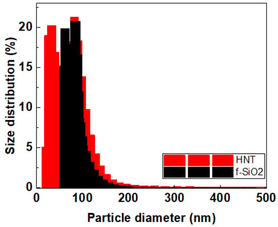
Figure 1.
Dynamic light-scattering (DLS) results obtained for HNT and functionalized silica.
TEM bright-field images of the silica nanoparticles and Halloysite nanotubes are shown in Figure 2. The dispersed silica nanoparticles, as shown in the low magnification Figure 2a and high magnification Figure 2b, indicate a nearly uniform size range of 10–25 nm. The obtained HNTs indicate the multiwalled nature of the tubes, as shown in Figure 2d. The multi-walled HNT has a length of 600 nm, with an outer diameter of 48 nm and inner diameter of 13 nm.
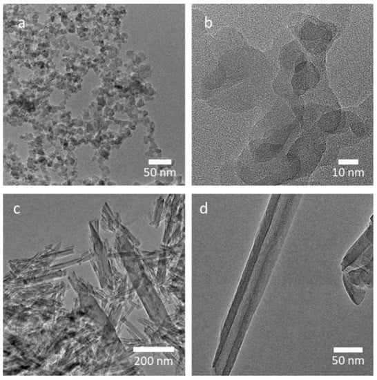
Figure 2.
TEM micrographs of the (a,b) silica and (c,d) HNT nanomaterials.
3.2. The Effects of Nanoparticle Nature on WCA and Transmittance with and without Thermal Curing
To understand the effect of the silica nanoparticles’ nature on the coating’s transmittance and wettability, three of the following coatings were compared: sol–gel, sol–gel + HNT, and sol–gel + f-SiO2. From Figure 3, we can observe that the sol–gel and sol–gel + HNT coatings remain hydrophilic before and after thermal treatment. However, the sol–gel + f-SiO2 is superhydrophobic before and after heat treatment. This may be due to the air trapped in the rough surface when water is dropped onto it. According to Cassie-Baxter, a smaller particle’s surface area interacting with water will result in a more significant contact angle. Chemically, polar molecules at the surface impacted wettability, causing an attraction between surface molecules and polar H2O [28]. As seen in Figure 3, the contact angle steadily increases with post-heat temperature. This combination’s effectiveness is primarily due to the practical surface shape and chemistry’s synergistic interaction. The main chemical adsorption occurred between the carboxyl groups of airborne organic molecules and the hydroxyl groups on the surface. In the meantime, the physical adsorption of airborne organic compounds on the surface may also be influenced by the hydrogen connection between the ester groups in those compounds and the hydroxyl groups. It has been widely reported that the apparent contact angle will decrease as the solid surface roughness increases, and the hydrophilicity is better when the solid surface is hydrophilic (contact angle 90°). When the solid surface is rough, the apparent contact angle will rise if the solid surface is hydrophobic (contact angle > 90°) [29]. In conclusion, the wettability change is due to both the chemistry and roughness of the films.
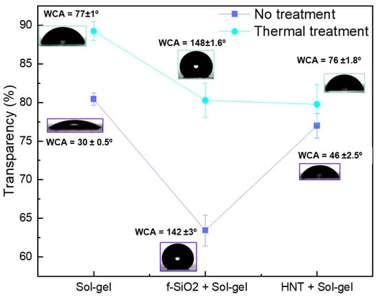
Figure 3.
Coatings’ transmittance and WCA images without and with thermal treatment.
3.3. The Effects Chemical Composition on WCA and Transmittance
To better investigate the chemical nature of the change in wettability on different silica-based coating, XPS measurements were carried out on sol–gel, sol–gel + HNT, and sol–gel + f-SiO2 samples. As seen in the survey spectra in Figure 4 and the atomic composition in Table 1, the three main components are C, O, and Si. Three peaks of the XPS spectra at 99, 110, 285, and 532 eV represent signals of binding energies for Si2s, Si2p, C1s, and O1s, respectively. The %Si increases from 24% in the sol–gel sample to 30% and 38% for the sol–gel + HNT and sol–gel + SiO2, respectively. It has been reported previously that Si-based components increased the hydrophobity of the films [30,31]. The aluminol groups on the surface of HNT could not be detected for two reasons: the sol–gel method and the depth of the analyzed area by XPS (XPS can only examine the outermost layer).
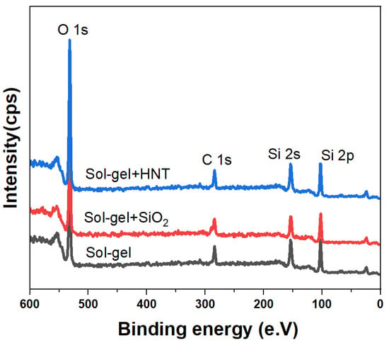
Figure 4.
X-ray photoelectron spectroscopy (XPS) survey spectrum of sol–gel, sol–gel + SiO2, and sol–gel + HNT.

Table 1.
Atomic percentage determined by XPS for sol–gel, sol–gel-HNT, and sol–gel + SiO2.
C1s peaks of sol–gel, sol–gel + HNT, and sol–gel + SiO2 with a Gaussian-curve fitting point out chemically different C species(see Figure 5). Two typical peaks are located at 284.6 and 285.7 eV, which are usually assigned to adventitious carbon, sp2-hybridized carbon, and the oxygen-containing carbonaceous bonds (C–OH) [32]. The sharp peak at positions 286 and 288 could be attributed to C = O and O = C–O [30]. However, the C1s from sol–gel + SiO2 is deconvoluted into two O–Si–C-only peaks. This suggests that the surface is covered by SiO2 particles. The deconvolution of Si 2p spectra shows two main components with different corresponding percentages to the Si-O-C bond (Silicon oxycarbide) at 103.0 eV and Si-O bond at 103.7 eV [33,34,35].
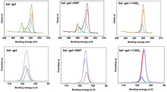
Figure 5.
High-resolution XPS spectra of the C1s and Si 2p core level for sol–gel, sol–gel + HNT, and sol–gel + f-SiO2.
3.4. The Effects of the f-SiO2 Concentration on WCA and Transmittance
Samples of different concentrations of f-SiO2 were prepared. Samples were designated according to their concentrations. The main properties, as well as the optical and surface properties, were analyzed using the transmittance and the water contact angle (WCA) of the samples. The WCA shown is the average angle for the three different spots on the sample surface. Figure 6 displays the average transmittance of the coating against the content of f-SiO2. Figure 6 illustrates that as the content of f-SiO2 in the coating increases from none to 100%, the corresponding WCA increases from hydrophilic of WCA = 30° to superhydrophobic of WCA = 158°. Furthermore, the average transmittance decreases from 80.4% at 0% f-SiO2 to 50% at 100% f-SiO2 content. It is known that the surface wettability is influenced by various physical and chemical factors. The impact of two key variables—surface roughness and surface chemistry—on contact angle measurements has been widely reported [36]. Here, in the current study, the Si content is increasing, so the surface chemistry is changing. As previously reported in the XPS section, increasing the Si content will result in more hydrophobic behavior. However, this wettability change is accompanied by a change in the surface transmittance caused by the white color of f-SiO2. Therefore, for self-cleaning the transparent panel, the optimal content of the nanoparticle would be 70%, because this content would result in the optimal balance between the optical properties and the surface properties, enabling acceptable transmittance and high WCA.
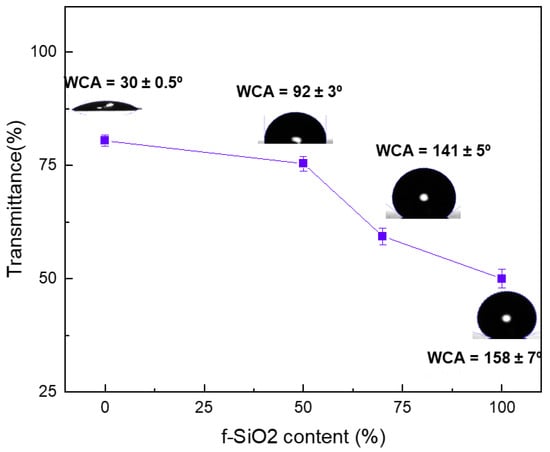
Figure 6.
The value of average transmittance of the coating varies with the content of f-SiO2 with the corresponding WCA images and values.
3.5. The Effect of Spraying Parameters
- a.
- Distance between the nozzle and substrate
The critical particle velocity, which depends on particle characteristics, such as density and size, is the most crucial element in the spray process that influences coating development. The particles continue accelerating as they leave the nozzle throughout the cold-spray procedure. In this regard, substrate–nozzle distance is crucial and needs to be optimized. Shock waves arise on the substrate surface when the nozzle–substate distance exceeds the critical value, which results in a decrease in velocity. The particle’s velocity will drop if the distance exceeds the critical value. Figure 7 shows a schematic illustration of the nozzle substrate distance.

Figure 7.
Schematic illustration of the substrate–nozzle distance.
Figure 8 displays the WCA and transmittance of the as-sprayed coatings at various spraying distances illustrated Figure 7 and with varying f-SiO2 contents. As the spraying distance increases, the coating’s WCA for a given f-SiO2 percentage stays constant. However, the transmittance changes significantly as you get closer to the nozzle and surface. It is known that the farther the nozzle is from the top surface of the substrate, the higher the porosity of the sprayed coatings, so the WCA decreases. At a higher distance, the deformation of a particle is determined by its strength and density, which will influence the particle’s kinetic energy at the same velocity [36]. Therefore, it is difficult to form a dense coating due to its low density [37,38]. However, for our coatings, the results showed that only the f-SiO2 content influences the surface reactivity. This can explain why the coating with the same f-SiO2 content was less transparent but with approximately the same WCA and a relatively high deposition efficiency.
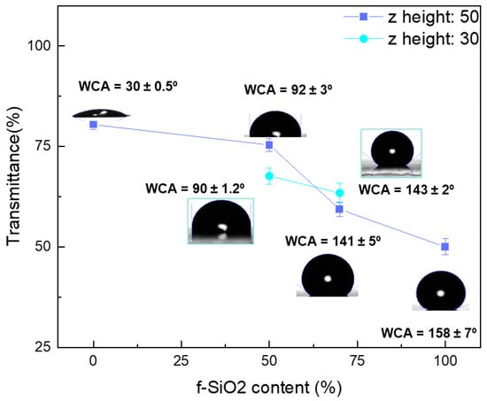
Figure 8.
Value of average transmittance of the coating varies with the content of f-SiO2 the with the corresponding WCA images at two different spraying distances—30 mm and 50 mm.
- b.
- Shaping air pressure
The used AccuMist nozzle system creates a soft, sharply focused beam of tiny spray drops by combining low-pressure air with an ultrasonic atomizing nozzle. A uniform flow of compressed air is built around the nozzle stem by introducing compressed air into the diffusion chamber of an air shroud, which surrounds the nozzle and is typically compressed at 3 psi (see Figure 9). The low-pressure air stream immediately incorporates the ultrasonically created spray at the stem’s tip. The air shroud’s focusing mechanism can be adjusted to provide total control over spray width. The spray container has an hourglass-like form and is very narrow. The results shown in Figure 10 demonstrate that for the exact content of f-SiO2, the transmittance and WCA are higher when using higher-shaping air. The liquid droplets tend to follow, molding air to diverge radially and producing higher overspray under high rotating speeds and low-shaping air-flow conditions. The smaller droplets that follow the air with a strong forward momentum will produce a more concentrated spray and better conveyance at high rotating speeds and high-shaping air flow [39,40].
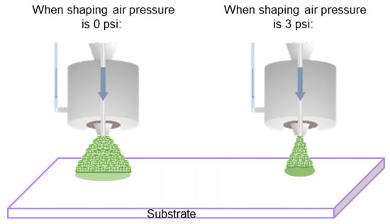
Figure 9.
Schematic illustration of the resulting flow (left) without shaping air and (right) with shaping air.
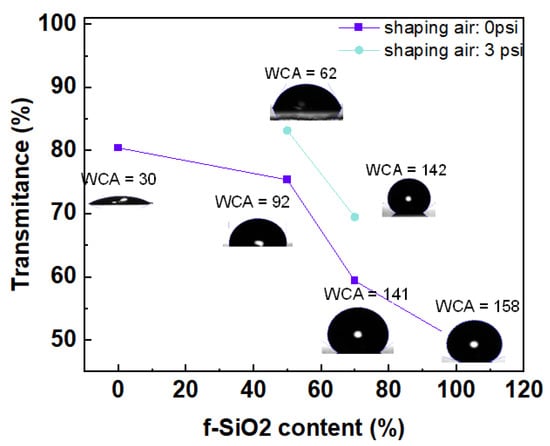
Figure 10.
Value of average transmittance of the coating varies with the content of f-SiO2, the corresponding WCA images, and the values of samples sprayed with shaping air of 0 psi and 3 psi.
- c.
- Area spacing
In the spray process, the area spacing substantially impacts the coating profile. The area spacing is defined as the distance of two neighbor scanning passes (Figure 11). In our experiment, we tested the effect of different area spacing on the WCA and the transmittance of the resulting coatings. The results are depicted in Figure 12.
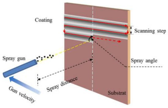
Figure 11.
Schematic demonstration of the area spacing.
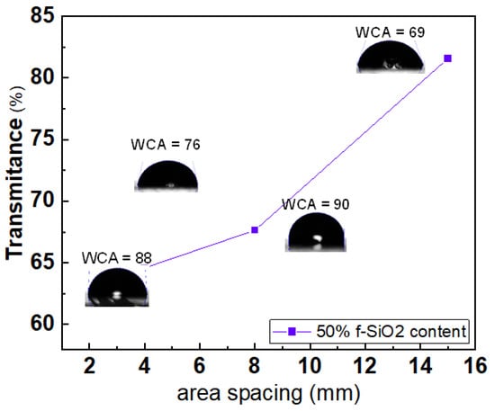
Figure 12.
Value of average transmittance of the coating varies with the area spacing in mm with the corresponding WCA images and values.
Two different ranges are seen: where the area spacing is favorable, and the inverse. The WCA is almost hydrophobic for very low area spacing. This is due to the total coverage of the surface by the silica-based coating that we previously demonstrated, which is hydrophobic. The film became more transparent when the area spacing is higher than 8 mm; however, the WCA decreases drastically from 90° to 69°. Obviously, the surface covered by the silica-based coating decreased, thus resulting in a decrease in the WCA. The same effect was observed by Han et al. [39].
4. Conclusions
This paper investigated a simple method of producing coatings with different wettability and transparency. Firstly, different silica-based mixtures were investigated. The sol–gel + f-SiO2 gives the best WCA and transparency results. The XPS measurement demonstrated the high content of the functionalized silica in the sol–gel + f-SiO2 coating. The superhydrophobic behavior of this composition is primarily reported. In the second section of the paper, the spraying parameters of the ultrasound spray coater, namely standoff distance, shaping air pressure, and area spacing, were investigated. As a result, coatings were applied to the glass substrate during the cold-spraying process while varying the spay-coater parameters. The findings indicate that increasing the distance between the nozzle and surface has a favorable impact on the coating attributes, particularly coating transparency and WCA. Increasing shaping air positively affects the coating qualities, especially the WCA. Lastly, increasing the area spacing results in better WCA and transparency until a critical value is reached, where transparency is improved but hydrophobicity is lost. The findings of this research can be considered as a step toward reaching a superhydrophobic self-cleaning surface that could be used in different applications such as: PV panels, aerospace, biomedical applications, and buildings. For future research directions, studies concerning surface ageing and UV resistance should be applied to upscale these results.
Author Contributions
Conceptualization, S.A. and Z.M.; methodology, Z.M.; software, S.A. and A.A.; validation, Z.M., S.A. and M.G.; formal analysis, Z.M.; investigation, Z.M.; data curation, Z.M.; writing—original draft preparation, S.A. and Z.M.; writing—review and editing, S.A., Z.M., N.R., M.M., A.A. and M.G. supervision, M.G. and Z.M. All authors have read and agreed to the published version of the manuscript.
Funding
This research received no external funding.
Institutional Review Board Statement
Not applicable.
Informed Consent Statement
Not applicable.
Data Availability Statement
Data available upon request.
Conflicts of Interest
The authors declare no conflict of interest.
References
- Verduci, R.; Romano, V.; Brunetti, G.; Yaghoobi Nia, N.; Di Carlo, A.; D’Angelo, G.; Ciminelli, C. Solar Energy in Space Applications: Review and Technology Perspectives. Adv. Energy Mater. 2022, 12, 2200125. [Google Scholar] [CrossRef]
- Sharma, B.; Sachithanandam, S.; Taahir, M.; Bintang, S.; Muhammad Aulia, R.S.; Haryanto Sinaga, D.; Sugiartha, N.; Ardana, I.G.N.; Sugina, I.M.; Widiantara, I.B.G.; et al. Preliminary design and test of a water spray solar panel cleaning system You may also like Effect of Nanosilica and Multiwalled Carbon Nanotubes on the Mechanical and Impact Performance of Unidirectional Kevlar/Epoxy Based Composites The effect of reflector application for solar panel output improvement Preliminary design and test of a water spray solar panel cleaning system. J. Phys. Conf. Ser. 2020, 1450, 12108. [Google Scholar]
- Gupta, V.; Sharma, M.; Pachauri, R.K.; Dinesh Babu, K.N. Comprehensive review on effect of dust on solar photovoltaic system and mitigation techniques. Sol. Energy 2019, 191, 596–622. [Google Scholar] [CrossRef]
- Mozumder, M.S.; Mourad, A.H.I.; Pervez, H.; Surkatti, R. Recent developments in multifunctional coatings for solar panel applications: A review. Sol. Energy Mater. Sol. Cells 2019, 189, 75–102. [Google Scholar] [CrossRef]
- Lu, H.; Zheng, C.; Diamanti, M.V.; Lu, H.; Zheng, C. Comparison of Dust Deposition Reduction Performance by Super-Hydrophobic and Super-Hydrophilic Coatings for Solar PV Cells. Coatings 2022, 12, 502. [Google Scholar] [CrossRef]
- Zorrilla-Casanova, J.; Piliougine, M.; Carretero, J.; Bernaola-Galván, P.; Carpena, P.; Mora-Lõpez, L.; Sidrach-De-Cardona, M. Losses produced by soiling in the incoming radiation to photovoltaic modules. Prog. Photovoltaics Res. Appl. 2013, 21, 790–796. [Google Scholar] [CrossRef]
- Castro-Hoyos, A.M.; Rojas Manzano, M.A.; Maury-Ramírez, A. Challenges and Opportunities of Using Titanium Dioxide Photocatalysis on Cement-Based Materials. Coatings 2022, 12, 968. [Google Scholar] [CrossRef]
- He, Q.; He, W.; Zhang, F.; Zhao, Y.; Li, L.; Yang, X.; Zhang, F. Research Progress of Self-Cleaning, Anti-Icing, and Aging Test Technology of Composite Insulators. Coatings 2022, 12, 1224. [Google Scholar] [CrossRef]
- Kurbanova, A.; Myrzakhmetova, N.; Akimbayeva, N.; Kishibayev, K.; Nurbekova, M.; Kanagat, Y.; Tursynova, A.; Zhunussova, T.; Seralin, A.; Kudaibergenova, R.; et al. Superhydrophobic SiO2/Trimethylchlorosilane Coating for Self-Cleaning Application of Construction Materials. Coatings 2022, 12, 1422. [Google Scholar] [CrossRef]
- Wang, L.; Guo, X.; Zhang, H.; Liu, Y.; Wang, Y.; Liu, K.; Liang, H.; Ming, W. Recent Advances in Superhydrophobic and Antibacterial Coatings for Biomedical Materials. Coatings 2022, 12, 1469. [Google Scholar] [CrossRef]
- Syafiq, A.; Pandey, A.K.; Adzman, N.N.; Rahim, N.A. Advances in approaches and methods for self-cleaning of solar photovoltaic panels. Sol. Energy 2018, 162, 597–619. [Google Scholar] [CrossRef]
- Kawamoto, H. Electrostatic cleaning equipment for dust removal from soiled solar panels. J. Electrostat. 2019, 98, 11–16. [Google Scholar] [CrossRef]
- Altıntaş, M.; Arslan, S. The Study of Dust Removal Using Electrostatic Cleaning System for Solar Panels. Sustainability 2021, 13, 9454. [Google Scholar] [CrossRef]
- Calle, C.I.; Buhler, C.R.; McFall, J.L.; Snyder, S.J. Particle removal by electrostatic and dielectrophoretic forces for dust control during lunar exploration missions. J. Electrostat. 2009, 67, 89–92. [Google Scholar] [CrossRef]
- Kawamoto, H.; Shibata, T. Electrostatic cleaning system for removal of sand from solar panels. J. Electrostat. 2015, 73, 65–70. [Google Scholar] [CrossRef]
- Santosh Kumar, S.; Shankar, S.; Murthy, K. Solar Powered PV Panel Cleaning Robot. In Proceedings of the 5th IEEE Interna-tional Conference on Recent Trends in Electronics, Information and Communication Technology (RTEICT), Bangalore, India, 12–13 November 2020; Volume 2020, pp. 169–172. [Google Scholar] [CrossRef]
- Parrott, B.; Carrasco Zanini, P.; Shehri, A.; Kotsovos, K.; Gereige, I. Automated, robotic dry-cleaning of solar panels in Thuwal, Saudi Arabia using a silicone rubber brush. Sol. Energy 2018, 171, 526–533. [Google Scholar] [CrossRef]
- Askar, K.; Phillips, B.M.; Fang, Y.; Choi, B.; Gozubenli, N.; Jiang, P.; Jiang, B. Self-assembled self-cleaning broadband anti-reflection coatings. Colloids Surfaces A Physicochem. Eng. Asp. 2013, 439, 84–100. [Google Scholar] [CrossRef]
- Xu, Q.; Zhao, Q.; Zhu, X.; Cheng, L.; Bai, S.; Wang, Z.; Meng, L.; Qin, Y. A new kind of transparent and self-cleaning film for solar cells. Nanoscale 2016, 8, 17747–17751. [Google Scholar] [CrossRef]
- Ren, T.; He, J. Substrate-versatile approach to robust antireflective and superhydrophobic coatings with excellent self-cleaning property in varied environments. ACS Appl. Mater. Interfaces 2017, 9, 34367–34376. [Google Scholar] [CrossRef]
- Sutha, S.; Suresh, S.; Raj, B.; Ravi, K.R. Transparent alumina based superhydrophobic self–cleaning coatings for solar cell cover glass applications. Sol. Energy Mater. Sol. Cells 2017, 165, 128–137. [Google Scholar] [CrossRef]
- Adak, D.; Bhattacharyya, R.; Saha, H.; Maiti, P.S. Sol–gel processed silica based highly transparent self-cleaning coatings for solar glass covers. Mater. Today Proc. 2020, 33, 2429–2433. [Google Scholar] [CrossRef]
- Zhang, C.; Kalulu, M.; Sun, S.; Jiang, P.; Zhou, X.; Wei, Y.; Jiang, Y. Environmentally safe, durable and transparent superhydrophobic coating prepared by one-step spraying. Colloids Surf. A Physicochem. Eng. Asp. 2019, 570, 147–155. [Google Scholar] [CrossRef]
- Crick, C.R.; Parkin, I.P. A single step route to superhydrophobic surfaces through aerosol assisted deposition of rough polymer surfaces: Duplicating the lotus effect. J. Mater. Chem. 2009, 19, 1074–1076. [Google Scholar] [CrossRef]
- Langlet, M.; Vautey, C.; Mazeas, N. Some aspects of the aerosol–gel process. Thin Solid Films 1997, 299, 25–32. [Google Scholar] [CrossRef]
- Alam, K.; Ali, S.; Saboor, A.; Salman, M.; Maoz; Humayun, M.; Sadiq, M.; Arif, M. Antireflection, Superhydrophilic Nano-Porous SiO2 Coating based on Aerosol Impact Spray Deposition Technique for Solar PV Module. Coatings 2019, 9, 497. [Google Scholar] [CrossRef]
- Benti, N.E.; Aneseyee, A.B.; Asfaw, A.A.; Geffe, C.A.; Tiruye, G.A.; Mekonnen, Y.S. Estimation of global solar radiation using sunshine-based models in Ethiopia. Civ. Environ. Eng. 2022, 9. [Google Scholar] [CrossRef]
- Di, Y.; Qiu, J.; Wang, G.; Wang, H.; Lan, L.; Zheng, B. Exploring Contact Angle Hysteresis Behavior of Droplets on the Surface Microstructure. Langmuir 2021, 37, 7078–7086. [Google Scholar] [CrossRef]
- Li, C.; Zhang, J.; Han, J.; Yao, B. A numerical solution to the effects of surface roughness on water–coal contact angle. Sci. Rep. 2021, 11, 459. [Google Scholar] [CrossRef]
- Matouk, Z.; Rincón, R.; Torriss, B.; Mirzaei, A.; Margot, J.; Dorris, A.; Beck, S.; Berry, R.M.; Chaker, M. Functionalization of cellulose nanocrystal powder by non-thermal atmospheric-pressure plasmas. Cellulose 2021, 28, 6239–6252. [Google Scholar] [CrossRef]
- Matouk, Z.; Torriss, B.; Rincón, R.; Dorris, A.; Beck, S.; Berry, R.M.; Chaker, M. Functionalization of cellulose nanocrystal films using Non-Thermal atmospheric –Pressure plasmas. Appl. Surf. Sci. 2020, 511, 145566. [Google Scholar] [CrossRef]
- Smith, M.; Scudiero, L.; Espinal, J.; McEwen, J.S.; Garcia-Perez, M. Improving the deconvolution and interpretation of XPS spectra from chars by ab initio calculations. Carbon N. Y. 2016, 110, 155–171. [Google Scholar] [CrossRef]
- Zakhvalinskii, V.; Piliuk, E.; Goncharov, I.; Simashkevich, A.; Sherban, D.; Bruc, L.; Curmei, N.; Rusu, M. Silicon carbide nanolayers as a solar cell constituent. Phys. Status Solidi Appl. Mater. Sci. 2015, 212, 184–188. [Google Scholar] [CrossRef]
- Gao, D.; Wijesundara, M.B.J.; Carraro, C.; Maboudian, R.; Howe, R.T. Characterization of residual strain in SiC films deposited using 1,3-disilabutane for MEMS application. J. Microlithogr. Microfabr. Microsystems 2003, 2, 259–264. [Google Scholar] [CrossRef]
- Kaur, A.; Chahal, P.; Hogan, T. Selective fabrication of SiC/Si diodes by excimer laser under ambient conditions. IEEE Electron Device Lett. 2016, 37, 142–145. [Google Scholar] [CrossRef]
- Chau, T.T.; Bruckard, W.J.; Koh, P.T.L.; Nguyen, A.V. A review of factors that affect contact angle and implications for flotation practice. Adv. Colloid Interface Sci. 2009, 150, 106–115. [Google Scholar] [CrossRef]
- Li, W.Y.; Zhang, C.; Guo, X.P.; Zhang, G.; Liao, H.L.; Li, C.J.; Coddet, C. Effect of standoff distance on coating deposition characteristics in cold spraying. Mater. Des. 2008, 29, 297–304. [Google Scholar] [CrossRef]
- Żórawski, W.; Molak, R.; Mądry, J.; Sienicki, J.; Góral, A.; Makrenek, M.; Scendo, M.; Dobosz, R. Experimental and Numerical Investigations of Titanium Deposition for Cold Spray Additive Manufacturing as a Function of Standoff Distance. Materials 2021, 14, 5492. [Google Scholar] [CrossRef]
- Cai, Z.; Deng, S.; Liao, H.; Zeng, C.; Montavon, G. The Effect of Spray Distance and Scanning Step on the Coating Thickness Uniformity in Cold Spray Process. J. Therm. Spray Technol. 2013, 23, 354–362. [Google Scholar] [CrossRef]
- Li, W.; Qian, L.; Song, S.; Zhong, X. Numerical Study on the Influence of Shaping Air Holes on Atomization Performance in Pneumatic Atomizers. Coatings 2019, 9, 410. [Google Scholar] [CrossRef]
Disclaimer/Publisher’s Note: The statements, opinions and data contained in all publications are solely those of the individual author(s) and contributor(s) and not of MDPI and/or the editor(s). MDPI and/or the editor(s) disclaim responsibility for any injury to people or property resulting from any ideas, methods, instructions or products referred to in the content. |
© 2023 by the authors. Licensee MDPI, Basel, Switzerland. This article is an open access article distributed under the terms and conditions of the Creative Commons Attribution (CC BY) license (https://creativecommons.org/licenses/by/4.0/).