Article

Development of Novel Semi-Stranded Windings for High Speed Electrical Machines Enabled by Additive Manufacturing

by
Ahmed Selema
1,2,3,*,
Mohamed N. Ibrahim
1,2,4 and
Peter Sergeant
1,2
1
Department of Electromechanical, Systems, and Metal Engineering, Ghent University, 9000 Ghent, Belgium
2
FlandersMake@UGent, Core Lab EEDT-MP, 3001 Leuven, Belgium
3
Department of Electrical Engineering, Faculty of Engineering, Menoufia University, Menoufia 32511, Egypt
4
Department of Electrical Engineering, Kafrelshiekh University, Kafrelshiekh 33511, Egypt
*
Author to whom correspondence should be addressed.
Appl. Sci. 2023, 13(3), 1653; https://doi.org/10.3390/app13031653
Submission received: 7 January 2023 / Revised: 25 January 2023 / Accepted: 27 January 2023 / Published: 28 January 2023

Abstract

:
Recent advances in electrical machines and energy storage technologies make electric vehicles (EVs) feasible replacements to conventional internal combustion engines. One of the main challenges of high speed electrical machines is providing maximum output power with minimum energy losses, weight, and volume. At high frequency operation, the conductors of AC electrical machines can suffer from skin and proximity effects. This results in high AC losses in the machine windings and can eventually lead to machine failure. In this paper, a novel design for a semi-stranded coil is proposed to limit these undesirable effects. Enabled by additive manufacturing (AM) technology, this sophisticated design is 3D printed using ultralight aluminum alloy. Finally, the AC performance of this coil is measured and compared with conventional single-strand copper coil at different frequency levels. It is found that the proposed design can effectively limit the eddy current losses in the high frequency domain.

1. Introduction

The new challenge for electric vehicle (EV) manufacturers is ’1000 km on a single charge’ [1]. To overcome this challenge, not only an efficient energy storage system is required, but also an efficient electric machine. That is why interest in electric machines with high power density is increasing remarkably. Combining the merits of high efficiency, lightweight, and compactness is essential for the design of such machines. One of the common strategies to increase the machine output power per volume is to increase the rotational speed. However, beside mechanical challenges (i.e., lubrication, vibrations, robustness, bearings), this can also result in an increase in electrical losses per volume. The main reason is that high frequency operation causes extra winding losses and iron losses. Therefore, using low loss materials is essential for the manufacturing of energy-efficient electrical machines.
Machine windings are identified as the main hotspot inside an electrical machine. They are the root cause for most failures in electrical machines. At high speed operation, high electromagnetic stress is applied on the stator coils. In fact, one of the major problems of the resulting high frequency is the excessive AC conduction losses that can lead to a reduced life time of the windings and the machine. Basically, when the stator conductors are surrounded by the ferromagnetic teeth, the conductors are exposed to a high magnetic field, which causes extra eddy current losses within each turn. Typically, to overcome this problem, stranded or litz windings are used for the armature windings [2,3,4].
Stranded windings are the ideal affordable choice for cramped spaces and almost all slot shapes. On the other hand, one of the main disadvantages of such wires is that they usually have a minimum bending radius of four times their outer diameter. So, when utilizing such wires, it is expected that the overhang will be long in spite of their superior bendability, especially if there is an overlap between windings.
For a further improvement of the performance of stranded wires at high frequencies, the strands transposition can be considered one of the helpful solutions to reduce the eddy current losses in the conductors. With insulated and twisted sub-strands, litz windings can effectively limit the high-frequency eddy current losses and circulating currents. However, using fully stranded coils is not the optimal solution for the above-mentioned issue because of two main reasons. The first reason is that the fill factor of the stranded coils is very low compared to other types of magnet wires (e.g., rectangular hairpins). As a result, the DC losses are much higher. The second reason is that stranded wires are usually placed randomly inside the stator slot, and it is extremely hard to control the strand location. This can eventually result in higher AC losses than expected.
On the counterpart, using a single strand coil with flat conductors can guarantee a high fill factor and low DC resistance. However, the skin effect and AC losses will be too high. Flat hairpin conductors can fit in a rectangle closed or semi-closed slot. However, a post-process of welding is necessary to join the hairpins. This time consuming process can cause a delay in the supplier chain specially. Alternatively, a radially-inserted flat conductor coil can be used with a single continuous conductor. Yet, an open slot design is required. The disadvantages of flat solid conductor include the high cost and the less mechanical flexibility. They cannot also fit in different slot shapes. Besides, there are excessive AC losses at high frequencies.
This study is aiming to find effective solutions for the aforementioned issues by combining between the reduced AC losses of stranded windings and the high fill factor of single-strand windings. This is achieved by adopting a new design concept of “semi-stranded coil” with half-solid half-stranded conductors. Additionally, the strands’ locations are controlled and transposed to minimize the AC losses in this coil. Combining between the design novelty, controlled strand positioning, and ultralight weight structure, is only possible using a flexible and unique technology such as additive manufacturing (AM). To the best of the authors’ knowledge, there is no published work concerning 3D printed stranded windings with such structure, especially for high speed electrical machines.
The paper is divided as follows. Section 2 is outlining the potentials and recent developments in the 3D printing of electrical machines and the windings in particular. In Section 3, a new concept of semi-stranded windings is introduced and different possibilities are simulated using finite element modeling (FEM). Section 4 is devoted to the prototyping and experimentation of this novel topology. Additionally, the AC losses are measured and compared with the conventional winding topologies. In Section 5, the thermal performance of the proposed windings is analyzed. Finally, Section 6 highlights the main conclusions and findings of this study.

2. Additive Manufacturing for Electrical Machines Windings

Additive manufacturing (AM) of electrical machines has been explored in different studies [5,6,7,8,9]. New families of electrical machines are manufactured, which were difficult to be built using conventional methods [10,11,12,13]. Yet, utilizing AM in building the active parts, such as core or windings, is still limited. In such parts, not only improving the mechanical properties is required, but also the electromagnetic properties’ enhancement is mandatory.
This technology can also allow printing different conducting materials using different AM techniques [14,15,16]. This includes electron beam melting (EBM) of copper powder [17], the selective laser melting (SLM) of copper [18], aluminum [19,20], and silver [21], and 3D micro-extrusion of copper and aluminum [22,23]. However, in most of these attempts, only thin conductors are built without considering complete coil structures. Typically, copper is the common choice for electrical machine windings because of its high electrical and thermal conductivities. On the counterpart, aluminum has relatively lower electrical and thermal conductivities, but it has only 30% of the weight of copper. Additionally, the higher resistivity of aluminum can be beneficial to limit high frequency eddy current losses. So, aluminum can be an effective alternative to copper for high speed electrical machines and weight sensitive applications.
Using AM technology, it is also possible to integrate direct cooling channels inside the slot for better thermal performance. Hollow conductors can also be printed with imbedded cooling path for liquid in each turn. An example is investigated in [24]. In this study, 3D printed coils are prototyped using different material alloys (copper and aluminum). Both cases have the exact same design with integrated direct cooling channels. With the proposed approach, the maximum current density is boosted to high levels. Accordingly, the machine power density has also improved significantly.
In [25], the AM of shaped profile windings is introduced for minimal AC loss in electrical machines. The main concept is to print the conductors with a profile that is parallel to the slot leakage flux. As a result, minimum interaction between the conductor and the flux is achieved and the losses is minimized. According to the authors, these shaped profile coils have the potential for improving efficiency in different applications such as electric vehicle traction, automotive applications, and aerospace propulsion.
In [26], a new design of complete coil is introduced with uneven layers as shown in Figure 1. In this design, the turns near the slot opening have lower height compared to the turns at the slot bottom. As a results, the impact of the cross slot leakage flux is limited and the losses in the upward turns is effectively reduced. Additionally, the cross section area has a z-shaped profile to guarantee a uniform distribution of the current density. The aforementioned coil is printed using aluminum alloy to provide additional limitation to eddy current losses at high speed operation. The coil has also 74% lower weight compared to a conventional copper coil. Despite its good performance at high frequency, this coil is printed with single strand turns. To consider a multi strand coil, more degrees of freedom are required.
To conclude, the adoption of advanced techniques such as 3D printing expands the design space available and could afford significant performance improvements and enhanced thermal management. In this paper, one of the targets is to enable AM technology to print a complete 3D coil with a more sophisticated design. In this design, the dimensional freedom of AM can allow for a multi strand coil with low AC losses. Additionally, the strands’ locations are transposed to minimize the eddy current losses at high frequency. The only one problem of a fully stranded coil is that it has a low fill factor and a higher DC resistance. With that being said, a new concept of a semi-stranded coil is introduced as explained in the following section.

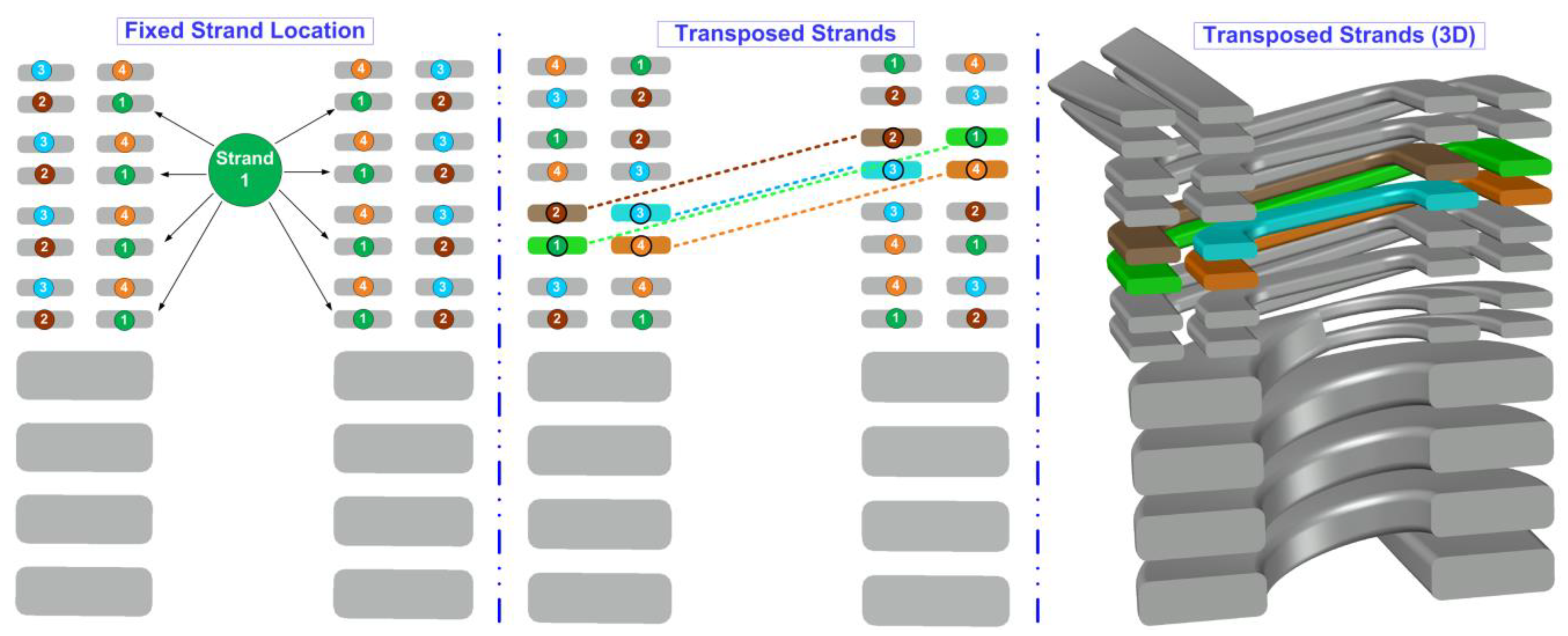
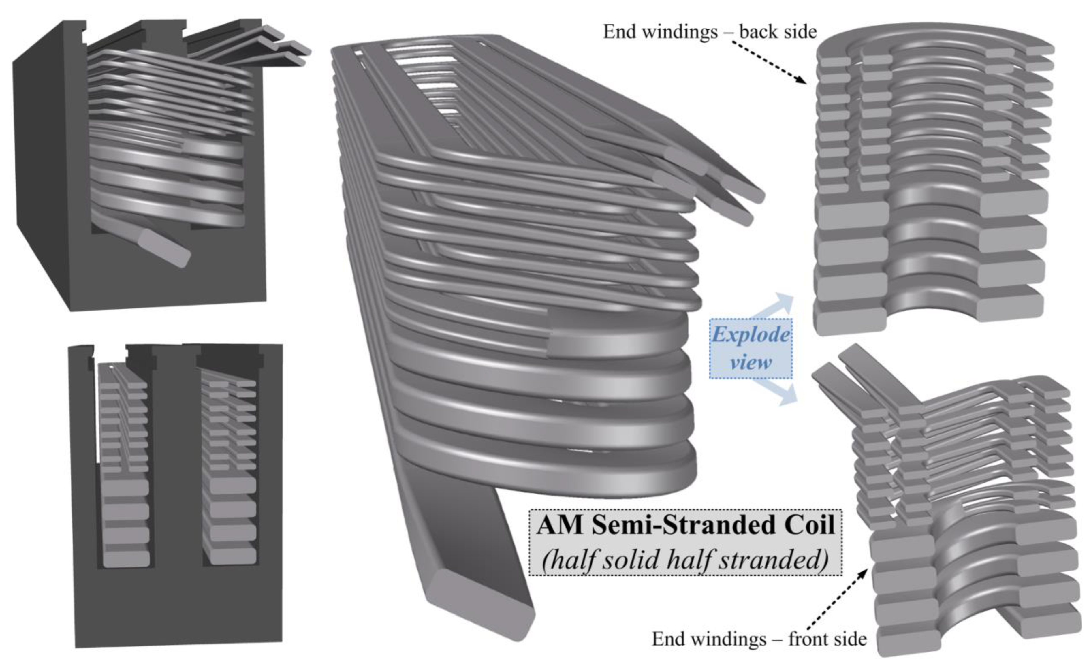
3. Semi-Stranded Coils: A New Concept

To combine high fill factor and high AC performance, a novel semi-stranded coil is proposed. In this design, the lower half of the coil has a single strand, and the upper half has multi-strands. The main reason is that the upper turns (i.e., near the slot opening) are more exposed to leakage flux, and they possess over 70% of the total AC losses [27]. Additionally, unlike coils with randomly placed strands, a controlled strand positioning is enabled using AM. This means that each strand has a well-defined location inside the stator slot, which allows for an accurate finite element simulation.
In order to demonstrate the concept of the semi-stranded coil, the electromagnetic performances of five case studies are investigated, as shown in Figure 2. As can be noticed, Coil 1 is the reference coil case which represents the conventional approach of rectangular windings. In this design, eight flat solid copper conductors are used per slot. Coil 2 is a semi-stranded coil with the upper three turns divided into two strands. Coil 3 is a semi-stranded coil with the upper four turns divided into four strands with fixed locations. Coil 4 is similar to Coil 3, except for using different strand positions.
The concept of strand transposition is compared with the fixed strand location, as shown in Figure 3. The strands of the four upper turns are transposed so that each strand moves one location when going to the next turn. The design of the end turns in 3D is very compact and precise especially at the front end of the coil (Figure 3). The one of a kind design allows for a smooth and continuous transition between the series turns.
Coil 5 is identical in the design of Coil 4; however, an aluminum material is used instead of copper. The main target is to compare the performance of these materials at high frequency under the same geometries. The electrical circuit of Coils 3-5 is shown in Figure 4. As can be seen, the first four turns have a single conductor and are carrying the same current. On the top four turns, each turn has four strands. The strands in the positive and negative slots are electrically connected. For a fair comparison between all cases, the same slot geometries are used for all the designs. Additionally, all the designs are simulated under the same current level.
The current densities in the five designs are computed and compared at high frequency of 2 kHz, as shown in Figure 2. As can be seen, Coil 1 has the worst current density distribution. The main reason is that the turns are solid causing an excessive current density of 44.5A/mm2 at the upper turns. In Coils 2 and 3, the maximum current density is not reduced much due to using a fixed strand location. On the counterpart, Coils 4 and 5 have reduced the current density significantly by 43% and 63%, respectively. The aluminum coil (Coil 5) has a better current density distribution compared to the copper one (Coil 4). The main reason is that the aluminum has higher resistivity than copper, resulting in more limitation for the eddy current losses in the high frequency domain.
The losses are also calculated in each turn for all the five case studies at 2 kHz, as shown in Figure 5a. As can be noticed, in Coils 2 and 3, the losses are reduced by stranding in only turns 7.8. On the other hand, with the transposed strands in Coils 4 and 5, all the stranded turns have remarkably lower AC losses. Furthermore, the total AC losses are compared for all coil cases at different frequency levels, as shown in Figure 5b. It is clear that using the semi-stranded coil with transposed strand location can provide a remarkable performance starting from low frequencies (200 Hz). It is also obvious that using aluminum instead of copper can provide even lower losses above 1 kHz. With this being said, a semi-stranded aluminum coil is to be built using AM with transposed strand locations.

4. Thermal Performance Comparison

In order to evaluate the thermal performance of the semi-stranded coil, the power losses should be estimated at different operating conditions and frequencies [28]. Then, the electromagnetic performance is coupled with a finite element thermal model to measure the temperature profile during one cycle of the Worldwide harmonized Light-duty vehicles Test Cycles (WLTC), shown in Figure 6. In the WLTC, the speed varies as a function of time. The WLTC cycle is divided into four parts with different top speed (Low, Medium, and High, Extra High). In each part, the speed has a certain fluctuating pattern with increasing and decreasing speeds. In the first part (Low), the top speed is about 55 km/h. In the second part (Medium), the top speed is about 75 km/h. In the third part (High), the top speed is nearly 100 km/h. In the final part (Extra high), the top speed is about 130 km/h. Based on the machine specifications and gear box ratio, the electrical frequency of the machine currents can be calculated. So, the higher the speed, the higher the frequency will become. The next step is to calculate the electromagnetic losses and export their values to a thermally coupled simulation. In the thermal simulation, the thermal conductivity of each material must be inserted to have a high level of accuracy. Additionally, to emulate a real machine, the cooling jacket side must be added to the simulation.
Using finite element thermal analysis, the maximum temperature value is calculated as a function of time as shown in Figure 7. As can be seen, at low and medium speeds, the maximum temperature in the semi-stranded coil rises relatively higher than that in the solid one. However, at high and extra-high speeds, the temperature in the semi-stranded coil starts to fall under the value in the solid coil. Under the same driving cycle (WLTC) and cooling conditions, the maximum temperature at the worst case scenario in the semi-stranded coil is 159.7 °C, which is significantly lower than its value in the solid coil (178.3 °C). This is also demonstrated in the thermal profile shown in Figure 8 at high frequency domain (i.e., extra-high speed). From this figure, it is noticed that the hot spot is located at upper two turns. This means that the cross slot leakage flux has high impact on the conventional solid conductor resulting in high AC losses. On the other hand, the hot spot of the semi-stranded coil is located nearly in the middle of the slot. This shows that the proposed approach has effectively limited the negative impact of the cross-slot leakage flux.
With this being said, it is concluded that the semi-stranded coil is less prone to failure compared to the conventional solid one under the worst heating scenarios.

5. Sample Preparation and Loss Measurement

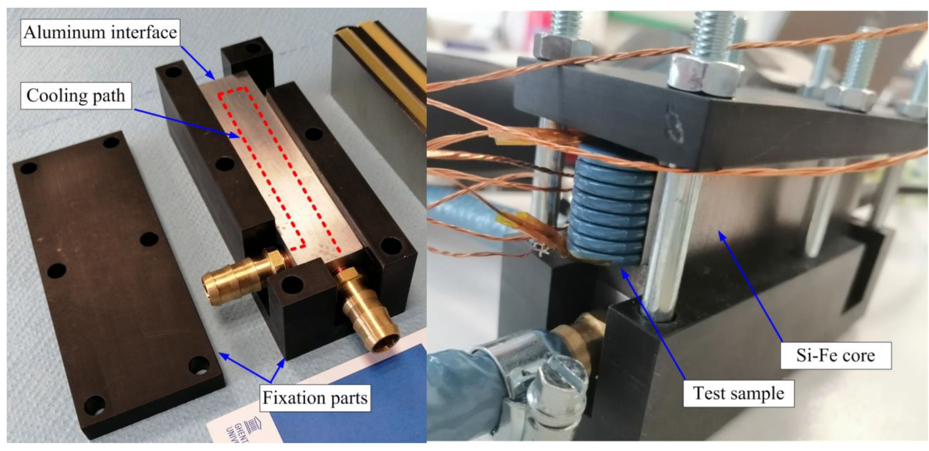
5.1. Sample Preparation

Using SLM, two coils are printed for the same slot geometries using two different materials. The technology SLM can accelerate the development of innovative customized components. Additionally, it can allow for material optimization in order to reduce raw material consumption.
In the first prototyped sample, a single-strand coil is printed with eight flat solid turns using pure-copper, as shown in Figure 9. The gaps between the conductors are reduced so that the slot fill factor is increased to 77.96%. This remarkably high fill factor allows for reduced DC losses in this copper coil. The coil is then heat treated inside a controlled atmosphere chamber to relive any residual stress and to boost its electrical conductivity. Finally, the turns are insulated using epoxy resin that withstand a temperature up to 180 °C. The copper coil weight is 183.6 g. The electrical conductivity of the copper coil is measured compared to commercial copper. It is found that the printed copper coil has 100% IACS (International Annealed Copper Standard).
In the second prototyped sample, a semi-stranded coil is designed, as shown in Figure 10. The four upper turns are divided into four transposed strands. Unlike conventional transposed roebel bar, the strand transpositioning is ingeniously made at the coil front end winding (not inside the slot), as previously explained in Figure 3. As a result, a high fill factor of 70.6 is achieved. This fill factor is considered to be much higher than that in the conventional fully stranded coils, which is typically between 35–45%, as reported in [29]. The coil is 3D printed using SLM of aluminum alloy (AlSi10Mg), as shown in Figure 11. The coil has a perfect finishing with very precise dimensions. This material combines good conductivity and ultralight weight, which are suitable for high frequency machines. A post-process heat treatment is also used to enhance the electrical and mechanical properties. Finally, the strands and turns are electrically insulated using class H air-drying polyester varnish (Synthite AC-43 180 °C). The coil weight is 55.2 g, which is only 30.1% of the weight of the 3D printed copper coil.

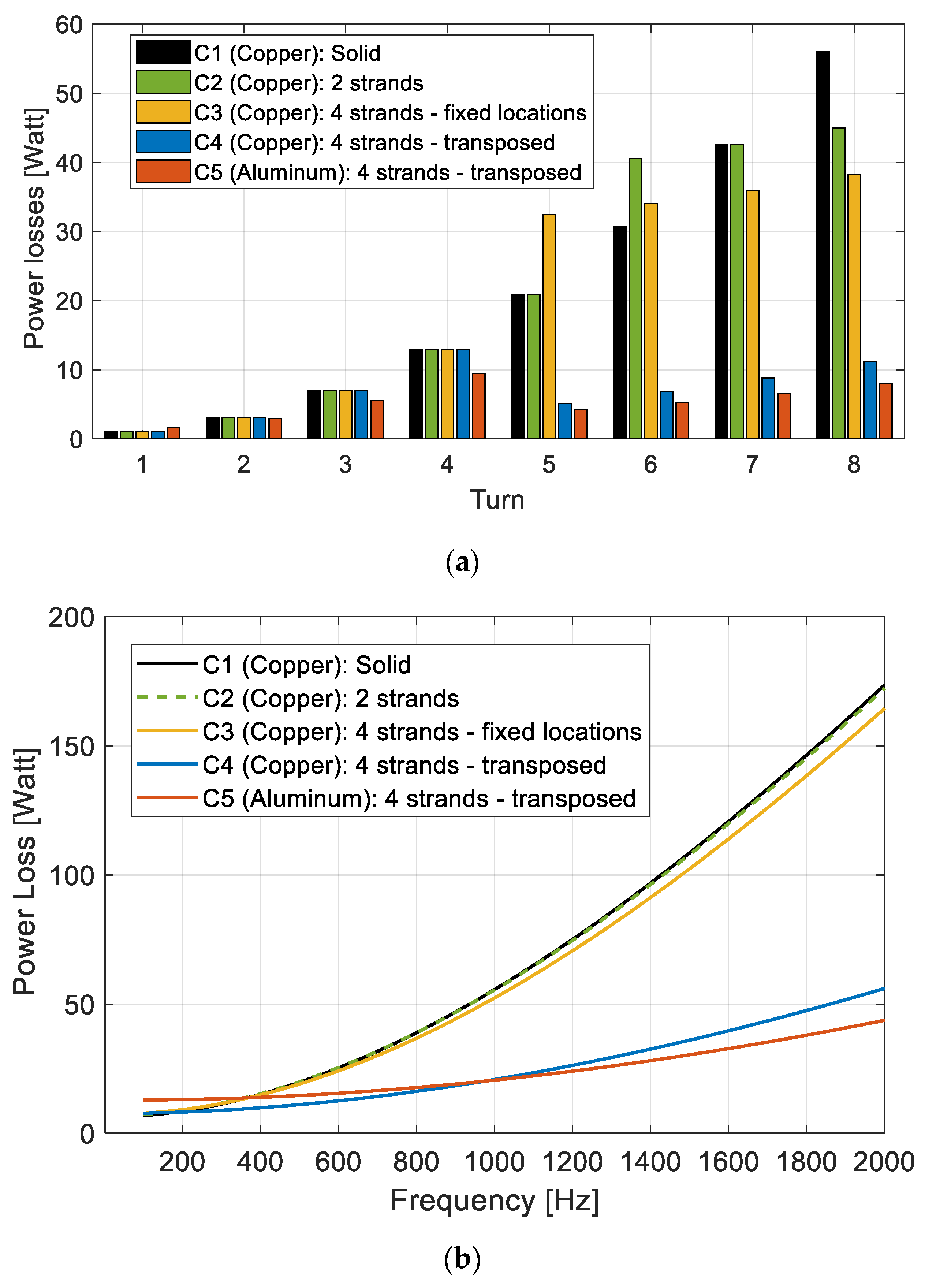
5.2. AC Loss Measurements

Both test samples are placed inside an E-shape core with the exact same design. The AC losses are then measured at different frequency levels (up to 2 kHz), using the test setup in Figure 12. A DC source is used for the DC losses measurements. Additionally, a 12 kVA amplifier is used as an AC variable voltage variable frequency input source for the AC loss measurements. Additionally, voltage and current probes are used to measure the voltage and the current of the test sample. Moreover, a dSpace MicroLabBox 1202 is used as a real time interface and for data acquisition (DAQ). There is also a power analyzer (PA4000) used to measure the AC and DC losses. A 4-channel scope is used to monitor the waveforms. The test sample is connected in series with a water-cooled power resistor. This zero-inductance resistance is useful to maintain sinusoidal current waveforms at high frequencies. Finally, a specially designed cooling jacket is also used with a water chiller to maintain the temperature at a constant level (see Appendix A). The main purpose of this devise is to perform the AC loss measurements at a defined temperature value.
The results are compared with those from the AM solid copper coil, as shown in Figure 13. As expected, the total AC losses of the semi stranded aluminum coil start to reduce significantly at frequencies above 300 Hz. Additionally, the total power losses are decomposed into three main components; core losses, DC losses, and AC losses.
The core loss in the E-shape core is calculated from its components; hysteresis loss, classical eddy current loss and excess loss, as indicated in the following equation:
P c o r e = K h   f   B m α + K c l f 2 B m 2 + K e x c f 1.5 B m 1.5
where Kh and α are the hysteresis coefficient and exponent. Kcl and Kexc are the classical eddy current loss and excess loss coefficients. All these coefficients are estimated from curve fitting of the measured iron losses of the laminated silicon steel at different magnetic flux densities (Bm) and frequencies (f). The core losses are equal for both coils. The main differences are in the DC and AC losses.
In the DC losses, it is clear that the copper coil has lower DC losses compared to the aluminum one. However, as the frequency increases, the AC losses of the copper coil starts to increase to extremely high levels. This is not the case for the semi stranded aluminum coil in which the AC losses increase slowly with the frequency. As a result, it has an overall better performance.
To sum up, it is clear that the semi stranded aluminum coil can effectively limit the AC loss component especially at high frequencies. That is the main reason behind its superiority over the 3D printed copper coil at high frequency domain with only 30% weight. Accordingly, these proposed coils have the potential for improving power density and efficiency in different weight sensitive applications, including electric traction, and automotive applications. Furthermore, additive manufacturing technology will certainly help in developing the process of electrical machines manufacturing especially with the emergence of new tools such as multi material printing which allows for simultaneous printing of conducting and non-conducting material. This will be very beneficial for the printing of electrical windings along with the electrical insulation.

6. Conclusions

This paper highlights the importance of additive manufacturing technology to print unconventional windings for high performance electrical machines. With unlimited design freedom, a novel concept is introduced for semi stranded windings with halls solid and half stranded turns. Additionally, this study is mainly aiming to overcome the undesirable AC conduction effects that occur during at high frequency in high speed electrical machines. Using a hybrid method of FEM and experimentation, the effect of strands transposition is investigated under controlled strand locations. Further, by balancing between the DC and AC winding losses, a novel semi-stranded coil is proposed combining high fill factor and transposed strand locations. This special design is prototyped using 3D printing technology using ultralight aluminum alloy. Additionally, the thermal performance of the proposed semi stranded coil is investigated at worst heat scenarios. In addition, the AC losses are measured and compared with the conventional design of a single-strand copper coil. It is verified that the proposed semi-stranded coil can provide much better electromagnetic performance as well as lower top temperature at high frequency domain with only 30% of the weight. The proposed coil is a very strong candidate for weight sensitive electrical machines with high power density requirements at high frequency domain.

Author Contributions

A.S., writing—original draft preparation; A.S., M.N.I. and P.S., review and editing. All authors have read and agreed to the published version of the manuscript.

Funding

This research is supported by the Research Foundation—Flanders (FWO) in the strategic based project (No: S001721N) entitled Multi-Material Additive Manufacturing for Electrical Machines with increased performance (AM4EM).

Conflicts of Interest

The authors declare no conflict of interest.

Appendix A

In order to perform the AC loss measurements at a defined temperature value, a specially designed cooling jacket is used with a water chiller to maintain the temperature at a constant level, as shown in Figure A1. Moreover, a weight comparison between the 3D printed copper and aluminum coils is shown in Figure A2. It is clear that the aluminum coil has saved more that 70% of the weight.
Figure A1. Assembly of a test sample with a cooling jacket for temperature control.
Applsci 13 01653 g0a1
Figure A2. Weight comparison between 3D printed copper and aluminum coils.
Applsci 13 01653 g0a2

References

  1. Standard, B. Mercedes-Benz EV Threatens Tesla with Record 1000 KM on Single Charge. Available online: https://www.business-standard.com/article/automobile/mercedes-benz-ev-threatens-tesla-with-record-1-000-km-on-single-charge-122041500616_1.html (accessed on 20 April 2022).
  2. Selema, A. Development of a Three-Phase Dual-Rotor Magnetless Flux Switching Generator for Low Power Wind Turbines. IEEE Trans. Energy Convers. 2020, 35, 828–836. [Google Scholar] [CrossRef]
  3. Selema, A.; Gulec, M.; Ibrahim, M.N.; Sprangers, R.; Sergeant, P. Selection of Magnet Wire Topologies with Reduced AC Losses for the Windings of Electric Drivetrains. IEEE Access 2022, 10, 121531–121546. [Google Scholar] [CrossRef]
  4. Zhao, W.; Wang, X.; Wu, S.; Cui, S.; Gerada, C.; Yan, H. Eddy Current Losses Analysis and Optimization Design of Litz-Wire Windings for Air-Core Compulsators. IEEE Trans. Plasma Sci. 2019, 47, 2532–2538. [Google Scholar] [CrossRef]
  5. Selema, A.; Ibrahim, M.N.; Sergeant, P. Metal Additive Manufacturing for Electrical Machines: Technology Review and Latest Advancements. Energies 2022, 15, 1076. [Google Scholar] [CrossRef]
  6. Selema, A.; Van Coppenolle, M.; Ibrahim, M.N.; Sergeant, P. Multi-physic design of ultra-efficient smart motor enabled by additive manufacturing. Zenodo 2022. [Google Scholar] [CrossRef]
  7. Selema, A.; Ibrahim, M.N.; Vansompel, H.; Sergeant, P. Development of Yokeless Axial Flux Machine Using 3D-Printed Shape-Profiled Core. In Proceedings of the 2022 IEEE International Conference on Electrical Machines (ICEM), Valencia, Spain, 5–8 September 2022. [Google Scholar]
  8. Selema, A.; Ibrahim, M.N.; Sergeant, P. Electrical Machines Winding Technology: Latest Advancements for Transportation Electrification. Machines 2022, 10, 563. [Google Scholar] [CrossRef]
  9. Selema, A.; Ibrahim, M.N.; Sergeant, P. Non-Destructive Electromagnetic Evaluation of Material Degradation Due to Steel Cutting in a Fully Stacked Electrical Machine. Energies 2022, 15, 7862. [Google Scholar] [CrossRef]
  10. Hong, H.-S.; Liu, H.-C.; Jeong, G.-C.; Lee, J. Design of high-end SynRM based on 3D printing technology. In Proceedings of the 2016 IEEE Conference on Electromagnetic Field Computation (CEFC), Miami, FL, USA, 13–16 November 2016; p. 1. [Google Scholar]
  11. Ranjan, R.; Tangudu, J. Thermal design of high power-density additively-manufactured induction motors. In Proceedings of the 2014 IEEE Energy Conversion Congress and Exposition (ECCE), Pittsburgh, PA, USA, 14–18 September 2014; pp. 1325–1331. [Google Scholar]
  12. Waterman, J.; Clucas, A.; Costa, T.B.; Zhang, Y.; Zhang, J. Numerical modeling of 3D printed electric machines. In Proceedings of the 2015 IEEE International Electric Machines & Drives Conference (IEMDC), Coeur d’Alene, ID, USA, 10–13 May 2015; pp. 1286–1291. [Google Scholar]
  13. Selema, A.; Beretta, M.; Van Coppenolle, M.; Tiismus, H.; Kallaste, A.; Ibrahim, M.; Rombouts, M.; Vleugels, J.; Kestens, L.; Sergeant, P. Evaluation of 3d-Printed Magnetic Materials for Additively-Manufactured Electrical Machines. J. Magn. Magn. Mater. 2023; in press. [Google Scholar] [CrossRef]
  14. An, B.W.; Kim, K.; Lee, H.; Kim, S.-Y.; Shim, Y.; Lee, D.-Y.; Song, J.Y.; Park, J.-U. High-Resolution Printing of 3D Structures Using an Electrohydrodynamic Inkjet with Multiple Functional Inks. Adv. Mater. 2015, 27, 4322–4328. [Google Scholar] [CrossRef] [PubMed]
  15. Vaithilingam, J.; Simonelli, M.; Saleh, E.; Senin, N.; Wildman, R.D.; Hague, R.J.M.; Leach, R.K.; Tuck, C.J. Combined Inkjet Printing and Infrared Sintering of Silver Nanoparticles using a Swathe-by-Swathe and Layer-by-Layer Approach for 3-Dimensional Structures. ACS Appl. Mater. Interfaces 2017, 9, 6560–6570. [Google Scholar] [CrossRef] [PubMed]
  16. Li, W.; Hu, D.; Li, L.; Li, C.-F.; Jiu, J.; Chen, C.; Ishina, T.; Sugahara, T.; Suganuma, K. Printable and Flexible Copper–Silver Alloy Electrodes with High Conductivity and Ultrahigh Oxidation Resistance. ACS Appl. Mater. Interfaces 2017, 9, 24711–24721. [Google Scholar] [CrossRef] [PubMed]
  17. Raab, S.J.; Guschlbauer, R.; Lodes, M.A.; Körner, C. Thermal and Electrical Conductivity of 99.9% Pure Copper Processed via Selective Electron Beam Melting. Adv. Eng. Mater. 2016, 18, 1661–1666. [Google Scholar] [CrossRef]
  18. Gradl, P.R.; Protz, C.; Greene, S.E.; Ellis, D.; Lerch, B.; Locci, I. Development and Hot-fire Testing of Additively Manufactured Copper Combustion Chambers for Liquid Rocket Engine Applications. In Proceedings of the 53rd AIAA/SAE/ASEE Joint Propulsion Conference, Atlanta, GA, USA, 10–12 July 2017; American Institute of Aeronautics and Astronautics: Reston, VA, USA, 2017. [Google Scholar]
  19. Louvis, E.; Fox, P.; Sutcliffe, C.J. Selective laser melting of aluminium components. J. Mater. Process. Technol. 2011, 211, 275–284. [Google Scholar] [CrossRef]
  20. Selema, A.; Ibrahim, M.N.; Sergeant, P. Mitigation of High-Frequency Eddy Current Losses in Hairpin Winding Machines. Machines 2022, 10, 328. [Google Scholar] [CrossRef]
  21. Fateri, M.; Gebhardt, A.; Hötter, J.-S.; Knothe, M.; Schmidt, F.; Rieper, H. Numerical and Experimental Investigation of Selective Laser Melting of Silver. In Proceedings of the Fraunhofer Direct Digital Manufacturing Conference (DDMC 2012), Berlin, Germany, 14–15 March 2012; Available online: https://www.researchgate.net/publication/264548342_Numerical_and_Experimental_Investigation_of_Selective_Laser_Melting_of_Silver (accessed on 2 January 2023).
  22. Singh, G.; Missiaen, J.-M.; Bouvard, D.; Chaix, J.-M. Copper extrusion 3D printing using metal injection moulding feedstock: Analysis of process parameters for green density and surface roughness optimization. Addit. Manuf. 2021, 38, 101778. [Google Scholar] [CrossRef]
  23. Rosochowski, A.; Presz, W.; Olejnik, L.; Richert, M. Micro-extrusion of ultra-fine grained aluminium. Int. J. Adv. Manuf. Technol. 2007, 33, 137–146. [Google Scholar] [CrossRef]
  24. Wu, F.; EL-Refaie, A.M.; Al-Qarni, A. Additively Manufactured Hollow Conductors for High Specific Power Electrical Machines: Aluminum vs Copper. In Proceedings of the 2021 IEEE Energy Conversion Congress and Exposition (ECCE), Vancouver, BC, Canada, 10–14 October 2021; pp. 4397–4404. [Google Scholar]
  25. Simpson, N.; North, D.J.; Collins, S.M.; Mellor, P.H. Additive Manufacturing of Shaped Profile Windings for Minimal AC Loss in Electrical Machines. IEEE Trans. Ind. Appl. 2020, 56, 2510–2519. [Google Scholar] [CrossRef] [Green Version]
  26. Selema, A.; Ibrahim, M.N.; Sergeant, P. Additively Manufactured Ultralight Shaped-Profile Windings for HF Electrical Machines and Weight-Sensitive Applications. IEEE Trans. Transp. Electrif. 2022, 8, 4313–4324. [Google Scholar] [CrossRef]
  27. Selema, A.; Ibrahim, M.N.; Sprangers, R.; Sergeant, P. Effect of Using Different Types of Magnet Wires on the AC Losses of Electrical Machine Windings. In Proceedings of the 2021 IEEE International Electric Machines & Drives Conference (IEMDC), Hartford, CT, USA, 17–20 May 2021; pp. 1–5. [Google Scholar]
  28. Nonneman, J.; Schoonjans, T.; T’Jollyn, I.; Selema, A.; Sprangers, R.; De Paepe, M. Thermal Property Determination of Different Electric Machine Wire Types by Model Variable Fitting on Measurements. In Proceedings of the 2022 IEEE International Conference on Electrical Machines (ICEM), Valencia, Spain, 5–8 September 2022; pp. 1383–1389. [Google Scholar]
  29. Zhao, Y.; Li, D.; Pei, T.; Qu, R. Overview of the rectangular wire windings AC electrical machine. CES Trans. Electr. Mach. Syst. 2019, 3, 160–169. [Google Scholar] [CrossRef]
Figure 1. Shape profiled 3D printed coil with uneven turns [26].
Applsci 13 01653 g001
Figure 2. Current density distribution at high frequency (2 kHz) in semi-stranded coils compared to the solid single-strand coil.
Applsci 13 01653 g002
Figure 3. Strands allocation in the fixed strand arrangement and the transposed one.
Applsci 13 01653 g003
Figure 4. Electrical circuit for the individual conductors in the semi-stranded coil.
Applsci 13 01653 g004
Figure 5. Comparison between the solid single-strand copper coil and the semi-stranded coils. (a) Total losses in each turn at high frequency of 2 kHz; (b) total losses in the entire coil at different frequency levels.
Applsci 13 01653 g005
Figure 6. Worldwide harmonized Light-duty vehicles Test Cycles (WLTC) for passenger vehicles with high power-to-weight ratio.
Applsci 13 01653 g006
Figure 7. Comparison between the maximum temperature under the same driving cycle (WLTC).
Applsci 13 01653 g007
Figure 8. Comparison between the thermal profile at the worst case scenario under the same cooling conditions.
Applsci 13 01653 g008
Figure 9. Reference coil case: 3D printed pure copper coil and assembly with a ferromagnetic core.
Applsci 13 01653 g009
Figure 10. A novel semi-stranded coil design with transposed strand locations.
Applsci 13 01653 g010
Figure 11. 3D printed semi-stranded coil with transposed strand location made using SLM of AlSi10Mg aluminum alloy.
Applsci 13 01653 g011
Figure 12. Test setup for the AC losses of the coil samples.
Applsci 13 01653 g012
Figure 13. The measured losses at different frequency levels for the solid copper coil and the semi-stranded aluminum coil.
Applsci 13 01653 g013
Disclaimer/Publisher’s Note: The statements, opinions and data contained in all publications are solely those of the individual author(s) and contributor(s) and not of MDPI and/or the editor(s). MDPI and/or the editor(s) disclaim responsibility for any injury to people or property resulting from any ideas, methods, instructions or products referred to in the content.

