Abstract
For the 3D self-assembly of microstructures, the net intrinsic stress within a hybrid metal layer stack is utilised to study the dynamics of the pairing of metallic MEMS shutter blades with dimensions of 150 × 400 µm2, representing a highly nonlinear Casimir system. The study focuses on two main geometries: (i) unpaired (freestanding) and (ii) paired metallic Micro-Electro-Mechanical Systems (MEMS) shutter blades. The hybrid metal stack comprises three metal layers that are under intrinsic stress, which enables the curling of the freestanding shutter blades. The top aluminum layer thickness is varied systematically, creating tailored stress in the shutter blades, resulting in the freestanding blades curling differently, as well as geometrical changes in the paired shutter blades. Concerning the thickness variations, a large technological processing window has been identified, during which the pairing of the neighbouring shutter blades occurs (the top aluminum layer thickness ranges between 70 and 88 nm). Circles and ellipses have been fitted to micrographs obtained by scanning electron microscopy (SEM) and Confocal Laser Scanning Microscopy (CLSM). We observed a trend of the reduction of the radius of curvature RoC (ranging between 17 and 79 µm) for the unpaired shutters, and eccentricity (0.36 < ε < 0.67) occurs throughout the system for the paired shutters. Concerning the specific shape of the overlapping region of the two blades of the paired shutters, three pairing scenarios (I, II, and III) have been identified, classified, evaluated, and reported. The overlapping length lo between the paired shutter blades ranges between 31 and 8 µm. These scenarios also reveal nonlinearities in the pairing process.
1. Introduction
Three-dimensional self-assembled forms induced by movements and deformations in the systems due to stress relaxation can be observed in nature and living organisms. Self-assembly in nature can occur in the DNA of some bacteria [1], the curling of blooming lilies [2], components of plant cell walls [3], and hydro-actuated ice plants [4]. Various new technologies can be developed when it becomes possible to establish a controlled and reproducible process that enables the fabrication of 3D self-assembled elements inspired by nature. The stress for such 3D elements can originate from lattice mismatch, grain boundaries, material thermal expansion, and thin film properties. Much research has been conducted, such as the fabrication of nanocomposite origami and kirigami structures [5,6]. The era of origami research opened a new door for 3D structuring and designs around 22 years ago [7,8]. Since then, several 3D self-assembled microstructures and innovations have been created using different materials, layer systems, sacrificial layers, and releasing methodologies for specific corresponding applications and purposes. The sacrificial layers can be organic or non-organic ones. In some techniques, no sacrificial layers are used. The layer system of the 3D origami structures can have diverse designs and comprising materials, which can provide unique optical and electrical properties, enabling a wide range of applications and breakthroughs [9]. For our structure and design, metallic MEMS shutter blades have been constructed in a 3D Yin-Yang shape called paired shutters.
Metallic MEMS shutters have been implemented for various applications, such as camera shutters [10], displays [11], smart glasses for daylight steering in buildings [12,13], and space instruments [14]. Our 3D MEMS shutter arrays are metal-based and non-planar ones. These micro-shutter elements are curled/rolled up in the initial state and can be electrostatically actuated to un-roll. MEMS microstructures elevated in a gaseous environment often experience intentional or unintentional adhesion to the base plates or substrates. This stiction can either occur during the removal of sacrificial layers to release the structures or during the actuation of the movable MEMS structures. When the restoring forces within the structures are not enough to overcome the interfacial forces such as capillary, Van der Waals, or Casimir ones, the shutter blades remain stuck. Usually, stiction is undesirable when it comes to MEMS devices and applications. Much research has been conducted to overcome such a dilemma [15]. Recently, our group demonstrated a novel method for the 3D self-assembly of paired neighbouring MEMS shutter blades [16] using mainly Casimir forces to keep the elements tightly attached.
The Casimir effect represents attraction or repulsion forces between two uncharged conducting plates at a very close distance depending on the materials of the plates, as well as the geometries. Figure 1 shows the case of attraction forces between two identical metal plates. In 1948, the Dutch physicist Hendrik Casimir [17] first proposed the existence of Casimir forces, and it has been proven step by step experimentally over time [18,19,20,21,22,23,24,25,26]. Still, it is a cutting-edge topic, and currently, many questions remain unanswered, motivating researchers to fill that research gap. In the last decade, the Casimir effect was explored from many different points of view, e.g., considering different materials, geometries, and methodologies [19,20].
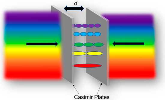
Figure 1.
Schematic of the attracting net force arising between two identical uncharged conducting plates.
Here, various geometries exploiting the Casimir force which have already been investigated in the existing literature are presented. We observed The molecular attraction force between a lens and a metal plate with a gap of between 10−5 and 10−4 cm was observed (Figure 2a) [21]. Crossed cylinders of mica (Figure 2b) at a thickness of 3 µm with a separation distance of 15 nm were used to detect and calculate the Casimir force. A further study shows the measurements of the Casimir forces between the two metal plates (Figure 2c) using a cantilever that freely oscillates at its clamping point and has the dimensions of 2 cm × 5 mm × 50:100 µm. The separation gap between the two metal plates varied from 2 to 12 µm considering that multiple material variances exist in that geometry, including various coatings on hybrid heterostructures. A further theory was published on the possibility of attractive or repulsive Casimir forces between two symmetrical bodies, such as hemispheres (Figure 2d). The theory states that when one is considering two identical dielectric objects, the Casimir force is attractive. Another investigation on repulsive and attractive Casimir forces demonstrated them as having a zipper-like geometry (Figure 2e). An article was published on the dependence of the Casimir force on the geometry, and the researchers considered two identical rectangular gratings of silicon with dimensions as follows: a thickness of 2.58 µm, a periodicity of 2 µm, a width of 908 nm. and a height of 1.5 µm, revealing a MEMS comb actuator geometry (Figure 2f) and a minimum separation distance between the gratings of 92 nm.
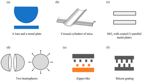
Figure 2.
Examples of different geometries demonstrating the existence of Casimir forces: (a) a lens and a metal plate [21], (b) two crossed cylinders of mica [27], (c) two metal plates [23] (d) two hemispheres [24], (e) a zipper-like geometry [25], and (f) a MEMS comb actuator via a silicon grating geometry [26]. All subfigures have been redrawn from the respective references.
The Casimir force shows a strong nonlinearity regarding the distance d between the two plates, which ranges between d−3 and d−4. In this paper, we use an effect called the “stiction dilemma” in the MEMS field, which refers to the undesired stiction of MEMS parts. The Casimir forces are used to self-assemble the shutter blades into arrays of paired ones to obtain a unique structure and further study the Casimir forces between the shutter blades. We define our structure as paired shutters that are in a Yin-Yang shape. The geometry was studied using the research in the fields of origami, 3D self-assembly, and Casimir forces. We measured the separation distance between the attached shutter blades to be 10 nm using SEM images, with a calculated threshold distance of 21 nm to keep the shutter blades tightly attached, according to our previous study [16], which is superior to other geometries. Yet, performing the measurements and calculation of the Casimir force remains challenging for us. This paper is part of a series of investigations on self-assembled structures, i.e., paired shutter blades. It focuses on identifying (i) the usable processing window when we are manipulating the stress within one metal layer via monitoring the changes in the whole comprising system and (ii) the possibilities of geometrical changes while we keep the shutter blades as a pair. In addition to self-assembly, in general, many applications could be achieved in the future: (a) Particle transport in magnetic stray field tubes [28] for drug delivery, lab on a chip systems, mass transport, and sensorics. The Yin-and-Yang shape is superior to the circular diameter used in [28], and it introduces additional attractive research fields using these new structures. (b) Shock absorbers for mobile systems. (c) Lightweight construction for material resource efficiency and weight reduction in construction is another possible application of macro- and micro-sized systems. Attractive applications could be enrolled in the field of the lightweight construction of microsystem technology and mobile systems (planes, cars, and drones, etc.). This paper is organised as follows: Section 2 describes the arrangement and the design of the unpaired, curled blades and the paired shutter blades. In Section 3, the key steps of the adapted fabrication process are repeated briefly, which are required for pairing the neighbouring shutter blades. Section 4 shows the experimental results, and it includes the analysis and discussion. It is divided into two subsections: (Section 4.1) with the freestanding unpaired shutter blades, and (Section 4.2), with the 3D self-assembled paired shutter blades. Finally, a summary and an outlook for future work are given in Section 5.
2. 3D MEMS Shutter Blades: Paired and Unpaired Geometries
The fabricated and studied shutter blades are rectangular in shape, with dimensions of 150 × 400 µm2, and they are fixed along one edge via a hinge structure to an anchor and arranged in 2D arrays. The shutter blades represent a multilayer hybrid metal stack consisting of aluminium (Al1), chromium (Cr), and aluminium (Al2). The individual thicknesses of the layer system are between 15 and 99 nm. Such a sandwich system possesses tailored intrinsic stress due to the involved Al and Cr thin film deposition characteristics. The tailored intrinsic stress produces the curling and freestanding features of the shutter blades. By finetuning the deposition parameters (i.e., the layer thicknesses), different curling geometries can be achieved (see Figure 3, left side (unpaired shutters)) and adapted to fit the targeted investigation goal. It has been noticed [16,29] that the fabricated curled shutter blades, which are initially in an open/curled state that is called ‘unpaired’, can self-assemble into paired shutters. The pairing occurs between two neighbouring shutters from two consecutive rows. Once the blades of two shutters are in contact, they are nearly inseparable. Figure 3 shows the different curling states of the unpaired shutters on the left hand side and the paired ones on the right hand side involving shutters A and B. The finally paired situation closely resembles a Casimir system of two uncharged metal plates that are brought together at a very close distance and experience strong attraction forces. Using theoretical model calculations [16], we could demonstrate that a separation of less than 21 nm is already enough to keep the two blades tightly attached only via Casimir forces. SEM micrographs of the trenches made by a focused Ga ion beam within the overlapping area of the paired shutter blades revealed an even smaller distance. This led to our strong belief in the key role of Casimir forces between the paired micro-shutter blades.
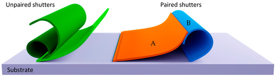
Figure 3.
Two fundamentally different geometries of the shutter blades: (left) unpaired with different optional curling states and (right) pairing of curled shutter blades A and B. The colour code used is explained in Section 4.
3. Fabrication Technology
The standard fabrication process for paired micro-shutters has been explained in detail previously [16], and our understanding is improved with further investigations on shutter pairing [29]. Here, a summary of the conducted steps in the process is provided: (a) the cleaning and preparing a glass substrate coated with a 650 nm thick layer of Fluorine-doped Tin Oxide (FTO), which serves as a bottom electrode, (b) the deposition of a 1000 nm thick isolation layer of silicon dioxide (SiO2) using the Plasma Enhanced Chemical Vapour Deposition (PECVD) technology, which serves as an isolation layer between the bottom and top electrodes, permitting the electrostatic actuation of the fabricated micro-shutters, (c) the optical lithography process is used to pattern the structure of the shutter blades, (d) the deposition of a three-layered metal stack using electron beam Physical Vapour Deposition (PVD), with thicknesses of dAl1 = 99 nm, dCr = 16 nm, and dAl2 = 88 nm, (e) the sacrificial layer of photoresist is dissolved in N-Methyl-2-Pyrrolidone (NMP), and (f) an we perform adapted drying process of the fabricated sample that promotes the shutter blades’ pairing. In the drying process that is depicted in Figure 4. (refer to Supplementary Materials Figure S2 for an image of the setup), the sample is immersed in isopropanol at a 25° tilt angle and covered with a steam bell, enabling the sample to dry in a gaseous environment. The drying setup is placed on a hotplate at 90 °C resulting in a 60 °C liquid bath. The liquid slowly evaporates and creates high vapour pressure inside the steam bell, pushing out the liquid of the steam bell into the outer tank, and later releasing it from the tank. A thin film of liquid is formed at the sample’s surface. Due to the gradual movement of the thin liquid film (row by row) and by means of the liquid surface tension, shutter A moves back, meanwhile, shutter B is still in a curling state. The combination of shutter B’s curling state and shutter A’s movement determines whether the shutter blades will pair or not. (Refer to the video in Supplementary Materials for a visual explanation.) This specific interplay of the two blades also determines which one of the observed three pairing scenarios occurs (for details, see the Section 4). We must bear in mind that the initial curling state is mainly affected by the multilayer metal stack comprising the shutter blades.
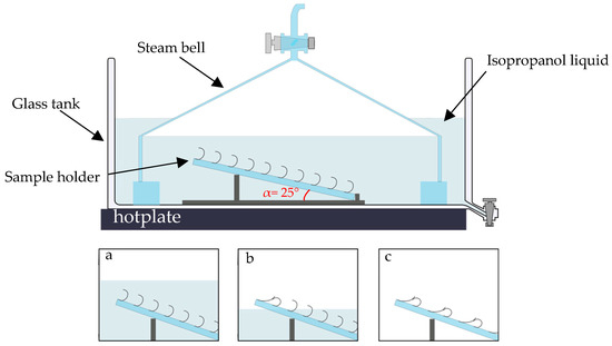
Figure 4.
The drying setup placed on a hotplate consisting of a glass tank with a dispenser and steam bell. The sample holder is placed inside, and this allows us to use differently angled positions. The gradual movement of the isopropanol liquid and forming of the paired shutters are shown in (a–c).
The pairing phenomenon was first observed in our study at dAl2 = 88 nm [16]. Among the others, the pairing the two blades is used to study the role of attractive Casimir forces. For the Casimir force, the interacting material is only Al. The change in the stressed metal layer thicknesses results in different RoCs. This can be observed via changing dAl2 or dCr or via changing both of them. To obtain clear results, the number of parameters changed was kept at a minimum. Therefore, only dAl2 was changed. The process was repeated to ensure its reproducibility and stability. The produced samples have revealed the uniformity of curling. Within this investigation, the thickness of dAl2 was varied, and we chose it to be 55, 66, 70, 75, 80, 84, 88, and 92 nm. We should bear in mind that the dimensions of one sample containing more than 150,000 identical single micro shutters are 10 × 10 cm2.
4. Experimental Results and Discussion
First, the fabricated samples were examined to identify whether the shutter blades show a pairing or not. Second, the geometrical changes in the shutter blades were studied and classified. SEM and CLSM were used to evaluate the physical geometry from the side (2D) using an appropriate magnification and resolution. The evaluation method is the following: the fabricated sample was manually cut into at least 16 sample pieces of a size of around 2.5 × 2.5 cm2 to enable the fitting of the sample pieces into the SEM chamber. High-resolution micrographs depicting the shutter blades’ cross-sections have been observed to allow us to perform an ideal evaluation. Once the micrographs were obtained, they were processed and analysed using ImageJ open software. Here, we classify the results and their corresponding discussion into two main categories regarding the two main structures observed: the freestanding unpaired shutters and the 3D self-assembled paired shutter blades (Yin-Yang shapes).
4.1. Freestanding Unpaired Shutter Blades
We expected to observe a circular geometry of the unpaired shutters due to the intrinsic stress within the metal stack layers. Hence, a circle was fitted to the curling geometries of various samples for analysing the shutter blades and measuring the radius of curvature (RoC). Figure 5a,b shows an example of the analysis that we conducted.
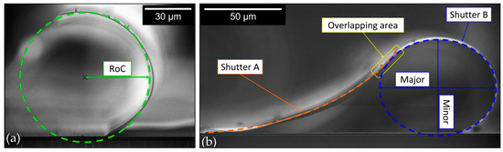
Figure 5.
Cross-section SEM micrographs of unpaired and paired micro-shutters with illustrations depciting the conducted analysis: (a) unpaired shutter blades with a fitted green circle to identify the radius of curvature (RoC), (b) the pairing and the overlapping area between the shutter blades, A and B, and the fitted orange and blue ellipses to idenfity both of the shutter blades. The extracted fit parameters are the major and minor axes.
From the plotted graph in Figure 6, a robust nonlinear trend of an increase in RoC of the shutters is observed with an increasing thickness of dAl2, i.e., with a higher dAl2, less curling of the shutters can be seen. The RoC starts at a value of around 17 µm for dAl2 = 55 nm, and it continuously increases to 79 µm for dAl2 = 92 nm. For each thickness dAl2, the evaluation of a set of side-view SEM and CLSM micrographs of at least 10 shutter blades provided us with data of sufficient statistical variance, finally leading to different error bar sizes. Note that for an increasing RoC, the uncertainty of the evaluation increases due to the fixed length of the micro shutters, hence, representing only the smaller sections of a full circle that must be fitted. As mentioned above, the hybrid metal stack of the shutter blade comprises three metal layers: Al, Cr, and Al. The deposited thin films of heavy metals (Cr) tend to reveal compressive stress, and light metals (Al) tend to be under tensile stress [30], resulting in the net intrinsic stress within the metal stack, and enabling the shutter blade to curl. With systematically changing dAl2 values, the shutter blades reveal a steady, but nonlinear, dependence of the parameters. In extreme cases, for dAl2 = 55 nm, the shutter blades close and form absolute circular tubes (see Figure 7). In opposite extreme cases, the blades flatten [12].
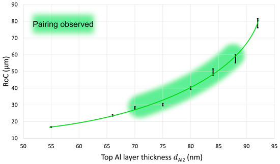
Figure 6.
The measured radius of curvature (RoC) of the curled shutter blades as a function of the thickness of the top Al layer (dAl2). The highlighted region refers to the thicknesses values that show pairings.
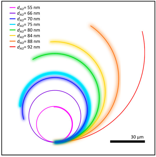
Figure 7.
Quantitative representation of the individual degree of curling as a function of different dAl2 values. The curling states with highlighted fading background are those ones revealing pairing in the subsequent figures.
An intuitive representation of the observed trend of decrease in the RoC is shown in Figure 7. Each of the displayed profiles has been constructed using the mean value of the statistically evaluated RoC of the shutter blades, revealing different curling states that correspond to the studied different thicknesses of dAl2.
4.2. 3D Self-Assembled Paired Shutter Blades (Yin-Yang shapes)
The 3D self-assembly pairing is a highly complex, nonlinear, and dynamic process. The process occurs between two neighbouring shutters (A and B) involving the respective blades. The shutter blades’ initial curling state and movement during the drying process determine the details of the pairing. Based on the evaluations of the experiments (paired and unpaired cases), a relatively large technological processing window for pairing (3D self-assembly of shutter blades) has been identified when the top Al layer thickness dAl2 ranges between 70 nm and 88 nm (see highlighted green region in Figure 6). Two significant results from the paired shutter analysis are observed: the geometrical changes in shutters A and B (forming a Yin-Yang shape) compared to the circular geometry of the unpaired shutters and the different pairing scenarios of the shutter blades. The RoCs of the unpaired shutters are identical. During the drying process, the shutters are deflected by surface tension forces, enabling the pairing, but these forces are not present after drying. Therefore, the RoCs of shutters A and B are not different before pairing (green curve in Figure 5a). After pairing, shutter A and shutter B form a Yin-Yang shape. Now, the curvatures of the two shutters, A and B, differ. The curvature contours of shutter A are shown in orange, and those of shutter B are shown in blue (Figure 5b). The geometry of the paired shutter blades (Yin-Yang shape) is expected to be more elliptical instead of circular compared to that of the unpaired shutters since both of the shutters pull at each other under the influence of Casimir forces as they are at a very close distance to one another. Therefore, the changes in the geometry have been evaluated by fitting ellipses to shutter B. Since shutter A is suffers from stiction to the substrate, deflecting its elliptical geometry, the evaluation focuses on shutter B. However, the stiction duration of shutter A to the substrate has been evaluated. The major axis is always oriented horizontally, i.e., parallel to the substrate, and the minor axis is perpendicular to it (Figure 5b). The eccentricity of shutter B is introduced to quantify the geometrical change and as a qualitative measure for the stiffness of the investigated paired shutters. Equation (1) [31] was used to calculate the eccentricity utilising the measured major axis 2p and the minor axis 2q of the fitted ellipses.
p and q are the major semiaxis and minor semiaxis, respectively. When p = q, then , and the ellipse becomes a circle (refer to text and Figure S3 in the Supplementary Material for a representation of the ellipse equation, the figure of a standard ellipse, the definition of all of the involved parameters, as well as serveral figures illustrating a selection of different cases of eccentricity). The results are plotted in Figure 8, showing the eccentricity as a function of dAl2.
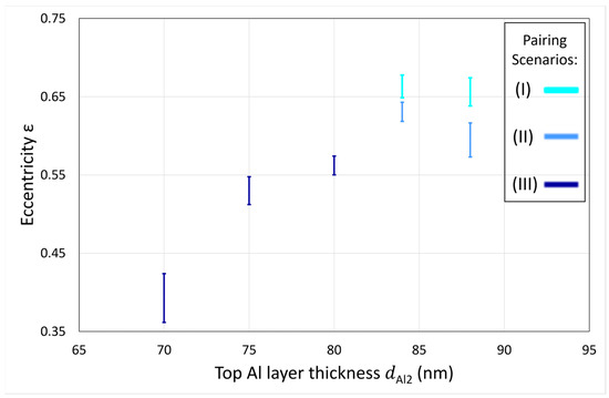
Figure 8.
The eccentricity of shutter B is shown as a function of the thickness of the top Al layer (dAl2).
The plot reveals that the smaller dAl2 is, the more circular shutter B’s geometry is, which also agrees with the results of the unpaired shutter blades, since increasing intrinsic stress (in the hybrid metal stack) results in a decreasing RoC, as well as qualitatively stiffer shutter blades. The error bars represent the conducted statistical variance in the investigated Yin-Yang geometries. Geometrical changes of the paired shutters are also observed in the overlapping area between the shutter blades, which we describe here as pairing scenarios. The plot shows that samples with dAl2 = 88 and 84 nm exhibit two pairing scenarios each. As dAl2 decreases, the pairing scenario changes for the samples with dAl2 = 80, 75, and 70 nm, therefore, a different pairing scenario is observed for each, respectively. The shape of the overlapping area defines the pairing scenario, i.e., how shutters A and B overlap and attach to each other, forming the Yin-Yang geometry. The three pairing scenarios are labelled with roman numbers (I), (II), and (III), and they are displayed in different blue tones in Figure 8 in relation to the eccentricity of shutter B. Scenario (I): shutter A is slightly curling at the top part of the pairing area (Figure 9 (I)). Scenario (II): both of the shutter blades are flat and completely attached inside the overlapping area (Figure 9 (II)). Scenario (III): shutter B curls at the lower part of the overlapping area, coming together with stronger curling on the entire lengths of shutter B (Figure 9 (IIIa)). Figure 9 (IIIb) reveals stronger curling on the entire lengths of shutter B.
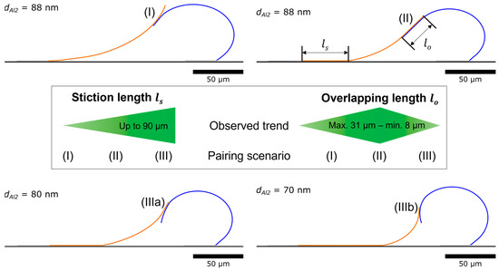
Figure 9.
Illustration of different pairing scenarios: (I) shutter A curls at the top part of the overlapping area, (II) shutter A and B are fully flat inside the overlapping area, (IIIa) shutter B curls at the lower part, and (IIIb) shutter B curls even more. In the centre of the figure is a representation of the measured overlapping length lo, ranging between a maximum of 31 µm (II) and a minimum of 8 µm (III), and the stiction length ls is observed to be 0 µm for scenario (I) increases up to 90 µm for scenario (III). The anchor of each shutter is shown in grey.
The different scenarios directly refer to the dynamics of the drying and 3D self-assembling of the shutter blades pairing process. Two videos (Video S1: Dynamics of the drying process) of the drying process for a sample with dAl2 = 84 nm have been recorded. The videos support that the initial curling state of the individual shutters strongly influences the chances of shutter A finding shutter B and pairing with it. As long as shutter A moves back via the liquid surface tension, the curling state of shutter B decides which pairing scenario will occur. Since drying is a sensitive process (involving gaseous and liquid turbulences), for the same thicknesses, different scenarios for dAl2 of 84 and 88 nm can occur due to the shape of shutter B during the moment of its attachment to shutter A (its RoC).
For us to conduct a further investigation of the observed paired scenarios, two measurements were considered. The overlapping length (l0) is defined as the length of the tight attachment between shutters A and B, and the stiction length (ls) is the length of shutter A that is sticking to the substrate (exclusive anchor length). See Figure 9 for an intuitive representation.
Starting from an average length of 16 µm for the overlapping in the pairing scenario (I), l0 increases in scenario (II), peaking at 31 µm (the most significant value observed in this investigation at dAl2 = 88 nm). Finally, it decreases again, reaching an observed minimum of 8 µm in scenario (III) at dAl2 = 70 nm. The resultant values are in accordance with the reported RoCs and eccentricities, since more pronounced curling reveals larger intrinsic stress, thereby it does not allow flattened overlapping to occur between the two shutters. Nevertheless, the point of the blades’ touch during the pairing process also affects the overlapping, as scenario (I) depicts. The stiction length of shutter A (ls) is continuously increasing, starting with no stiction (0 µm), which was observed for the paired shutters in scenario (I), and ending at up to 90 µm (III), meaning that 50 µm of shutter A is not sticking to the substrate in scenario (III). To expand, at low RoCs, more pronounced curling for shutters is observed. When shutter A is pulled towards shutter B by the liquid surface tension, shutter A finds shutter B after a longer time than that which is observed at high RoCs, and hence, sticking to the substrate with not enough restoring forces it to roll back up, which can be seen clearly in Figure 9 (scenarios IIIa and IIIb).
The results provide more insights into the geometry, its formation process, and how to introduce changes to obtain the desired geometries. However, we face various limitations, such as, the stiction of shutter A to the substrate and the turbulences of the isopropanol vapour during the drying process.
5. Summary and Outlook
An investigation has been performed on the geometrical changes in the freestanding and 3D self-assembled paired shutter blades due the influence of changing the thickness of the metal stack building system of the shutters. The investigation reveals the nonlinearity and dynamics of the process, as well as its complexity. For metallic MEMS shutter blades with dimensions of 150 × 400 µm2, the freestanding shutter blades have been analysed, and a technological processing window for 3D self-assembling pairing shutter blades was identified for the highest Al layer thickness dAl2 range of between 70 and 88 nm. The influence of the thickness changes has been observed in the geometrical shape changes for both the unpaired and paired shutter blades. The main results are presented in measurements of RoCs for the unpaired shutters, revealing a decreasing trend with a decaying dAl2 and a decreasing measure of eccentricity for the paired shutters, thereby showing the influence of pairing on the geometry of the shutters. The RoC of the unpaired shutters ranges between 17 and 79 µm, and the eccentricity of the paired shutters is between 0.35 and 0.67. The paired shutters have been categorised into three different pairing scenarios with respective overlapping lengths ranging between 8 µm and 31 µm. For 3D self-assembly with the tightest attachment due to a maximum overlapping area of the shutter blades, the following optimum parameters have been identified: the highest Al layer thickness of dAl2 of between 80 and 88 nm and an RoC of between 40 and 60 nm.
It has been noticed that once the shutter blades are paired, they can only be reopened with massive effort, e.g., an electrostatic actuation of >100 Volts [16]. Morevoer, ongoing studies with variable FIB trenches show that a threshold area is necessary to keep them attached using the Casimir force. Additionally, roughness studies in the overlapping region of the shutter blades are currently under work, and they will be published in a forthcoming publication. In terms of the future of that field, various applications can be considered: (a) Particle transport in magnetic stray field tubes [28,32] for mass transport and sensorics. The Yin and Yang shape is superior to the circular diameter used in [28], and it introduces additional attractive research fields. (b) Shock absorbers for mobile systems. (c) Lightweight construction for material resource efficiency and weight reduction in macro and micro fields. Other applications are, e.g., in the fields of buildings and mobile systems, such as planes, cars, and drones.
Supplementary Materials
The following supporting information can be downloaded at: https://www.mdpi.com/article/10.3390/app13031538/s1, Figure S1: SEM micrographs of fabricated micro-shutters with different thicknesses of the top Al layer dAl2: (a) Sample with dAl2 = 92 nm, unpaired and curled with high radius of curvature, (b) Sample with dAl2 = 55 nm, the shutter blade is rolled on itself, forming a tube, (c) Sample with dAl2 = 80 nm, showing an unpaired microshutter and the third pairing scenario between two shutter blades, (d) Sample with dAl2 = 70 nm, showing also the third pairing scenario and unpaired shutter blades behind, (e) Sample with dAl2 = 88 nm, showing the first and second pairing scenario for neighbouring shutter blade rows, and (f) Sample with dAl2 = 88 nm, showing an overview of homogeneous rows of 3D self-assembled paired shutters with the second pairing scenario; Figure S2: Image of the drying setup in real-time scale; side and top views; Figure S3: Represents a standard ellipse and the eccentricity, , for a selection of different cases. For a circle is resulting. Suppose increases and approaches 1; the geometry becomes more and more a flat ellipse. If q becomes larger than p, then the eccentricity and the ellipse are imaginary. This case is not relevant here; Figure S4: Schematic of the different eccentricities of the different pairing scenarios with their respective dAl2 for an intuitive representation of the observed trend for eccentricity; Video S1: Dynamics of the drying process.
Author Contributions
Conceptualisation, H.H., P.K., E.K. and B.E.; Methodology, B.E., P.K., E.K., R.D. and H.H.; Validation, B.E., P.K. and E.K.; Formal Analysis, E.K., P.K., B.E. and H.H.; Investigation, B.E. and R.D.; Writing—Original Draft Preparation, B.E.; Writing—Review and Editing, all authors; Visualization, B.E., E.K., P.K. and H.H.; Funding Acquisition, H.H. and E.K. All authors have read and agreed to the published version of the manuscript.
Funding
This research received financial support from DFG (Nos Hi 763/21-1 and Hi 763/19-1), BMBF (Nos. 13N14517 and 13N15740), and DBU (Nos. AZ23717, AZ20012/189, and AZ35501).
Institutional Review Board Statement
Not applicable.
Informed Consent Statement
Not applicable.
Data Availability Statement
Not applicable.
Acknowledgments
The authors would like to thank S. Akhundzada, B. Al-Qargholi, S. Buhmann, J. Fiedler, X. Yang, M. S. Q. Iskhandar, B. Kaban, N. Windus, K. Hasan, D. Löber, S. Nazemroaya, S. Liebermann, S. Baby, M. Qasim, M. Smolarczyk, S. Liu G. Nagajyothi, K. Darwish, G. Xu, A. Friedrichsen, J. Krumpholz, H. Wilke, N. Körte, A. Ehresmann, and T. Thomas for fruitful discussions and technological support.
Conflicts of Interest
The authors declare no conflict of interest.
References
- Horiuchi, H.; Takagi, M.; Yano, K. Relaxation of supercoiled plasmid DNA by oxidative stresses in Escherichia coli. J. Bacteriol. 1984, 160, 1017–1021. [Google Scholar] [CrossRef] [PubMed]
- Liang, H.; Mahadevana, L. Growth, geometry, and mechanics of a blooming lily. Proc. Natl. Acad. Sci. USA 2011, 108, 5516–5521. [Google Scholar] [CrossRef] [PubMed]
- Murugesan, Y.K.; Pasini, D.; Rey, A.D. Self-assembly mechanisms in plant cell wall components. J. Renew. Mater. 2015, 3, 56–72. [Google Scholar] [CrossRef]
- Harrington, M.J.; Razghandi, K.; Ditsch, F.; Guiducci, L.; Rueggeberg, M.; Dunlop, J.W.C.; Fratzl, P.; Neinhuis, C.; Burgert, I. Origami-like unfolding of hydro-actuated ice plant seed capsules. Nat. Commun. 2011, 2, 337. [Google Scholar] [CrossRef]
- Xu, L.; Shyu, T.C.; Kotov, N.A. Origami and Kirigami Nanocomposites. ACS Nano 2017, 11, 7587–7599. [Google Scholar] [CrossRef] [PubMed]
- Chalapat, K.; Chekurov, N.; Jiang, H.; Li, J.; Parviz, B.; Paraoanu, G.S.; Chalapat, K.; Li, J.; Chekurov, N.; Jiang, H.; et al. Self-Organized Origami Structures via Ion-Induced Plastic Strain. Adv. Mater. 2013, 25, 91–95. [Google Scholar] [CrossRef]
- Prinz, V.Y.; Seleznev, V.A.; Gutakovsky, A.K.; Chehovskiy, A.V.; Preobrazhenskii, V.V.; Putyato, M.A.; Gavrilova, T.A. Free-standing and overgrown InGaAs/GaAs nanotubes, nanohelices and their arrays. Phys. E Low-Dimens. Syst. Nanostruct. 2000, 6, 828–831. [Google Scholar] [CrossRef]
- Schmidt, O.G.; Eberl, K. Thin solid films roll up into nanotubes. Nature 2001, 410, 168. [Google Scholar] [CrossRef]
- Xu, B.; Lin, X.; Mei, Y. Versatile Rolling Origami to Fabricate Functional and Smart Materials. Cell Rep. Phys. Sci. 2020, 1, 100244. [Google Scholar] [CrossRef]
- Kim, C.H.; Hong, S. Study on the reliability of the mechanical shutter utilizing roll actuators. In Proceedings of the 2011 IEEE 24th International Conference on Micro Electro Mechanical Systems, Cancun, Mexico, 23–27 January 2011; pp. 501–504. [Google Scholar] [CrossRef]
- Pizzi, M.; Koniachkine, V.; Nieri, M.; Sinesi, S.; Perlo, P. Electrostatically driven film light modulators for display applications. Microsyst. Technol. 2003, 10, 17–21. [Google Scholar] [CrossRef]
- Hillmer, H.H.; Iskhandar, M.S.Q.; Hasan, M.K.; Akhundzada, S.; Al-Qargholi, B.; Tatzel, A. MOEMS micromirror arrays in smart windows for daylight steering. J. Opt. Microsyst. 2021, 1, 014502. [Google Scholar] [CrossRef]
- Lamontagne, B.; Fong, N.R.; Song, I.-H.; Ma, P.; Barrios, P.J.; Poitras, D. Review of microshutters for switchable glass. J. Micro/Nanolithography MEMS MOEMS 2019, 18, 040901. [Google Scholar] [CrossRef]
- Ilias, S.; Picard, F.; Larouche, C.; Kruzelecky, R.; Jamroz, W.; Le Noc, L.; Topart, P. Programmable optical microshutter arrays for large aspect ratio microslits. In Proceedings of the Photonics North 2008, Montréal, QC, Canada, 2–4 June 2008; Volume 7099, p. 70992D. [Google Scholar] [CrossRef]
- Petruzzella, M.; Zobenica, Ž.; Cotrufo, M.; Zardetto, V.; Mameli, A.; Pagliano, F.; Koelling, S.; van Otten, F.W.M.; Roozeboom, F.; Kessels, W.M.M.; et al. Anti-stiction coating for mechanically tunable photonic crystal devices. Opt. Express 2018, 26, 3882. [Google Scholar] [CrossRef] [PubMed]
- Akhundzada, S.; Yang, X.; Fiedler, J.; Käkel, E.; Al-Qargholi, B.; Buhmann, S.; Ehresmann, A.; Hillmer, H. A novel approach to construct self-assembled 3D MEMS arrays. Microsyst. Technol. 2022, 28, 2139–2148. [Google Scholar] [CrossRef]
- Casimir, H.B.G. On the attraction between two perfectly conducting plates. Proc. K. Ned. Akad. 1948, 360, 793–795. [Google Scholar]
- Lamoreaux, S.K. Demonstration of the casimir force in the 0.6 to 6μm range. Phys. Rev. Lett. 1997, 78, 5–8. [Google Scholar] [CrossRef]
- Munday, J.N.; Capasso, F. Precision measurement of the Casimir-Lifshitz force in a fluid. Phys. Rev. A At. Mol. Opt. Phys. 2007, 75, 060102. [Google Scholar] [CrossRef]
- Capasso, F.; Munday, J.N.; Iannuzzi, D.; Chan, H.B. Casimir forces and quantum electrodynamical torques: Physics and nanomechanics. IEEE J. Sel. Top. Quantum Electron. 2007, 13, 400–414. [Google Scholar] [CrossRef]
- Derjaguin, B.V.; Abrikosova, I.I.; Lifshitz, E.M. Direct Measurement of Molecular Attraction between Solids Separated by a Narrow Gap. Q. Rev. Chem. Soc. 1956, 10, 295–329. [Google Scholar] [CrossRef]
- Bressi, G.; Carugno, G.; Galvani, A.; Onofrio, R.; Ruoso, G.; Veronese, F. Experimental studies of macroscopic forces in the micrometre range. Class. Quantum Gravity 2001, 18, 3943–3961. [Google Scholar] [CrossRef]
- Bressi, G.; Carugno, G.; Onofrio, R.; Ruoso, G.; Onofrio, R.; Ruoso, G. Measurement of the Casimir Force between Parallel Metallic Surfaces. Phys. Rev. Lett. 2002, 88, 4. [Google Scholar] [CrossRef] [PubMed]
- Kenneth, O.; Klich, I. Opposites attract: A theorem about the Casimir force. Phys. Rev. Lett. 2006, 97, 160401. [Google Scholar] [CrossRef] [PubMed]
- Rodriguez, A.W.; Joannopoulos, J.D.; Johnson, S.G. Repulsive and attractive Casimir forces in a glide-symmetric geometry. Phys. Rev. A At. Mol. Opt. Phys. 2008, 77, 062107. [Google Scholar] [CrossRef]
- Wang, M.; Tang, L.; Ng, C.Y.; Messina, R.; Guizal, B.; Crosse, J.A.; Antezza, M.; Chan, C.T.; Chan, H.B. Strong geometry dependence of the Casimir force between interpenetrated rectangular gratings. Nat. Commun. 2021, 12, 600. [Google Scholar] [CrossRef] [PubMed]
- Tabor, D.; Winterton, R.H.S. Erratum: Surface forces: Direct measurement of normal and retarded van der Waals forces ( Nature (1968) 219 (1120)). Nature 1968, 220, 940. [Google Scholar] [CrossRef]
- Ueltzhöffer, T.; Streubel, R.; Koch, I.; Holzinger, D.; Makarov, D.; Schmidt, O.G.; Ehresmann, A. Magnetically Patterned Rolled-Up Exchange Bias Tubes: A Paternoster for Superparamagnetic Beads. ACS Nano 2016, 10, 8491–8498. [Google Scholar] [CrossRef]
- Kästner, P.; Käkel, E.; Akhundzada, S.; Donatiello, R.; Hillmer, H. Development of self-assembled 3D MEMS Paired Shutter Arrays for studies on Casimir forces. In Proceedings of the Technical Digest MOC, Jena, Germany, 25–28 September 2022; Volime 1054, pp. 74–75. [Google Scholar]
- Becker, F.G.; Cleary, M.; Team, R.M.; Holtermann, H.; The, D.; Agenda, N.; Science, P.; Sk, S.K.; Hinnebusch, R.; Hinnebusch, A.R.; et al. Handbook of Silicon Based MEMS Materials and Technologies, 2nd ed.; Matthew Deans: Fayetteville, NC, USA, 2015; Volume 7, ISBN 9772081415. [Google Scholar]
- Thomas, G.B.; Finney, R.L. Calculus and Analytic Geometry, 9th ed.; Addsion Welsey: Boston, CA, USA, 1996; ISBN 0201531747. [Google Scholar]
- Mei, Y.; Huang, G.; Solovev, A.A.; Ureña, E.B.; Mönch, I.; Ding, F.; Reindl, T.; Fu, R.K.Y.; Chu, P.K.; Schmidt, O.G. Versatile Approach for Integrative and Functionalized Tubes by Strain Engineering of Nanomembranes on Polymers. Adv. Mater. 2008, 20, 4085–4090. [Google Scholar] [CrossRef]
Disclaimer/Publisher’s Note: The statements, opinions and data contained in all publications are solely those of the individual author(s) and contributor(s) and not of MDPI and/or the editor(s). MDPI and/or the editor(s) disclaim responsibility for any injury to people or property resulting from any ideas, methods, instructions or products referred to in the content. |
© 2023 by the authors. Licensee MDPI, Basel, Switzerland. This article is an open access article distributed under the terms and conditions of the Creative Commons Attribution (CC BY) license (https://creativecommons.org/licenses/by/4.0/).