Abstract
Geotextile is one of the reinforcement materials adopted in many engineering structures. Conventional geotextiles have a limited reinforcement effect due to the insufficient friction strength between geotextiles and soils. This paper proposes a novel type of geotextile with stitched transverse ribs to improve the reinforcement effect. A series of large-scale direct shear tests have been conducted, and the improvement characteristics between conventional geotextiles, geogrids, and the novel geotextiles have been studied. The results show that the novel stitched transverse rib geotextiles can significantly increase the shear strength compared to conventional geotextiles and geogrids. Moreover, due to the restraint and friction effect of ribs on the soils, the reinforcement effect of the novel geotextile is increased with increasing ribs. Insights from this study can provide a new understanding of the novel stitched transverse ribs geotextile’s reinforcement mechanism in engineering.
1. Introduction
Because of being lightweight, having high strength, high flexibility, corrosion resistance, ease of storage, transportation, and construction [1], and due to their cost-effectiveness and environmental friendliness [2], geotextiles have been widely used in road, railway [3], airport, port [4], and other major engineering construction fields since the end of the last century. Geotextiles can play the role of isolation, filtration, reinforcement, etc. In reinforced soil engineering, as one of the early and widely used reinforcement materials, the application of a geotextile can reduce displacements and stress values, and increase the bearing capacity [5,6]. However, the reinforcement effect of conventional geotextiles is limited in practice since a geotextile is distributed in a two-dimensional plane and the interface friction between geotextile and soil is not enough [6,7,8]. Because of the deficiency of geotextiles, geogrids have more applications in engineering, and some scholars have studied geogrid reinforcement [9,10]. Although geogrids can provide a better interlocking effect on soils, the tensile strength of geogrids is still less than that of geotextiles, as the tensile strength of geotextiles can achieve 1000 kN/m, indicating that geotextiles should provide a very good reinforcement effect. Therefore, a new reinforcement form thus needs to be developed to take full advantage of the tensile strength of geotextiles [11].
The passive resistance of the transverse ribs, the frictional resistance of the longitudinal ribs, and the embedded locking and occlusion of the mesh all contribute to the reinforcement effect between geosynthetics and soils. Among them, 60~70% of the resistance comes from the transverse ribs [11,12,13]. On the basis of existing research results, a novel type of geotextile with stitched transverse ribs is proposed to improve the reinforcement effect between geotextile and soil. The reinforcement effect is determined by the friction characteristics between geotextile and soil, influenced by many properties, such as the types of geotextiles and filled soils, the compaction quality of soils, the test boundary conditions, and so on [14,15,16]. It is important to obtain an accurate reinforcement effect of geotextiles by carrying out tests [17]. A series of large-scale direct shear tests have investigated the improvement characteristics between conventional geotextiles, geogrids, and the novel geotextile. The reinforcement mechanism of the novel stitched transverse ribs geotextile is also studied. Insights from this study can provide a new understanding of the novel stitched transverse ribs geotextile’s reinforcement mechanism in engineering.
2. Direct Shear Tests
2.1. Test Materials
In this paper, sand was used as the test filler, and four different types of conventional geotextiles and one uniaxial geogrid were selected as the reinforcement materials, as shown in Figure 1. The width and length of the samples were determined by the size and fixing method of the shear box. In order to ensure the fixation of the samples, the length of the cut sample was 400 mm longer than the length of the shear box. The material properties were tested according to the “JTG ESO-2006 Test Methods of Geosynthetics for Highway Engineering”. The material properties of the sand are shown in Table 1, and the parameters of the conventional geosynthetics are shown in Table 2.
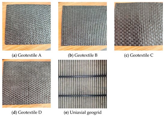
Figure 1.
Comparison of geosynthetics.

Table 1.
Material properties of sand.
Table 2.
Material properties of conventional geosynthetics.
The novel stitched transverse ribs geotextile is shown in Figure 2. A 1000 mm × 1500 mm geotextile was set as the bottom layer of reinforcement, then 400 mm × 1000 mm ribs were cut out and sewn to the bottom layer of the geotextile at equal intervals of 300 mm. This allowed them to play a similar role as the geogrid horizontal ribs in three dimensions. This enhanced the friction between the ribs and the filler and limited the displacement of the filler. The schematic diagram of the reinforcement is shown in Figure 3.
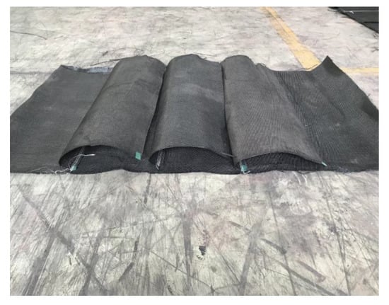
Figure 2.
Novel stitched transverse ribs geotextile.
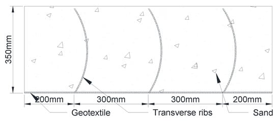
Figure 3.
Schematic diagram of reinforcement.
2.2. Test Equipment
The large drawing and straight shearing instrument used in this test was able to carry out the straight shearing test and pulling test of geosynthetics and soil, as shown in Figure 4. The upper box was pulled through the jack on both sides to achieve the shearing of geosynthetic materials and soil, and the normal load was applied by the reaction force of air pressure on the top steel plate. The horizontal displacement was measured by the displacement sensor, and the shear force was measured by the force sensor. The shear force and the relative displacement on the shear surface were recorded by the computer automatically.
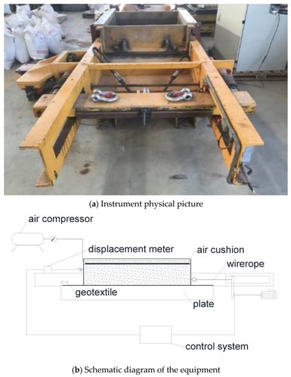
Figure 4.
The large drawing and straight shearing instrument.
The length and width of the removable upper box were 1000 mm and 1000 mm, the length and width of the fixed lower box were 1200 mm and 1000 mm, therefore the boundary effect of the shear box was eliminated and a larger shear displacement could be produced. There was a 10 mm high gap between the upper and lower shear boxes to eliminate the friction between the upper and lower boxes themselves during the shearing process. To ensure that the shear surface remained unchanged during the shear process, a steel plate was placed in the lower box instead of deformable filler, which should have little effect on the interface characteristics of geotextiles and soil since the reinforcement material used in the test is geotextile which can play a good isolation effect on the upper and lower layers of materials. Moreover, the steel plate lower layer can simulate rigid boundary conditions such as the junction of old and new roadbeds.
2.3. Test Method
Nine tests were carried out to study the influence of geosynthetics on reinforcement characteristics. The tests were conducted following the “JTGE50-2006 Test Methods of Geosynthetics for Highway Engineering”. To compare the interfacial shear properties of sand itself, sand with geotextile, sand with geogrid, and sand with stitched transverse ribs geotextile, shear tests under different vertical stresses (25, 50, 100, and 150 kPa) on pure sand, four conventional geotextiles, and a uniaxial geogrid reinforced soil were conducted. The same tests were then conducted on the geotextile B with stitched transverse ribs, with better performance. The test conditions are shown in Table 3.
Table 3.
Basic physical parameters of geosynthetics.
3. Experimental Results
3.1. Comparison of Reinforcement Effect of Different Reinforcement Materials
The relationship curves between shear stress and displacement of the four geotextiles and geogrids obtained in the tests are shown in Figure 5. It can be seen that the shear stress increases with the increase of shear displacement at the beginning of the test. Generally, the shear stress reaches the maximum value when the shear displacement reaches 5~15 mm. The maximum stress value increases with the increase of vertical stress. The curve is flatter, and the peak point appears earlier when the normal stress is small. The position of the peak point is delayed when the normal stress increases. Under normal stress of 150 kPa, the peak shear stress of woven geotextiles A and B is about 20% higher than that of unreinforced geotextiles, and the uniaxial geogrid improved 28% in shear strength.
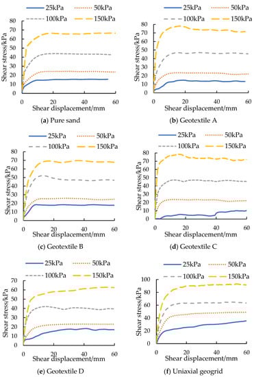
Figure 5.
Shear stress–displacement curves for different geosynthetics.
The relationship between the maximum shear stress and normal stress obtained from each test is shown in Figure 6. It can be seen that there is an excellent linear relationship between the maximum shear stress and the normal stress, and all of them are in accordance with the Mohr–Coulomb strength criterion. According to Figure 6, the cohesion and friction angle between the interface of the reinforced soil under different reinforcing materials can be obtained, as shown in Table 4.
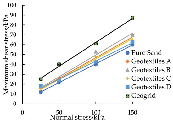
Figure 6.
Curves of maximum shear stress and normal stress.
Table 4.
Interface strength under different working conditions.
It can be seen from Table 4 that the cohesion and friction angle of reinforcement materials except Geotextile D increased compared with those of pure sand; the cohesion and friction angle of the geogrid reinforced structure interface is the largest. Among the four kinds of geotextiles, B has the best reinforcement effect, compared with geotextiles C and D. Its surface is rough enough to provide greater friction, forming an interlocking effect with sand. Compared with the woven geotextile A, B is thicker and more robust. Therefore, geotextile B was selected for subsequent tests.
3.2. Comparison of Shear Strength of Stitched Rib Geotextile Reinforcement
The relationship curves between shear stress and displacement of geotextile B stitched one, two, and three transverse ribs are shown in Figure 7. It can be seen that the shear stress increases with the increase of the shear displacement during the test. The positions of the peak points under three working conditions are different; the displacement corresponding to the peak shear stress point is about 60 mm, 50 mm, and 40 mm, when one, two, and three transverse ribs are stitched, respectively. This is mainly because the distance between the transverse ribs will decrease with the number of transverse ribs, resulting in stronger constraints from the soil and faster-achieved peak strength in the shear process. It can be summarized as follows: as the number of transverse ribs increases, the displacement peak value increases gradually, and the peak position advances gradually, which indicates that the structure has a strong ability to limit deformation. In practical application, it can exert its strength earlier, limit the deformation of the reinforced structure, and thus ensure the safety of the overall structure.
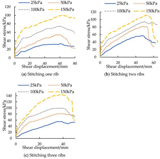
Figure 7.
Shear stress–displacement curves of sutured ribbed geotextiles with reinforcement.
Figure 8 shows the picture of the geotextile after damage. It can be seen that the damage occurs mainly at the stitching between the transverse ribs and the bottom geotextile, while a slight tear also appears at the edge of the bottom geotextile. According to the damage degree of the geotextile stitched with three transverse ribs, the damage is most serious at the first transverse rib joint, which is torn almost completely; a slight tear occurs at the second transverse rib joint, while the third transverse rib is intact with no breakage. It can be concluded that the order of the reinforcement effect on the three layers of transverse ribs in the test is: the first layer > the second layer > the third layer, where the first layer is closest to the outer edge, and the second and third layers are more inward sequentially. With the movement of the shear box, the soil on the left side of the transverse rib is squeezed first, so the friction force and the resistance of the transverse rib on the left side of the geotextile are exerted, and the shear force on the right side is weak. With the increase of the shear displacement, the strength on the left side of the reinforcement soil interface and the strength of the transverse rib gradually reach the limit value. Then, the right side of the reinforcement begins to bear more loads, and the shear force gradually shifts to the right side. It can be seen from the shear stress displacement curves of the tiled reinforcement and the stitched rib reinforcement that the shear displacement reaches the stable maximum value before 15 mm when the reinforcement is tiled. The shear displacement of the stitched transverse ribs reinforcement comes to 40~60 mm at the peak value of the shear stress, which is the value required for tensile failure at the fabric joint. At this time, the failure of the main stressed transverse rib (that is, the first transverse rib) reduces the overall shear stress.
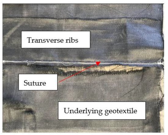
Figure 8.
Geotextile B after destruction.
The shear stress at the shear displacement of 10 mm under various working conditions is shown in Figure 9. It can be seen that the order of the shear stress value is: geotextile stitched with three ribs > geogrid > geotextile stitched with two ribs > geotextile stitched with one rib > flattening geotextile. When the shear displacement is small, the effect of the geotextile stitched with one or two transverse ribs is not obvious compared with that of the tiled reinforcement. The reason is the friction provided by the underlying geotextile increases rapidly, but the transverse ribs need more displacement to play their role. We can see that the reinforcement effect of the bottom geotextile is mainly produced by the friction between the bottom geotextile and the particles. In contrast, that of the geotextile with one stitched transverse rib is not only reflected in the friction with soil particles but also the extrusion on the transverse rib. The geotextile stitched with three transverse ribs has the best reinforcement effect and the most obvious increase in shear stress. The shear stress under four normal loads is greater than the geogrid. It can be seen that the geotextile stitched with three transverse ribs can provide greater shear resistance when the deformation is small.
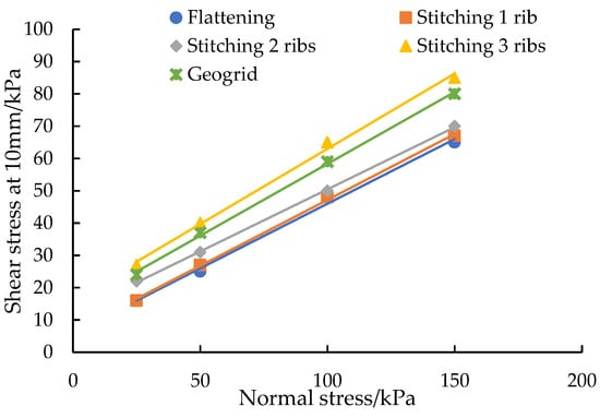
Figure 9.
Comparison of shear stress of different stiffened structures at 10 mm.
The relationship between the maximum shear stress and normal stress obtained from each test is shown in Figure 10. It shows that the shear strength of the structure can be significantly improved by sewing ribs. Under low normal stress (25 kPa), the maximum shear stress of the geotextile structure stitched with one, two, and three transverse ribs are 40 kPa, 55 kPa, and 62 kPa, respectively. Under high normal stress (150 kPa), the maximum shear stress of the geotextile structure stitched with one, two, and three transverse ribs are 100 kPa, 114 kPa, and 140 kPa, respectively. There is a good linear relationship between the maximum shear and the normal stress, and the pseudo-cohesion and friction angle are improved compared with the geogrid. The shear strength of one transverse rib is close to that of the geogrid, and the improved effect is mainly reflected in the pseudo-cohesion, and the improvement of the friction angle of three ribs is more obvious. According to the results shown in Figure 7, Figure 9 and Figure 10, the increase in the number of stitched transverse ribs can greatly improve the shear strength and enhance the constraint effect on the filler, making the structure exert a shear effect earlier. As the filler used in these tests is sand with small particle sizes, the thickness of the influence zone of the geogrid is small. The reinforcement mechanism is changed, and the influence range of the reinforcement is expanded by using the geotextile sewn with ribs, so the strength of the structure is greatly improved.
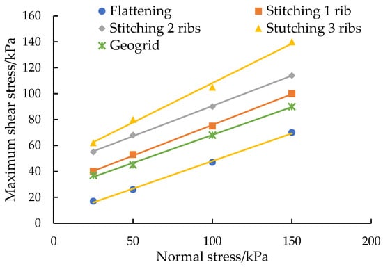
Figure 10.
Relationship between maximum shear stress and normal stress.
3.3. Reinforcement Mechanism of the Novel Geotextile with Stitched Transverse Ribs
The reinforcement effect between geosynthetics and soils contains passive resistance of transverse ribs, frictional resistance of longitudinal rib, and the embedded locking and occlusion of mesh.
Geotextiles stitched with transverse ribs can not only restrict the lateral displacement of the fill but also contribute greatly to the whole shear strength due to the friction between sand particles on both sides of the ribs and the geotextile. The shear strength of the geotextile with stitched ribs is mainly composed of three parts, as shown in formula (1) and Figure 11.
where: F is the total strength; F1 is the friction force provided by the underlying geotextile; F2 is the lateral squeezing force of the soil on the geotextile transverse ribs; F3 is the component of the friction force provided by the geotextile transverse ribs in the lateral direction. Figure 11 shows a schematic diagram of the reinforcing effect of the stitched transverse ribs geotextile.
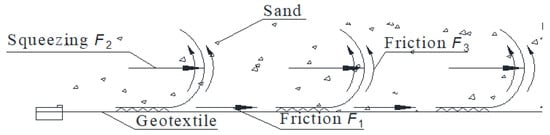
Figure 11.
Schematic diagram of reinforcement effect of stitched rib geotextile.
According to Figure 10 and Figure 11, the contribution percentage of the underlying layer and the transverse ribs to the overall shear stress can be obtained, as shown in Table 5. It can be seen that when the normal stress is low (25 kPa), the transverse rib F2 + F3 plays a greater role, the percentage of which, under the three working conditions, is 57.5%, 69.1%, and 72.6%, respectively. As the normal stress increases, the friction effect between the underlying geotextile and the sand F1 is enhanced, and the percentage of F1 in shear stress gradually increases. When the normal stress is 150 kPa, F1 plays a more significant role, the rate of which is 70%, 61.4%, and 50%, respectively. Taking the geotextile stitched with three transverse ribs, for example, as shown in Figure 12, it can be seen that the reinforcement effect of the geotextile is mainly from the transverse rib at 25 kPa. With the increase of normal stress, shear stress provided by both the underlying geotextile and the transverse rib gradually increases. At 150 kPa, the shear stress provided by both is essentially the same. It can be summarized as follows: transverse ribs play a large role when normal stress is low, but the friction force of the underlying fabric requires a large normal force; therefore, as the number of transverse ribs increases when the normal stress is the same, the fraction of shear stress provided by the transverse ribs gradually increases.
Table 5.
Comparison of reinforcement effect of each part of geotextile.
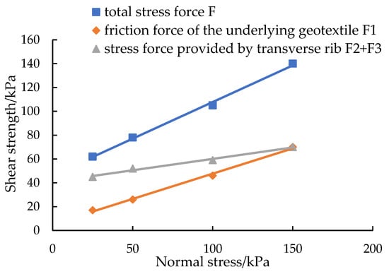
Figure 12.
Comparison of reinforcement effect of each part of geosynthetics.
4. Conclusions
Considering conventional geotextiles have a limited reinforcement effect due to the insufficient friction strength between geotextiles and soils, this paper proposes a novel type of geotextile with stitched transverse ribs. Large-scale direct shear tests have been carried out, and the improvement characteristics between conventional geotextiles, geogrids and the novel geotextiles have been studied. The following conclusions can be drawn.
- (1)
- Geotextile B exhibits the best reinforcement effect among the four conventional geotextiles, and the shear strength of geotextile B is 20% higher than that of pure sandy soil. Moreover, the surface of geotextile B is rough enough to provide larger friction and form a certain embedded locking effect with sandy soil when geotextile B is compared with geotextiles C and D. Geotextile B has a greater thickness, higher strength and better reinforcement effect compared with the woven geotextile A. However, geogrid shows a better reinforcement effect than the four conventional geotextiles.
- (2)
- The shear strength of the novel geotextile with stitched transverse ribs is significantly increased. When the number of ribs increases, the magnitude of stress and the friction angle increase, but the cohesion does not significantly change. When the shear displacement is small, the shear strength of the novel geotextile with three ribs is higher than that of the geogrid. However, when the shear displacement becomes larger, the shear strength of the novel geotextile is higher than that of the geogrid, indicating that the novel geotextile exhibits a very good reinforcement effect.
- (3)
- The frictional resistance from the underlying fabric, the locking effect, the transverse restraint effect, and the frictional effect of ribs contribute to the novel geotextile’s shear strength. When normal stress is low, the transverse rib is the key stress part of the geotextile, and the overall reinforcement effect is mainly from the transverse rib while the friction force of the underlying fabric requires a large normal force.
Author Contributions
Conceptualization, W.L.; data curation, H.L.; funding acquisition, G.Y.; investigation, W.L. and H.L.; project administration, W.L.; supervision, W.L.; validation, Y.Y. and Z.D.; writing-original draft, W.L., H.L. and P.X.; writing–review and editing, H.W. and Z.W. All authors have read and agreed to the published version of the manuscript.
Funding
This work was funded by the National Key R&D Program of China (No. 2022YFE0104600).
Institutional Review Board Statement
Not applicable.
Informed Consent Statement
Not applicable.
Data Availability Statement
All data have been included in the article.
Conflicts of Interest
The authors declare no conflict of interest.
References
- Chen, J.F.; Li, H.L. Research status and prospect of interface properties of geosynthetics reinforced soil. J. Undergr. Space Eng. 2009, 5, 1049–1054. [Google Scholar]
- Markiewicz, A.; Koda, E.; Kawalec, J. Geosynthetics for Filtration and Stabilisation: A Review. Polymers 2022, 14, 5492. [Google Scholar] [CrossRef] [PubMed]
- El-kady Mahmoud, S.; Azam, A.; Yosri Ahmed, M.; Nabil. Modelling of railway embankment stabilized with geotextile, geo-foam, and waste aggregates. Case Stud. Constr. Mater. 2023, 18, e01800. [Google Scholar] [CrossRef]
- Dabir, V.; Khare, K.; Munireddy, M.G. A Composite Permeable Sloping Seawall for Effective Energy Dissipation: A Quasi-Soft Alternative Solution for Shore Protection. J. Mar. Sci. Eng. 2022, 10, 1423. [Google Scholar] [CrossRef]
- Sinha, P.K.; Raj, A.; Kumar, S.; Singh, D. Mechanical Behavior of Geotextile and Geogrids on Soil Stabilization: A Review. Recent Adv. Mech. Eng. 2023, 299–308. [Google Scholar] [CrossRef]
- Wysokowski, A. Influence of single-layer geotextile reinforcement on load capacity of buried steel box structure based on laboratory full-scale tests. Thin-Walled Struct. 2020, 159, 107312. [Google Scholar] [CrossRef]
- Mosallanezhad, M.; Alfaro, M.C.; Hataf, N.; Sadat Taghavi, S.H. Performance of the new reinforcement system in the increase of shear strength of typical geogrid interface with soil. Geotext. Geomembr. 2016, 44, 457–462. [Google Scholar] [CrossRef]
- Mehmet, S.; Selçuk, A. Experimental investigation of influence of clay in soil on interface friction between geotextile and clayey soil. Arab. J. Geosci. 2020, 13, 342. [Google Scholar]
- Fattah Mohammed, Y.; Salim Nahla, M.; Ismaiel Mohammad, S. Influence of Geogrid Reinforcement of Sand in Transfer of Dynamic Loading to Underground Structure. IOP Conf. Ser. Earth Environ. Sci. 2021, 856, 1–10. [Google Scholar]
- Nunes, G.B.; Portelinha, F.H.M.; Futai, M.M.; Yoo, C. Numerical study of the impact of climate conditions on stability of geocomposite and geogrid reinforced soil walls. Geotext. Geomembr. 2022, 50, 807–824. [Google Scholar] [CrossRef]
- Lin, H.; Tang, S.; Xia, Y.; Zhou, Q. Shear behavior of geotextile tailings interface under fold condition. J. Nat. Disasters 2021, 30, 147–154. [Google Scholar]
- Chen, R.; Li, B.; Hao, D.X.; Gao, Y.C. Simulation method of geogrid reinforcement soil interface based on cohesion model. Chin. J. Geotech. Eng. 2020, 42, 934–940. [Google Scholar]
- Chen, J.F.; Li, H.L.; Liu, J.X.; Zhou, J. Study on meso-interface properties of geogrids and sand. Rock Soil Mech. 2011, 32 (Suppl. S1), 66–71. [Google Scholar]
- Bao, C.G. Research and experimental verification of interface properties of geosynthetics. Chin. J. Rock Mech. Eng. 2006, 25, 1735–1744. [Google Scholar]
- Eyyüb, K. Factors Effecting the Shear Strength of Geotextile Reinforced Compacted Clays. Dokuz Eylül Üniversitesi Mühendislik Fakültesi Fen Ve Mühendislik Derg. 2018, 20, 725–742. [Google Scholar]
- Aliyeh, A.N.; Ali, L.; Piltan, T.S. Influence of particle shape on the shear strength and dilation of sand-woven geotextile interfaces. Geotext. Geomembr. 2017, 45, 54–66. [Google Scholar]
- Guo, W.; Chu, J.; Zhou, B. Method to increase seam efficiency for woven geotextile materials. Geosynth. Int. 2015, 22, 404–410. [Google Scholar] [CrossRef]
Disclaimer/Publisher’s Note: The statements, opinions and data contained in all publications are solely those of the individual author(s) and contributor(s) and not of MDPI and/or the editor(s). MDPI and/or the editor(s) disclaim responsibility for any injury to people or property resulting from any ideas, methods, instructions or products referred to in the content. |
© 2023 by the authors. Licensee MDPI, Basel, Switzerland. This article is an open access article distributed under the terms and conditions of the Creative Commons Attribution (CC BY) license (https://creativecommons.org/licenses/by/4.0/).