1. Introduction
As an important strategic weapon, the underwater vehicle has the advantage of good concealment and plays an extremely important role in spatial three-dimensional warfare [
1]. When the underwater vehicle is sailing, most of the heat generated by the nuclear reactor will be released into the seawater, resulting in a thermal wake behind the body that is difficult to disappear, and the thermal wake will rise to the ocean surface to form hot spots of high temperature [
2]. With the development of infrared submarine exploration technology in the military field, the temperature difference of 0.001 °C on the ocean surface can be detected, which undoubtedly greatly reduces the concealability of underwater vehicles [
3].
A lot of theoretical and experimental research has been carried out on the thermal wake of underwater vehicles. In [
4], the author took the cooling water as a floating jet with momentum and studied the motion track and attenuation characteristics of the hot jet in uniform and stratified flow. In [
5], the author adopted particle tracking technology to realize flow field visualization and observed the motion trajectory of underwater vehicle wake. In [
6,
7,
8,
9], the author studied the turbulent wake generated by underwater momentum disturbance, underwater sphere, surface ship and submarine, and systematically revealed the formation process of thermal wake and the change law of wake velocity and temperature. In [
10], the author analyzed the interaction between turbulent vortex and water surface caused by wake evolution and obtained the changes of velocity field and turbulent kinetic energy field on free surface. Domestic scholar Yang [
11] took the lead in establishing the thermal wake measurement platform. Then, under the conditions of geometric similarity, similar heat flow and similar temperature field, Yang [
12], Zhang [
13] and Lai [
14] successively conducted thermal wake infrared detection experiments of underwater vehicles under direct navigation conditions. The floating process of thermal wake is divided into near wake section, transition section and far wake section.
Domestic and foreign scholars on the numerical simulation of underwater vehicle thermal wake mainly focus on the numerical simulation method, wake formation mechanism, floating diffusion and temperature attenuation law, surface infrared characteristics of influencing factors and so on. In [
15], the author obtained the distribution of wake velocity field of underwater vehicle under rotating condition by numerical calculation. In [
16], the author used the LES numerical simulation method to observe the vortex structure of wake evolution. Domestic scholars Wu [
17], Dai [
18] and Zhang [
19] conducted two-dimensional simulation on the thermal wake emission of underwater vehicles under direct navigation condition. Wang [
20], Wu [
21] and Wang [
22] conducted three-dimensional simulation on the thermal wake emission of underwater vehicle under direct navigation condition to simulate the three-dimensional vortex structure of wake. The floating diffusion process and surface temperature characteristics of thermal wake are analyzed. Zhang [
23] adopted the inflow method, Wang [
24] adopted the overlapping grid method, and Gui [
25] used four numerical methods to simulate the floating of underwater vehicle’s thermal wake. Through qualitative and quantitative analysis, the following results were obtained: drainage method and slip grid method strengthened the energy and mass transfer process. The overlap grid technology and moving grid technology strengthen the temperature characteristics of wake flow. In [
26], the author numerically simulated the rotation condition of the underwater vehicle and obtained the velocity distribution and vortex morphology of the flow field. In [
27,
28,
29], the boundary conditions and water environment also had certain influences on jet entraining. When jet is close to the boundary, “adhesive jet” will be generated due to the influence of boundary effect, that is, the existence of boundary will increase the volume flux of jet entraining, while water environment can inhibit and weaken jet diffusion. To some extent, the asymmetric characteristics of jet diffusion can be reduced or even eliminated, and the entrainment and mixing characteristics of jet flow can be changed.
In view of this, there have been in-depth theoretical and experimental studies on the thermal wake characteristics of underwater vehicles in direct navigation, but most of them have not considered the impact of rotary motion on the wake. Rotary motion is an important form of the space maneuverability of underwater vehicles and an effective way to get rid of enemy tracking. In this paper, the overlapping grid technology will be used to carry out the numerical simulation research of underwater vehicle rotating motion in uniform fresh water, explore the mechanism of thermal wake floating and diffusion under rotating motion, analyze the influence of rotary motion on the surface temperature anomaly area caused by thermal wake, and provide theoretical research ideas for reducing the risk of underwater vehicle being detected by infrared.
2. Mathematical Models and Numerical Simulation Methods
2.1. Mathematical Model
In this paper, the scaled-down model of underwater vehicle is taken as the research object, and the rotary motion of underwater vehicle is simulated. To comply with the conservation law of physics, the following equations should be satisfied:
Consider the effect of thermal wake lift force, momentum equation:
Among them, the unit of density is kg/m3, the unit of temperature T is K, the unit of viscosity is Pa·s, the unit of thermal conductivity is W/m·K, the unit of velocity component along the X and Y directions is m/s, the unit of gravity acceleration gi is m/s2, and the unit of specific heat capacity at constant pressure cp is J/(kg·K).
Due to the influence of disturbance of hull and enclosure, cooling water discharge and boundary conditions, the upwelling and diffusion process of submarine wake is a very complicated turbulent motion. The vortex motion can be better simulated by using the realizable k-ԑ turbulence model. The equation of turbulent energy is as follows:
The equation of specific dissipation rate is
Among them, G
k is the turbulent kinetic energy caused by the average velocity gradient and G
b is the turbulent kinetic energy caused by buoyancy. σ
k is the turbulence Pr number of turbulent kinetic energy, and σ
ε is the turbulence Pr number of the dissipation rate. The expression is as follows:
2.2. Physical Model
Referring to the SUBOFF model published by DTRC, this paper uses SpaceClaim to establish a three-dimensional underwater vehicle model with appendages. The size ratio is reduced by about 1:90, and the model size parameters are as follows in
Table 1. In order not to affect the wake development scale of underwater vehicle after turning, a 10 m × 6 m × 0.8 m water computational domain is established, which is along the X, Z, Y directions.
As shown in
Figure 1, the underwater vehicle rotates in uniform fresh water at an angular velocity of 0.0524 rad/s, with a radius of rotation of 3.82 m, and it takes 60 s to complete 180° rotation. The control cooling water discharge speed is 0.1 m/s, and the cooling water temperature is 350 K. The cooling water outlet is set as the velocity inlet, the water surface as the pressure outlet, and the walls around the calculation domain as the symmetric wall, and the interface between the underwater vehicle and the sea area is set as the overlapping interface.
2.3. Mathematical Model
In order to improve the simulation accuracy, the overlapping mesh technology is used to simulate the underwater rotary motion of the underwater vehicle. The computing domain is used as the background grid, which is divided into structured grids by ICEM. As shown in
Figure 2, the underwater vehicle, as a component grid, is divided into unstructured grids mixed with polyhedra and hexahedron by Fluent Meshing, and the circular discharge outlet of cooling water is meshed. The component mesh is inserted into the background mesh to complete the overlapping mesh construction as shown in
Figure 3, which ensures the mesh quality during the component movement.
Mesh independence verification verifies the sensitivity of the calculated results to the density of the mesh. The denser the grid, the more accurate the results and the longer the computation cycle, but the computing resources are limited. By constantly changing the density of the grid and observing the change of the calculation results, the grid independence can be verified if the change range is within the permissible range. The underwater vehicle was rotated for 30 s, and four sets of total grids with the number of units varying from 4.45 million, 5.45 million, 6.45 million and 7.45 million were adopted. The YZ section of 0.3 m behind the body at the initial position of the underwater vehicle was selected.
Figure 4 shows the change of thermal wake center temperature on the section with the density of the grid. It can be seen that when the number of grids is greater than 6.45 million, the calculated thermal wake center temperature of the cross section will no longer change significantly with the increase in the number of grids, satisfying the grid-independent condition.
During the simulation calculation, the realizable k-ԑ turbulence model, using the finite volume method for the computational domain, is divided into a number of control volumes to solve the series of control equations. The engineering, turbulent kinetic energy, and specific dissipation rate are controlled using the second-order upwind scheme and coupled pressure–base and velocity–base coupling modes.
3. Experimental Verification of Numerical Simulation Method
The above numerical simulation method is used to simulate the exothermic wake of the underwater vehicle in direct navigation motion. The thermal wake experiment platform of underwater vehicle was built, and the experimental results were compared with the simulation results so as to verify the reliability of the numerical simulation method, and provide theoretical support for the subsequent numerical simulation of rotary motion of underwater vehicle.
The experimental platform is mainly composed of a thermal wake generator and measuring device. The thermal wake generator is mainly composed of an underwater vehicle scale model, experimental tank, trailer system and cooling water discharge system.
Figure 5 shows the experimental model of an underwater vehicle, the size of which is consistent with the simulation model in
Table 1.
Figure 6 shows the experimental pool, and
Figure 7 shows the cooling water discharge device, which is fixed on the electric trailer. Thus, the experimental simulation of an underwater vehicle discharging cooling water is realized.
The thermal wake measuring device is composed of an infrared water surface detection system and a wake display system. As shown in
Figure 8, a Ferrier high-precision infrared thermal imager is used to conduct thermal imaging on the water surface to observe the temperature distribution of the water surface, and a magenta staining agent is used to observe the trajectory of the thermal wake for high-temperature hot water.
Figure 9 shows the water surface temperature field obtained by infrared thermal imager and numerical simulation software when the underwater vehicle is at a speed of 0.1 m/s and a time of 90 s. By comparison, when the hot wake floats to the surface of the water, the surface temperature anomaly area obtained by the experiment and simulation has a high similarity in shape and size. Both of them are composed of two discontinuous high temperature hot spots. The area of the high temperature anomaly area decreases with the increase in the horizontal distance from the underwater vehicle, and there is a low temperature narrow area in the middle.
In order to verify the accuracy of the simulation, the thermal characteristics of the abnormal water surface temperature area were quantified, intercept line AB at the center of the pool and the temperature distribution curve of line AB in
Figure 9 was obtained. As shown in
Figure 10, the temperature distribution curves of straight-line AB obtained by experiment and simulation are all saddle-shaped, which proves the existence of a low-temperature narrow area. The width of the abnormal area of water surface temperature measured by experiment is 1.3 m, and the width obtained by simulation is 1.1 m, the deviation is 0.2 m, and the relative error is 15.4%. The peak temperature in the abnormal area of water surface temperature difference measured by experiment is 295.1 K, and the peak temperature obtained by simulation is 295.175, with a deviation value of 0.025 K.
As shown in
Figure 11, the floating trajectory of thermal wake obtained by experiment and simulation has a high consistency in floating Angle and floating form. It can be seen that the cooling water, after ejection from the outlet, has a downward velocity component, and then begins to float backward and upward under the influence of buoyancy to develop into a disorderly turbulent motion, and the farther the distance from the underwater vehicle, the greater the upper and lower width of the thermal wake.
By quantifying the thermal characteristics of the water surface and the morphology of the floating trajectory of the specific thermal wake, it can be found that the simulation results are highly consistent with the experimental results, and the numerical simulation method is reliable.
4. Analysis of Simulation Results
4.1. Trajectory Analysis of Near-Field Cooling Water Movement
Figure 12a,b show the cooling water movement track of the underwater vehicle under the condition of direct flight and 90° rotary motion, respectively. It can be seen that the trajectory of cooling water in the direct flight state is distributed along the central axis of the underwater vehicle, and the cooling water rises upward after being discharged from the discharge ports on both sides. The trajectory of cooling water in the rotating state is asymmetrical. Compared with the direct flight, the cooling water in the rotating side aggravates the upward movement trend and flows through the left rudder, while the cooling water trajectory measured by the backflow moves down obviously.
In order to explore the cause of the difference in the trajectory of cooling water under the two states of the underwater vehicle, the velocity vector graphs of multiple cross sections under the two states were observed.
Take the motion state of the model with a rotation angle of 90°, and take cross-sections 1 and 2, respectively, at 0.1 m before and 0.2 m after the discharge outlet along the XY direction.
Figure 13 is the velocity vector diagram of cross-sections 1 and 2 of the underwater vehicle under the rotation state, where the color variable in
Figure 13b is temperature.
As can be seen from
Figure 13a, under the influence of the model shell and turtle back, the center of the vortex on both sides is asymmetrical, and the rotation direction is different. The rotary side vortex rotates counterclockwise, and the back flow measurement vortex rotates clockwise.
As can be seen in
Figure 13b, as the diameter of the contact surface between the model tail and water gradually decreases, due to the body volume effect, a low-pressure area appears at the location where the body diameter decreases, and the surrounding water quickly fills the “volume gap” left by the underwater vehicle movement. In addition, the disturbance effect of the shell and turtle back on the water decreases, making the vortex center offset upward. The trajectory of the high temperature cooling water discharged by the underwater vehicle is greatly affected by the vortex, which is similar to the trend of the vortex. The cooling water on the left side of the body is located in the whirling vortex and is driven upward. However, the cooling water on the right side of the body first rolls down with the deviating vortex, and then gradually moves toward the fuselage, which explains the reason for the asymmetric movement of the cooling water trajectory in
Figure 12b.
4.2. Spatial Evolution of Far-Field Thermal Wake
When the underwater vehicle is rotating, the cooling water moves asymmetrically near the body and gradually develops into a strong asymmetric thermal wake after it breaks away from the body. The thermal wake on the rotating side is above the thermal wake on the deviating side. In this section, the coupling effect of thermal wake and turbulent wake is analyzed by taking the underwater vehicle rotating 90° as an example, and the spatial evolution of thermal wake after it is separated from the body is discussed.
Dz is defined as the horizontal distance after leaving the underwater vehicle in the negative direction of the Z-axis, the thermal wake center is defined as the position with the highest temperature of the thermal wake, and the height coordinate Y of the underwater vehicle axis is 0.
As shown in
Figure 14, cross sections were taken along XY direction at distances of 0.5 m, 1.0 m, 1.5 m, 2.0 m, 2.5 m and 3.0 m from the rear of the body, and temperature and velocity vector diagrams at different cross sections were observed.
Figure 15 is the variation diagram of the height of thermal wake center with the distance of DZ from the rear of the body. Combined with
Figure 14 and
Figure 15, it can be seen that the thermal wake center on the revolving side has experienced the process of rising, sinking and then rising, and the cross-section shape in XY direction has successively developed into oval, kidney and oval. The center of the thermal wake on the deviating side went through the process of sinking and rising successively, and the shape of the cross section in the XY direction changed from circular to elliptical. The diffusive area and central rising velocity of the deviating side thermal wake in the XY direction are smaller than those of the rotating side thermal wake.
There is a great difference in the spatial evolution of the thermal wake on both sides because the buoyancy of the thermal wake is mainly affected by the vortex and the buoyancy caused by the temperature difference. When the horizontal distance from the body is more than 1.5 m, the fluid velocity in the vortex is large, and the thermal wake on both sides follows the vortex. When the horizontal distance from the body is less than 1.5 m, the strength of the vortex gradually decreases with the distance from the underwater vehicle, and the thermal wake floats under the dual influence of the vortex and the buoyance force, and the buoyance speed decreases nonlinearly.
Figure 16 shows the variation of the center temperature of the thermal wake as a function of the distance behind the body. It can be found that from the discharge to the beginning of leaving the body, the heat wake has a drastic energy exchange with the surrounding seawater, and the temperature decreases rapidly. In the process of spatial evolution of the thermal wake, the temperature of the thermal wake on the rotating side is always lower than that on the deviating side, which is related to the different intensity of the vortices on both sides. In the rotating side vortex, the fluid velocity is high, the vortex intensity is high, and the heat transfer between the thermal wake on the rotating side and the surrounding sea water is strong. With the distance from the underwater vehicle, the temperature of the thermal wake center further attenuated and finally tended to be slightly higher than that of the water body.
As shown in
Figure 14, five horizontal lines are taken from bottom to top in the six sections behind the underwater vehicle, which are, respectively, 0.5 m, 0.4 m, 0.3 m, 0.2 m and 0.1 m away from the water surface, and named Lines1–5.
Figure 17 shows the distribution of line temperature. Observing the temperature distribution of the five lines, it can be found that the farther away from the body, the larger the X-direction development scale of the thermal wake on both sides, the more the temperature attenuation, and the smaller the temperature difference with the surrounding seawater.
The double temperature peaks on Line3 in
Figure 17b indicate that the thermal wake on the revolving side floats in a kidney shape. The thermal wake on the revolving side draws the seawater coil with lower temperature into the center, making the temperature distribution of Line4 in
Figure 17c appear bimodal. In
Figure 17e, the temperature double peak of Line3 is caused by the thermal wake floating on the deviating side rising to the water depth and the thermal wake floating on the rotating side just leaving the water depth. Line5 in
Figure 17f shows that when the thermal wake of the revolving side mixed with low temperature seawater floats to 0.1 m above the water surface, the temperature distribution is irregular, and the X-direction development scale reaches 1.2 m.
4.3. Analysis of Water Surface Temperature Field
By observing
Figure 14f, it can be seen that when the underwater vehicle rotated in the water for 30 s, the thermal wake did not rise to the surface. Therefore, when studying the variation law of water surface temperature difference caused by the thermal wake, the working condition of 70 S of the underwater vehicle was adopted in this section.
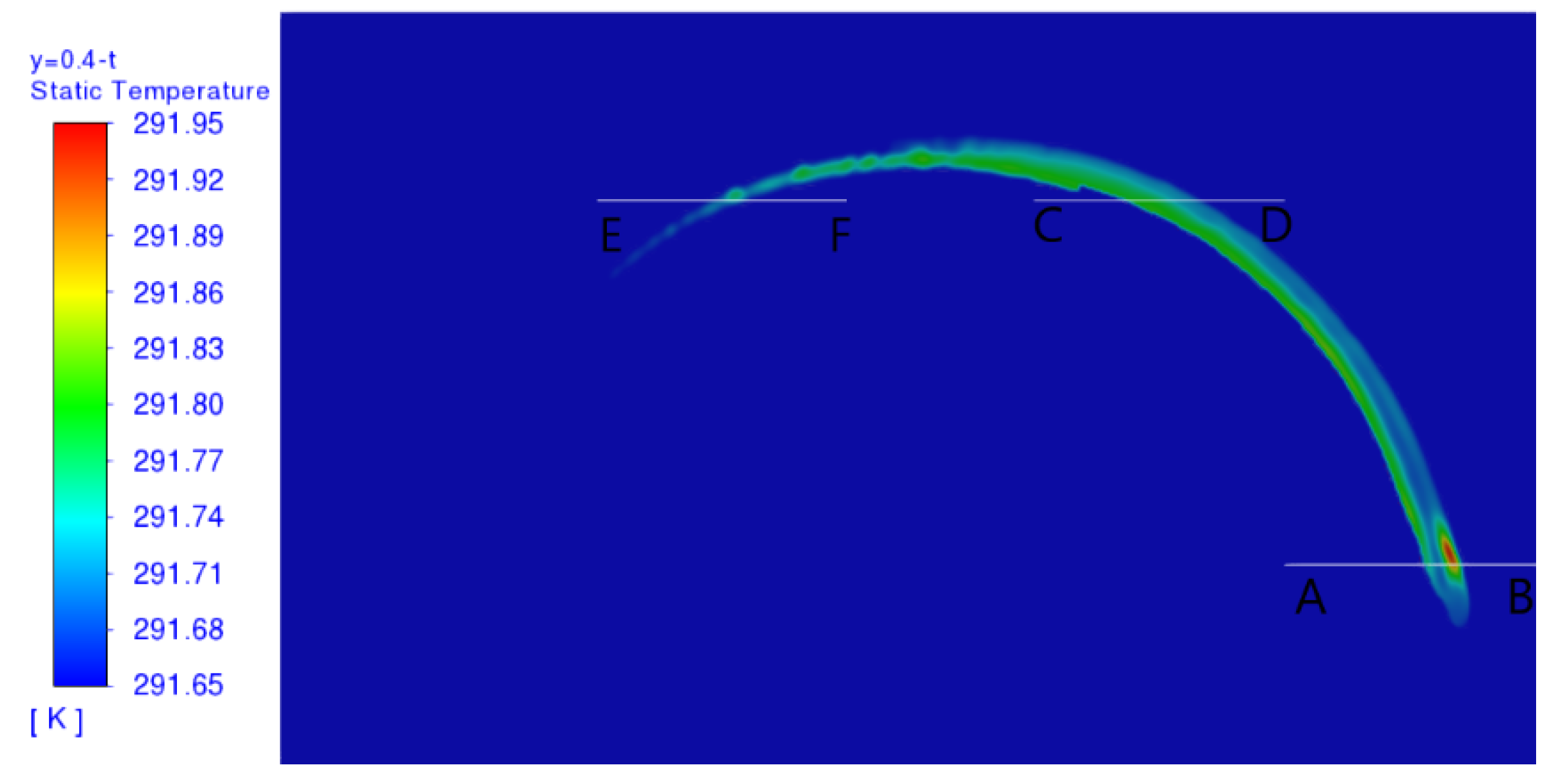
Figure 18 shows the surface temperature field of the underwater vehicle during 70 S slewing, in which three straight lines AB, CD and EF are selected. The temperature anomalous area is defined as the water surface area with temperature higher than 291.65 K. There is an arc-shaped temperature anomalous area on the water surface, which is composed of two high-temperature hot spots with an area of 2.627 m
2. By observing the temperature and width of the two hot spots near the three lines, it can be found that the characteristics of the hot spots on the rotating side experience a process from weak to strong and then decay, and the hot spots on the deviating side gradually increase.
Cross sections were taken along the YZ direction at the lines AB, CD and EF, and the temperature cloud and velocity vector diagrams of the three sections are shown. The color variable is temperature. In
Figure 19, the widths of the hot spot on the rotating side are 0.25 m, 0.45 m and 0.12 m, respectively, and the widths of the hot spot on the deviating side are 0 m, 0.13 m and 0.19 m, respectively.
The earliest abnormal area of water surface temperature is near line AB.
Figure 20 shows the curve of the maximum difference ΔT between the temperature on the line and the water surface with time. When the underwater vehicle is rotating, the development process of thermal wake is divided into three stages: thermal wake floating, mixing of thermal wake on the rotating side, and mixing of thermal wake on the deviating side. In the first stage, the variation range of ΔT is small, and the thermal wake does not rise to the water surface to cause the abnormal area of water surface temperature. In the second stage, the thermal wake on the deviating side is still in the rising stage, while the thermal wake on the rotating side is undergoing intense heat transfer with the water surface, and ΔT increases rapidly. At 55 s, the temperature anomaly characteristics of the thermal spot on the rotating side begin to decay, and ΔT decreases. In the third stage, the deviation side thermal wake floats to the water surface in 60 s, and the deviation side hot spot begins to appear on the water surface. Since the temperature of the deviation side thermal wake is higher than that of the rotation side thermal wake, ΔT continues to increase, and then the decay speed of ΔT gradually decreases with time, and ΔT decreases to 0 K after a long enough time.


