Abstract
This paper investigates if the polar groups induced by a plasma treatment can increase the lap shear strength of laser-joined metal and plastic hybrids. Optimal laser joining parameters for cold-rolled AISI304–polyamide 6.6 and sandblasted AISI304–polypropylene hybrids were developed at 2.85 MPa and 4.22 MPa, respectively. The surface free energy was doubled for all used plasma gases to a value of ca. 80 mN m−1 at 180 s. The plasma-treated samples were joined and tested. The arithmetic means of the plasma-treated hybrids’ lap shear strength with polyamide 6.6 varied slightly, but all measured values were within the range of the untreated samples. Residue on the sheared metal samples indicated covalent bonds between AISI304 and polyamide 6.6. The lap shear strengths of the plasma-treated polypropylene hybrids were significantly reduced between −30.8% and −53.3%, depending on the used plasma gas. This was attributed to the over-aging and development of low-molecular-weight oxidized materials, which led to a weak boundary layer. No residue of polypropylene was found on treated or untreated lap shear samples. No correlation between the surface free energy and lap shear strength could be found.
1. Introduction
The combination of metals and plastics enables the formation of high-strength and lightweight structures via the combination of the low density, corrosion, and oxidation resistance of plastics with the extraordinary mechanical properties of metals. Typical applications for these hybrids include the automotive industry [1], aerospace industry [2] or in the field of healthcare [3]. Common joining technologies for plastic–metal hybrids are mechanical joining processes [4,5,6], adhesive bonding [7,8,9] and direct thermal joining. Among the thermal joining methods, alongside induction [10] or ultrasound [11], lasers can be used to join metals to thermoplastics [12,13,14]. In recent years, the combination of laser and ultrasound was also investigated [15]. Due to the highly efficient and non-contact energy input via laser, this field of research received great attention relating to direct thermal joining processes.
Kawahito et al. were the first research group to investigate the application of lasers in 2006 and defined the term laser-assisted metal and plastic (LAMP) joining. They used different types of lasers to join AISI 304 with amorphous polyamide, polyethylene terephthalate, polycarbonate and polypropylene with at least 80% transmissivity. With polypropylene as an exception, sound joints were created [16]. The joints can be bonded via direct or indirect measures. When employing the direct method, the laser is transmitted through the thermoplastic, heating the interface between the polymer and metal [17]. Indirectly, the laser heats the backside of the metal, transferring the heat through the cross-section of the metal substrate via heat transfer. In both cases, the polymer plasticizes and wets the metal substrate [18]. The schematic of these joining processes is shown in Figure 1. Pressure during the joining process is necessary to ensure good contact between the metal surface and the molten plastic.
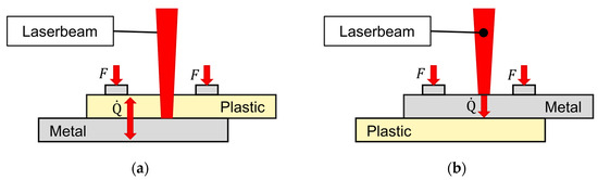
Figure 1.
Schematic figure of (a) direct and (b) indirect laser-assisted metal and plastic (LAMP) joining.
To improve the bonding strength, different kinds of surface pretreatments were investigated. Some research groups used laser ablation to create grooves in the metal substrate to improve mechanical adhesion. Schricker et al. could increase the tensile strength of an AISI 304–polyamide 6 at 2.1 MPa to 11.3 MPa by laser-structuring the steel surface [19]. Furthermore, other investigations revealed that additional adhesion theories alongside mechanical adhesion occur in laser-joined metal and plastic hybrids. XPS measurements showed that a chemical bond between polyamide and AISI 304 exists due to increased peaks of chromium and oxygen, indicating the creation of chromium oxide [16]. Katayama and Kawahito identified a possible chemical bond between the chromium oxide layer of an AISI 304 steel with elements of the used polyethylene terephthalate in their laser-joined hybrids [20]. Hirchenhahn et al. created aluminum–polyamide 6.6 hybrids via laser-joining. They identified that the chemical bond formed was a carbon–oxygen–aluminum bond. One of the possible reaction sides is the double oxygen bond of the amide group in polyamide 6.6. This indicates that polymers with polar groups like polyamide 6.6 are capable of creating chemical bonds at the interface [21,22]. X-ray mappings performed by Amne Elahi et al. on a laser-joined 1050−H24 aluminum alloy with polyamide 6.6 with a laser-polished or laser-ablated surface also showed physiochemical bonding between aluminum oxide and polyamide 6.6 at the interface [23]. Huang et al. investigated the bonding mechanisms of laser-joined AISI 304–PMMA hybrids. They used a pulsed laser with an area energy of 20.16 J mm−2 to achieve a maximum lap shear strength of 4.17 MPa. They identified M−O and M−C chemical bonds and mechanical anchoring of the molten plastic on the steel’s surface as the main contributions to the adhesive strength [24]. Al-Sayyad et al. used a low-pressure plasma treatment before joining aluminum and polyamide by means of indirect laser-joining. They used a mixture of oxygen and nitrogen as the plasma gas. The shear load increased when the polyamide or the aluminum was treated and maximized with the treatment of both surfaces. The rise in shear resistance correlated with the rise in surface free energy. This research leads to the hypothesis that the thermodynamic theory of adhesion and the surface free energy correlates with the lap shear strength of laser-joined metal and plastic hybrids [25].
As mentioned before, Kawahito et al. also used polypropylene for their first experiments. No sound joints could be created, resulting in a lap shear strength of zero [20]. Schricker et al. also used polypropylene for their investigation. Without the laser-ablation process of the metal substrate, no sound joint could be created. With the improved mechanical adhesion, the shear strength increased from 0 to 8.7 MPa [19]. In adhesive technologies, the surface treatments of plastics without polar groups like polypropylene is common to increase the joint strength. Low-pressure plasma treatments are used to clean and activate the surface, increasing their surface free energy significantly by producing polar groups and radicals on the surface [26]. C. Mandolfino treated the surface of polypropylene with low-pressure plasma before using an adhesive. A treatment of oxygen plasma for 180 s increased the lap shear strength by 387% from 0.56 MPa to 2.72 MPa [27].
This research investigates the influence of a low-pressure plasma treatment on the lap shear strength of laser-joined hybrids with AISI 304, polyamide 6.6 and polypropylene. Thus, the impact of polar groups or radicals on the surface of plastics with polar and nonpolar characters can be identified and compared. Additionally, the plasma gases varied between oxygen, water vapor and argon. This is due to the point that oxygen and water vapor plasma create radicals and add functional groups; argon, as an inert gas, only establishes radicals on the polymeric surface [26] (p. 25). The surface free energy is measured employing the OWRK method and correlated with the results of the lap shear strength. Additionally, the fractured surfaces are analyzed to identify possible residues due to increased covalent bonds due to the low-pressure plasma treatment.
2. Materials and Methods
2.1. Materials
The plastics used in this research were semi-crystalline polyamide 6.6 and amorphous polypropylene. These were chosen due to the polar amino group of polyamide 6.6 and the lack of any polar group in polypropylene. Figure 2 shows the chemical structure of both the plastics and polar amino group of polyamide 6.6.
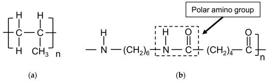
Figure 2.
Chemical structure of (a) polypropylene and (b) polyamide 6.6.
For the metal substrate, the cold-rolled steel AISI 304 (DIN 1.4301, ISO X5CrNi18−10) was chosen. For the hybrids with polyamide, the cold-rolled surface was used, while the surface of the steel was sandblasted for the hybrids with polypropylene. This was carried out because untreated polypropylene needs sufficient mechanical adhesion to create sound joints. No further surface treatment was carried out for any of the steels. The parameter set was utilized to identify the change due to the low-pressure plasma treatment. The sandblasting increased the surface roughness of the steel, which was analyzed from five measurements acquired via Tester T1000 by Hommelwerke GmbH, Villingen−Schwenningen, Germany. Mechanical adhesion is based on the form-fitting connection between the plastic and the steel. The liquid plastic penetrates the pores, capillaries, undercuts and irregularities on the steel surface. By increasing the surface roughness, additional capillaries, pores and undercuts can be created. This enhances the snap-fit effect and enables nonpolar plastics to create sound joints [28,29]. The average surface roughness is shown in Table 1.

Table 1.
Average surface roughness of the steel samples used.
An MHG SMG 50 (Düsseldorf, Germany) was utilized for the sand blasting. White corundum with a granularity varying between 150 and 212 µm, an air pressure of 4 bar at an angle of 90° with a distance between steel and blasting pistol of 50 mm was used in the process. The geometry of both materials was 50 mm × 25 mm × 2 mm. Before the joining process, the surfaces were cleaned with ethanol.
2.2. Laser Setup
A fiber laser with a maximum continuous laser power output of 250 W and a wavelength of 1080 ± 5 nm was used. The laser was mounted with a collimation unit, a beam expander and a galvanometric scanner in a constructed mount seen in Figure 3a. A f-theta lens ensured an orthogonal laser beam over the whole scanning area.
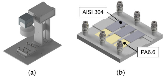
Figure 3.
CAD-generated image of the (a) laser mount with sample holder and (b) sample holder without the cover plate.
For the laser joining experiments, a specimen holder for three joints with an overlap width of 12.5 mm and an applied pressure of 0.4 MPa through compression springs was utilized, as illustrated in Figure 3b. The distance between the sample surface and the f−theta lens was maintained constant to achieve a laser spot diameter of 5 mm. A simple line was chosen as the scanning geometry, with an additional 5 mm before and after the first and last sample to ensure homogeneous heating. The indirect heating method was applied for all samples. The laser joining processes were conducted under atmospheric conditions at approximately 20 °C and 50% humidity. The variation in laser power and scanning speed is detailed in Table 2. To facilitate comparison with other LAMP publications, the laser power was divided by the scanning speed to obtain the energy input per unit length, also known as line energy. These parameters were varied in identifying conditions yielding the maximum lap shear strength with an adhesive failure mode. The investigated parameter range was determined based on experience, considering the melting ranges of different plastics and the significance of metal thickness when utilizing the indirect joining method. Thicker metals typically require higher laser power or reduced scanning speed to achieve sound joints.
Table 2.
Laser parameters used in this research.
2.3. Low-Pressure Plasma Setup
The surface treatment of the plastics was conducted using a SmartPlasma 2 low-pressure plasma system by plasma technology GmbH, Herrenberg−Gültstein, Germany. Argon, water vapor and oxygen served as working gases. The low-pressure plasma was initiated by reducing the chamber pressure to 0.05 mbar using a vacuum pump, followed by inserting the respective working gas to achieve a constant working pressure of 0.1 mbar. This is a continuous process between pumping and gas inlet to ensure a steady working pressure. The generator operates at a low frequency of 20 to 50 kHz at a power level of 80 W. The plastic substrates were exposed to the plasma for 10 s, 180 s and 600 s. Figure 4 illustrates the SmartPlasma2 low-pressure plasma reactor.
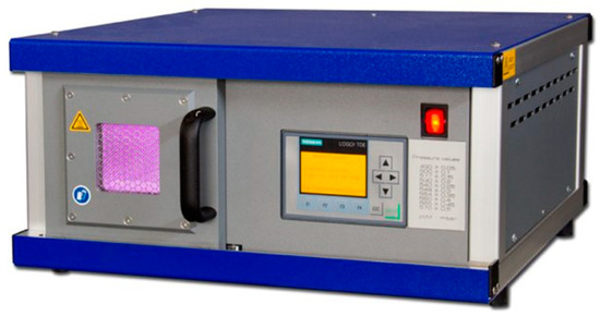
Figure 4.
SmartPlasma 2 by plasma technology GmbH [30].
2.4. Contact Angle and Surface Free Energy Measurement
To assess changes in the surface free energy resulting from the plasma treatment, the Owens, Wendt, Rabel and Kaelble method (OWRK method) was employed. This method utilizes the geometric mean value to combine polar and dispersive components, represented by the following equation.
where is the surface tension of the liquid, is the surface tension of the solid, and is the contact angle between liquid, surface and atmosphere. Superscripted letters indicate the polar or dispersive component. The work method requires at least two liquids with known surface tensions, with a required polar component of near zero for one of the liquids. In this research, demineralized water and diiodomethane were utilized. The polar and dispersive values used in this research are detailed in Table 3 [31].
Table 3.
Surface tensions of the used test liquids.
Up to 5 µL water and 3 µL diiodomethane were each deposited on the surface using a micro-syringe. Ten readings for each test liquid were taken at various locations on the treated surface. The ImageJ plugin for contact angles was employed to determine the values of the different readings. The mean wetting angle of diiodomethane was used to calculate the dispersive component of the surface free energy. With the value of the dispersive component and the wetting angle of water, the total surface free energy of the surface could be determined. The measurements were conducted at room temperature with approximately 50% humidity. A schematic of the contact angle measurement setup is illustrated in Figure 5.
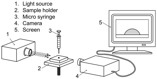
Figure 5.
Schematic of the contact angle measurements [32].
2.5. Mechanical Testing and Microstructural Analysis
Lap shear tests were carried out using an Instron E10000, Norwood, MA, USA, with a test speed of 0.5 mm min−1 at room temperature and 50% humidity. Spacers were attached at each end of the lap shear samples to ensure a parallel load. The fixation of the samples in the test setup is depicted in Figure 6.
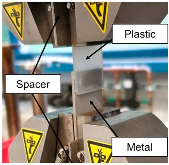
Figure 6.
Lap shear test setup and sample fixation.
Five samples were tested for each parameter set. ImageJ and a macroscope were utilized to determine the wetted area of the samples. Additionally, a DVM6 from Leica Mikrosysteme Vertrieb GmbH, Wetzlar, Germany, and the associated software Leica Application Suite X 3.0.14.23224 (Las X) was used to identify the heat-affected zone.
To identify any residue of the plastics on the metal samples, a scanning electron microscope (SEM) was employed. The JSM 7001F from Jeol GmbH, Freising, Germany, equipped with a secondary electron (ETD), backscatter electron (BSE) and energy dispersive X-ray (EDS) detectors, was used. The fractured samples investigated by the SEM were cleaned in ethanol in an ultrasonic bath. Additionally, a sputtering process was applied to coat the samples with 3 nm of gold to ensure good conductibility of the samples.
3. Results and Discussion
Figure 7 illustrates the structure of the Results and Discussion section in a flowchart, providing an overview of the different content in the subsections. Section 3.1 focuses on the development of the laser joining parameters for sandblasted AISI 304 and polypropylene, as well as cold-rolled AISI 304 and polyamide 6.6. Section 3.2. covers the low-pressure plasma treatment and the identification of the surface free energy. The results of these sections are combined to investigate the influence of increased surface free energy due to the low-pressure plasma treatment on the lap shear strength of the indirect laser-joined hybrids.
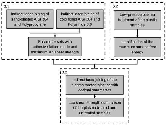
Figure 7.
Flowchart of the results and discussion section.
3.1. Identification of the Joining Parameters
The laser parameters play a significant role in the failure mode of laser-joined metal and plastic hybrids. An adhesive failure occurs when the hybrid fails directly at the interface of the joint. Increased thermal input, resulting from high laser power and low scanning speed, can damage the plastic and lead to failure inside the plastic part while the overlap joint remains intact. This is known as a cohesive failure mode [33]. An adhesive failure mode is crucial for identifying the influence of surface pretreatment on the lap shear strength. The criteria to identify the optimal parameter set include the maximum lap shear strength in combination with an adhesive failure mode. The lap shear strength of the cold-rolled AISI 304–polyamide 6.6 laser-joined hybrids is presented in Figure 8.
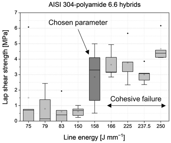
Figure 8.
Lap shear strength of the cold-rolled AISI 304—Polyamide 6.6 hybrids.
Up to a line energy of 150 J mm−1, the lap shear strength values are low. Below 83 J mm−1, some of the tested samples failed before the sample could be mounted. At 158 J mm−1, an arithmetic mean of 2.85 MPa is achieved with an adhesive failure mode in every sample. With increasing line energy, the arithmetic mean rises. Additionally, the number of cohesively failed samples increased as well. At 166 J mm−1, two of the five tested samples failed cohesively in the plastic side of the hybrid. At 250 J mm−1, the highest arithmetic mean at 4.67 MPa could be achieved, and all five of the five tested samples failed cohesively. Therefore, the maximum lap shear strength with adhesive failure mode is achieved at 158 J mm−1 with 2.85 MPa. A cross-section of the cold-rolled AISI 304–polyamide 6.6 is shown in Figure 9.
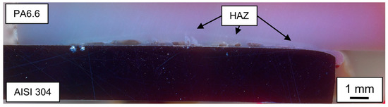
Figure 9.
Cross-section of a cold-rolled AISI 304—Polyamide 6.6 (PA6.6) hybrid joined with 158 J mm−1 with visible pores and the heat affected zone (HAZ).
In this cross-section, polyamide 6.6 is shown on top, while the steel is on the bottom—vice versa to the joining configuration. The joining process has no influence on the steel side of the hybrid. On the plastic side, different interactions are observed. At the interface, there are some voids. These voids can be attributed to the vaporization of the water content of the polyamide 6.6 or thermal degradation. Additionally, the heat-affected zone is visible due to a slightly brighter curve, overlapping on the right side of the joined area. On the top right side of the steel sample, some molten plastic is visible, which was pressed out of the overlap area during the joining process. The investigation of the cross-section shows wetting from the polyamide 6.6 melt on the cold-rolled AISI 304. However, the created voids can reduce the lap shear strength because they can function as inner notches. Figure 10 displays an adhesively and cohesively failed AISI 304–polyamide 6.6 hybrid.
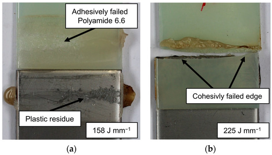
Figure 10.
Failure mechanisms of the cold-rolled AISI 304—Polyamide 6.6 samples (a) adhesive failure and (b) cohesive failure mode.
In Figure 10a, an adhesively failed cold-rolled AISI 304–polyamide 6.6 hybrid is shown, and in Figure 10b, a cohesively failed sample at a higher line energy is presented. The hypothesis is that with higher line energy, the thermal damage increases, which leads to a weakened plastic sample. This is also supported by the number of cohesively failed samples. At the line energy of 166 J mm−1, only two of the five tested samples failed cohesively, while at 250 J mm−1, every sample failed within the plastic. Also, the fraction of the plastic residue on the overlap joint increases, which can lead to a higher ratio of cohesive failure.
The adhesively failed samples show plastic residues on the steel surface, suggesting the presence of chemical bonds between the polar groups and the oxides on the steel surface, as described in the Introduction section. At line energies below 158 J mm−1, only smaller areas or no residue at all were identified on the steel samples, indicating that a certain amount of thermal energy is needed to create these chemical bonds. Further investigation of the plastic residue was conducted through SEM analysis on a lap-sheared sample, as shown in Figure 11.
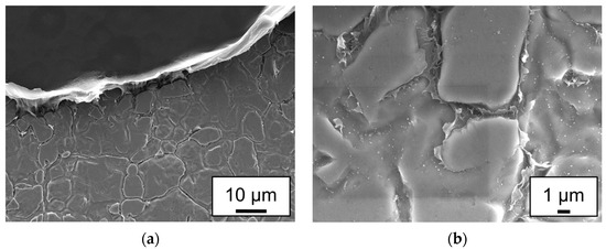
Figure 11.
ETD images of a cold-rolled AISI 304–polyamide 6.6 lap-sheared sample, joined at a line energy of 158 J mm−1: (a) Boundary between macroscopic residue and the steel surface; (b) microscopic view of the steel surface.
Figure 11a depicts the boundary between the residue and the steel surface. The plastic residue was elongated in the direction of the lap shear test, indicating some form of ductility. Additionally, Figure 11b shows the surface of the steel at a higher magnification, revealing the plastic residue between the grains, which were flattened out by the cold rolling process.
In summary, the optimal joining parameter for the indirect laser joining of polyamide 6.6 and cold-rolled AISI 304 within the scope of this experiment was at a line energy of 158 J mm−1.
Due to the lower melting point of polypropylene compared to polyamide 6.6, the overall needed line energy to create sound joints is reduced. The lap shear strength of the laser-joined sandblasted AISI 304–polypropylene hybrids is illustrated in Figure 12.
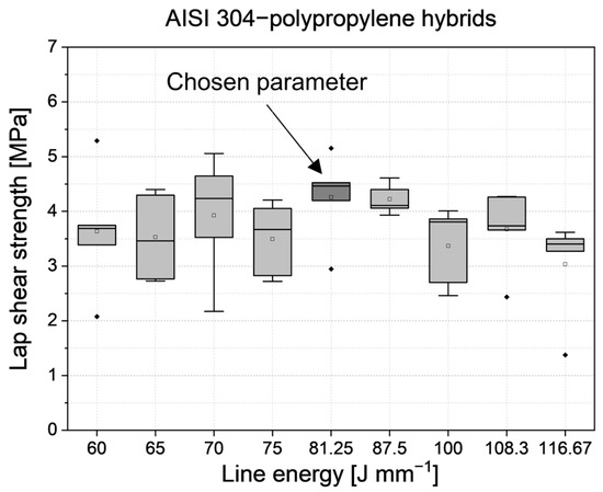
Figure 12.
Lap shear strength of the sandblasted AISI 304—Polypropylene hybrids.
The lap shear strengths of the sandblasted AISI 304–polypropylene hybrids have a clear distribution in the investigated range. The maximal arithmetic mean is achieved at 81 J mm−1 with 4.26 MPa. A slightly higher line energy can almost achieve the same value. At 88 J mm−1, the arithmetic mean of the lap shear strength is 4.22 MPa. Increasing the line energy further or reducing it below 81 J mm−1 results in a decrease in lap shear strength. Additionally, it is worth mentioning that no lap shear sample of sandblasted AISI 304 and polypropylene failed cohesively. Figure 13 shows a cross-section of a hybrid joined with 81 J mm−1.
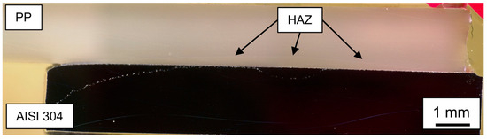
Figure 13.
Cross-section of a sandblasted AISI 304–polypropylene hybrid joined with 81 J mm−1.
In direct comparison with the polyamide 6.6 hybrids, there are no voids or pores visible, as expected due to the lack of dissolved water in polypropylene. The heat-affected zone is lower in height, has less visibility and spreads over the whole width of the sample. To investigate if residue was left on the sheared samples, a lap shear joined is shown in Figure 14a before and Figure 14b after the lap shear tests.
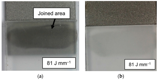
Figure 14.
Sandblasted AISI 304–polypropylene samples: (a) joined area and (b) adhesive failure.
Figure 14a shows the as-joined state of the sandblasted AISI 304–polypropylene sample. Due to the amorphous characteristic of the used polypropylene, the joined area has good visibility. Figure 14b shows the same sample that failed adhesively in the lap shear test. No residue is visible either on the steel or on the plastic side. Every lap-sheared sample at the line energy of 81 J mm−1 failed adhesively, and no macroscopic residue was visible. Additionally, lap shear samples were joined at 81 J mm−1 with cold-rolled AISI 304, and no bond could be achieved. In addition to the macroscopic analysis of the lap-sheared sample, SEM analysis was conducted on the same sample shown in Figure 14. The SEM analysis is depicted in Figure 15.
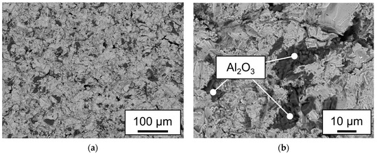
Figure 15.
BSE analysis of a sandblasted AISI 304 sample shown in Figure 14 (a) at a magnification of ×200; (b) at a magnification of ×1000 with marked areas of Al2O3 particles.
Figure 15a,b present BSE images of the sandblasted AISI 304 part of the lap-sheared sample shown in Figure 14. Dark particles are embedded within a brighter matrix. EDS measurements on both phases showed that the brighter phase consists mainly of iron, chromium and nickel, which are the main content of AISI 304 steel. The darker phase consists mainly of oxygen and aluminum, indicating that these are corundum particles embedded in the surface during the sandblasting process. No significant amount of carbon could be found in any of the measurements, which could indicate a residue of polypropylene. No sign of a possible chemical bond between the metal surface and polypropylene could be found, confirming the macroscopic investigations and the results by Kawahito and Schricker [16,19].
3.2. Surface Free Energy
As mentioned in the Introduction section, polar groups in plastic are responsible for chemical bonds in laser-joined metal and plastic hybrids. The low-pressure plasma treatment is a process that introduces these groups on the surface of plastics. Measurements of the wetting angles and the resulting surface free energy provide information about the performance of the plasma treatment. In Figure 16, two water droplets are shown on the surface of polypropylene samples. In Figure 16a, the polypropylene is untreated, while in Figure 16b, the sample was treated in an O2 plasma for 180 s.
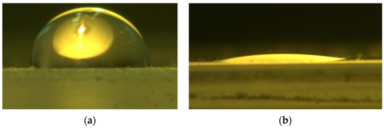
Figure 16.
Image of a water droplet on a polypropylene sample at a magnification of ×50 at the following treatment steps: (a) untreated and (b) treated with O2 plasma for 180 s.
The wetting angle of the untreated water droplet is over 90°, while the droplet on the O2 plasma-treated sample was reduced to an angle under 10°, indicating a significant increase in the polar component of the surface free energy. The measured contact angles were used to calculate the surface free energy of both plastics in interaction with every plasma gas, as shown in Figure 17.
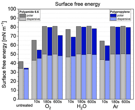
Figure 17.
Surface free energy of the low-pressure plasma and untreated plastic samples.
In an untreated state, the polar component of polypropylene is near zero. Comparing the polar component to the measurement of polyamide 6.6, the lack of polar groups in the resulting surface free energy can be seen. At every investigated time for all plasma gases, polyamide 6.6 has higher surface free energy values than polypropylene. At 10 s, the dispersive and polar components rise for both plastics. The polar component of polypropylene increases significantly in comparison to the untreated state, with water plasma showing the highest rise at 10 s compared to the other gases. At 180 s, the measured surface free energy peaks at all three plasma gases and for both polymers while dropping slightly for polypropylene at 600 s. The polyamide 6.6 samples maintain a high value at 180 s and 600 s treatment times. It is also worth mentioning that the trend of the surface free energy is similar for all used plasma gases. Due to the maximum surface free energy at 180 s, the treatment time was chosen to identify the influence on the lap shear strength.
3.3. Influence of the Plasma Treatment on the Lap Shear Strength
As written in the Introduction section, low-pressure plasma treatments, or the increase of the surface free energy in general, can increase the lap shear strength of joints bonded with an adhesive. The results of this work show that the influence differs when a thermal joining method is used. In Figure 18, the increased or reduced arithmetic means of the lap shear values are noted as percentages in comparison with the untreated samples.
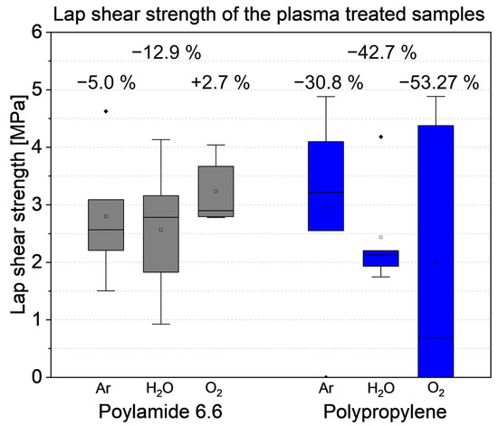
Figure 18.
Lap shear strength of the plasma-treated samples.
It is evident that most plasma treatments result in a reduction in the lap shear strength. The O2 treatment of polypropylene led to a 53.27% decrease, with some of the samples failing when subjected to testing. The Ar treatment of polypropylene reduced the lap shear strength by only 30.8%, while the water−plasma decreased it by 42.7%. The surface free energy of all investigated polypropylene samples was nearly at the same level, and this was also observed for the polyamide 6.6 samples. Although the arithmetic mean values varied among all plasma-treated samples, the entire box plots have similar values. Ar and H2O plasma reduced the lap shear strength of the polyamide 6.6 hybrids by 5% and 12.9%, respectively, while the O2 plasma treatment increased the arithmetic mean by 2.7%.
The lap shear strength results of the plasma-treated polyamide 6.6 hybrids, despite variations in the arithmetic mean values, are within the range of the untreated samples. This suggests that increasing the surface free energy due to additional polar groups via low-pressure plasma treatment had no influence on the lap shear strength of polyamide 6.6 hybrids.
In contrast, the significant reduction in strength of the polypropylene samples is not within the range of the untreated samples in Figure 12. It is possible that the treatment induced the formation of low-molecular-weight oxidized materials, which could melt and form a weak boundary layer at the interface between steel and plastic [34,35]. To analyze the interaction between the plasma treatment and the failure mechanism, Figure 19 provides the macroscopic overview of two lap-shear-tested overlap joints treated with O2 plasma for 180 s.
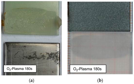
Figure 19.
Macroscopic overview of two overlap joints with O2 plasma-treated plastics for 180 s: (a) polyamide 6.6 hybrid with cold-rolled steel; (b) polypropylene hybrid with sandblasted steel.
Figure 19a shows the adhesively failed plasma-treated polyamide 6.6 sample. In comparison with the untreated sample, there are no macroscopic differences, and there was no noticeable increase or decrease of residue on the steel surface. It is worth mentioning that the number of cohesive failed samples was higher with a plasma-treated polyamide 6.6., without a significant increase in lap shear strength. On the polypropylene sample in Figure 19b, no residue or any change compared to the untreated sample can observed macroscopically. To identify possible microscopic changes, SEM measurements are shown in Figure 20.
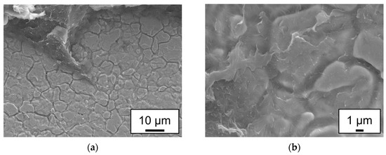
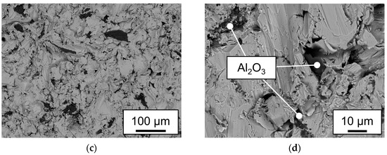
Figure 20.
SEM analysis of the steel samples of the O2 plasma-treated hybrids shown in Figure 14; (a,b) show ETD measurements of the cold rolled AISI304−polyamide 6.6 sample; (c,d) show BSE images of the sandblasted AISI304−polypropylene samples.
The polyamide 6.6 residue on the steel sample shown in Figure 20a,b appears more fractured after the low-pressure plasma treatment, suggesting a potential change in the material properties. The increased brittleness may be attributed to the reduction of water content in polyamide 6.6 during the treatment in a low-pressure atmosphere. It is known that the water content of polyamide 6.6 leads to higher ductility [36], and a low-pressure treatment could, indeed, reduce the water content, especially in the surface area. This provides an explanation for the increased brittleness and the subsequent loss of lap shear strength of the Ar and H2O−plasma-treated samples.
Figure 20c,d, showing the sandblasted steel of a plasma-treated polypropylene hybrid, indicate that the steel exhibits the same fissured surface as the untreated sample, with the same Al2O3 embedding. Importantly, no residue of polypropylene or any other additional phase could be detected. This supports the hypothesis that the polar groups added to the surface of the polypropylene samples did not create a covalent bond with the steel surface. This observation is consistent with Scheick’s postulation that the created polar groups would realign inwards during the melting process and would not increase the strength between plastic and metal [37].
4. Conclusions
The aim of this investigation was to identify the interaction between a low-pressure plasma treatment and the lap shear strength of laser-joined metal and plastic hybrids. The focus was on understanding the correlation between surface free energy, lap shear strength and potential residue on the surface of the metal due to covalent bonds. The achieved results can be summarized as follows:
- Nonpolar plastics, such as the polypropylene used, require sufficient mechanical adhesion when employed in a laser joining process with metals. No plastic residue was detectable on the fractured surface. The maximum lap shear strength of 4.26 MPa was achieved for sandblasted AISI304–polypropylene laser-joined hybrids at a line energy of 81 J mm−1.
- Polyamide 6.6 hybrids can be joined without mechanical adhesion on smooth surfaces. Adhesively fractured samples leave residues on the steel surface. Higher line energies can induce cohesive failure within the plastic sample. At 158 J mm−1, the cold–rolled AISI 304–polyamide 6.6 hybrids achieved 2.85 MPa with an adhesive failure mode.
- Low-pressure plasma treatments with argon, oxygen and water as plasma gases increase the surface free energy significantly. The disperse and polar values calculated by the OWRK method were at the same level at 180 s treatment time, elevating the surface free energy by a factor of 2.4 for polypropylene and 2.3 for polyamide 6.6 to ca. 80 mN m−1.
- The low-pressure plasma-treated polyamide 6.6 samples exhibited slightly varying lap shear strengths, ranging from +2.7% to −12.9%, depending on the plasma gas used. The variation was in the range of the untreated samples. The drying effect of the low-pressure treatment increased the number of cohesively failed samples. This also led to a more fractured appearance of the residue on the steel sample.
- The lap shear strength of the plasma-treated polypropylene samples decreased by 30.8% for argon plasma, 42.7% for water plasma and 53.3% for oxygen plasma. The decline was attributed to over-aging and the formation of low-molecular-weight oxidized materials on the surface.
These findings contrast with Al-Sayyad et al.’s research [25], which identified a correlation between the surface free energy and the lap shear strength of laser-joined metal and plastic hybrids. In this study, the low-pressure plasma treatment either had no effect or negatively affected the lap shear strength. Furthermore, the creation of polar groups on the nonpolar polypropylene did not lead to the formation of covalent bonds between the plastic and the steel surface.
Author Contributions
Conceptualization, C.T.; methodology, C.T.; validation, C.T. and L.W.; formal analysis, C.T.; data curation, C.T.; writing—original draft preparation, C.T.; writing—review and editing, L.W. and P.F.; visualization, C.T.; supervision, W.T. and C.H.; project administration, W.T. and C.H.; funding acquisition, W.T. and C.H. All authors have read and agreed to the published version of the manuscript.
Funding
This research was funded by the German Research Foundation (DFG, TI 343/170-1, HO 4776/57-1).
Institutional Review Board Statement
Not applicable.
Informed Consent Statement
Not applicable.
Data Availability Statement
Data are contained within the article.
Conflicts of Interest
The authors declare no conflict of interest.
References
- Zhou, Z.; Gao, X.; Zhang, Y. Research Progress on Characterization and Regulation of Forming Quality in Laser Joining of Metal and Polymer, and Development Trends of Lightweight Automotive Applications. Metals 2022, 12, 1666. [Google Scholar] [CrossRef]
- Huang, Y.; Gao, X.; Zhang, Y.; Ma, B. Laser joining technology of polymer-metal hybrid structures—A review. J. Manuf. Process. 2022, 79, 934–961. [Google Scholar] [CrossRef]
- Lambiase, F.; Scipioni, S.I.; Lee, C.-J.; Ko, D.-C.; Liu, F. A State-of-the-Art Review on Advanced Joining Processes for Metal-Composite and Metal-Polymer Hybrid Structures. Materials 2021, 14, 1890. [Google Scholar] [CrossRef]
- Lambiase, F. Joinability of different thermoplastic polymers with aluminium AA6082 sheets by mechanical clinching. Int. J. Adv. Manuf. Technol. 2015, 80, 1995–2006. [Google Scholar] [CrossRef]
- Lambiase, F. Mechanical behaviour of polymer–metal hybrid joints produced by clinching using different tools. Mater. Des. 2015, 87, 606–618. [Google Scholar] [CrossRef]
- Abibe, A.B.; Amancio-Filho, S.T.; dos Santos, J.F.; Hage, E. Mechanical and failure behaviour of hybrid polymer–metal staked joints. Mater. Des. 2013, 46, 338–347. [Google Scholar] [CrossRef]
- Feraboli, P.; Masini, A. Development of carbon/epoxy structural components for a high performance vehicle. Compos. Part B Eng. 2004, 35, 323–330. [Google Scholar] [CrossRef]
- Sarlin, E.; Heinonen, E.; Vuorinen, J.; Vippola, M.; Lepistö, T. Adhesion properties of novel corrosion resistant hybrid structures. Int. J. Adhes. Adhes. 2014, 49, 51–57. [Google Scholar] [CrossRef]
- Sadowski, T.; Golewski, P.; Zarzeka-Raczkowska, E. Damage and failure processes of hybrid joints: Adhesive bonded aluminium plates reinforced by rivets. Comput. Mater. Sci. 2011, 50, 1256–1262. [Google Scholar] [CrossRef]
- Lugauer, F.P.; Kandler, A.; Meyer, S.P.; Wunderling, C.; Zaeh, M.F. Induction-based joining of titanium with thermoplastics. Prod. Eng. Res. Devel. 2019, 13, 409–424. [Google Scholar] [CrossRef]
- Yeh, R.-Y.; Hsu, R.-Q. Development of ultrasonic direct joining of thermoplastic to laser structured metal. Int. J. Adhes. Adhes. 2016, 65, 28–32. [Google Scholar] [CrossRef]
- Cenigaonaindia, A.; Liébana, F.; Lamikiz, A.; Echegoyen, Z. Novel Strategies for Laser Joining of Polyamide and AISI 304. Phys. Procedia 2012, 39, 92–99. [Google Scholar] [CrossRef][Green Version]
- Bergmann, J.P.; Stambke, M. Potential of Laser-manufactured Polymer-metal hybrid Joints. Phys. Procedia 2012, 39, 84–91. [Google Scholar] [CrossRef]
- Tillmann, W.; Elrefaey, A.; Wojarski, L. Toward process optimization in laser welding of metal to polymer. Prozessoptimierung beim Laserstrahlschweißen von Metall mit Kunststoff. Mater. Werkstofftech. 2010, 41, 879–883. [Google Scholar] [CrossRef]
- Chen, Y.J.; Yue, T.M.; Guo, Z.N. Combined effects of temperature field and ultrasonic vibration on bubble motion in laser joining of plastic to metal. J. Mater. Process. Technol. 2021, 288, 116846. [Google Scholar] [CrossRef]
- Kawahito, Y.; Tange, A.; Kubota, S.; Katayama, S. Development of direct laser joining for metal and plastic. In International Congress on Applications of Lasers & Electro-Optics; ICALEO® 2006: 25th International Congress on Laser Materials Processing and Laser Microfabrication, Scottsdale, ZA, USA, 30 October–2 November 2006; Laser Institute of America: Orlando, FL, USA, 2006; p. 604. ISBN 978-0-912035-85-7. [Google Scholar]
- Chen, Y.J.; Yue, T.M.; Guo, Z.N. A new laser joining technology for direct-bonding of metals and plastics. Mater. Des. 2016, 110, 775–781. [Google Scholar] [CrossRef]
- Gao, M.; Liao, W.; Chen, C. Improving the interfacial bonding strength of dissimilar PA66 plastic and 304 stainless steel by oscillating laser beam. Opt. Laser Technol. 2021, 138, 106869. [Google Scholar] [CrossRef]
- Schricker, K.; Samfaß, L.; Grätzel, M.; Ecke, G.; Bergmann, J.P. Bonding mechanisms in laser-assisted joining of metal-polymer composites. J. Adv. Join. Process. 2020, 1, 100008. [Google Scholar] [CrossRef]
- Katayama, S.; Kawahito, Y. Laser direct joining of metal and plastic. Scr. Mater. 2008, 59, 1247–1250. [Google Scholar] [CrossRef]
- Hirchenhahn, P.; Al-Sayyad, A.; Bardon, J.; Felten, A.; Plapper, P.; Houssiau, L. Highlighting Chemical Bonding between Nylon-6.6 and the Native Oxide from an Aluminum Sheet Assembled by Laser Welding. ACS Appl. Polym. Mater. 2020, 2, 2517–2527. [Google Scholar] [CrossRef]
- Hirchenhahn, P.; Al-Sayyad, A.; Bardon, J.; Plapper, P.; Houssiau, L. Binding Mechanisms Between Laser-Welded Polyamide-6.6 and Native Aluminum Oxide. ACS Omega 2021, 6, 33482–33497. [Google Scholar] [CrossRef] [PubMed]
- Amne Elahi, M.; Koch, M.; Bardon, J.; Addiego, F.; Plapper, P. Failure mechanism analysis based on laser-based surface treatments for aluminum-polyamide laser joining. J. Mater. Process. Technol. 2021, 298, 117318. [Google Scholar] [CrossRef]
- Huang, Y.; Gao, X.; Ma, B.; Zhang, Y. Interface Formation and Bonding Mechanisms of Laser Welding of PMMA Plastic and 304 Austenitic Stainless Steel. Metals 2021, 11, 1495. [Google Scholar] [CrossRef]
- Al-Sayyad, A.; Bardon, J.; Hirchenhahn, P.; Mertz, G.; Haouari, C.; Laurent, H.; Plapper, P. Influence of laser ablation and plasma surface treatment on the joint strength of laser welded aluminum-polyamide assemblies. In Proceedings of the Journées Nationales des Procédés Laser pour l’Industrie––JNPLI 2017, Strassbourg, France, 13–14 September 2017. [Google Scholar]
- Friedrich, J.; Friedrich, J.G. The Plasma Chemistry of Polymer Surfaces: Advanced Techniques for Surface Design; Wiley-VCH-Verlag: Weinheim, Germany, 2012; ISBN 978-3-527-64803-0. [Google Scholar]
- Mandolfino, C. Polypropylene surface modification by low pressure plasma to increase adhesive bonding: Effect of process parameters. Surf. Coat. Technol. 2019, 366, 331–337. [Google Scholar] [CrossRef]
- Van der Straeten, K.M. Laser-Based Joining of Plastic-Metal Hybrid Joints by Means of Self-Organizing Microstructures; RWTH Aachen University: Aachen, Germany, 2021. [Google Scholar]
- Habenicht, G. Kleben: Grundlagen, Technologien, Anwendungen: Mit 37 Tabellen, 5., erw. und Aktualisierte Aufl.; Springer: Berlin/Heidelberg, Germany, 2006; ISBN 978-3-540-26273-2. [Google Scholar]
- Plasma Technology GmbH. SmartPlasma 2–Plasma Technology. Available online: https://www.plasmatechnology.de/smartplasma-2.html (accessed on 26 November 2023).
- Awaja, F.; Gilbert, M.; Kelly, G.; Fox, B.; Pigram, P.J. Adhesion of polymers. Prog. Polym. Sci. 2009, 34, 948–968. [Google Scholar] [CrossRef]
- DIN EN ISO 19403-2; Beschichtungsstoffe–Benetzbarkeit–Teil 2: Bestimmung der Freien Oberflächenenergie Fester Oberflächen Durch Messung des Kontaktwinkels (ISO/DIS 19403-2:2023). Deutsche und Englische Fassung prEN ISO 19403-2:2023. DIN Deutsches Institut für Normung e.V.: Berlin, Germany; Beuth Verlag GmbH: Berlin, Germany, 2023.
- Fortunato, A.; Cuccolini, G.; Ascari, A.; Orazi, L.; Campana, G.; Tani, G. Hybrid metal-plastic joining by means of laser. Int. J. Mater. Form. 2010, 3, 1131–1134. [Google Scholar] [CrossRef]
- Polášková, K.; Klíma, M.; Jeníková, Z.; Blahová, L.; Zajíčková, L. Effect of Low Molecular Weight Oxidized Materials and Nitrogen Groups on Adhesive Joints of Polypropylene Treated by a Cold Atmospheric Plasma Jet. Polymers 2021, 13, 4396. [Google Scholar] [CrossRef]
- Du, H.; Komuro, A.; Ono, R. Quantitative and selective study of the effect of O radicals on polypropylene surface treatment. Plasma Sources Sci. Technol. 2023, 32, 75013. [Google Scholar] [CrossRef]
- Baur, E.; Osswald, T.A.; Rudolph, N. Saechtling Kunststoff Taschenbuch, [Komplett Überarb., Aktualisiert und zum Ersten Mal in Farbe], 31st ed.; Hanser: München, Germany, 2013; ISBN 978-3-446-43729-6. [Google Scholar]
- Scheik, S. Untersuchungen des Verbundverhaltens von Thermisch Direkt Gefügten Metall-Kunststoffverbindungen unter Veränderlichen Umgebungsbedingungen. Ph.D. Dissertation, Rheinisch-Westfälische Technische Hochschule Aachen, Aachen, Germany, 2016. [Google Scholar]
Disclaimer/Publisher’s Note: The statements, opinions and data contained in all publications are solely those of the individual author(s) and contributor(s) and not of MDPI and/or the editor(s). MDPI and/or the editor(s) disclaim responsibility for any injury to people or property resulting from any ideas, methods, instructions or products referred to in the content. |
© 2023 by the authors. Licensee MDPI, Basel, Switzerland. This article is an open access article distributed under the terms and conditions of the Creative Commons Attribution (CC BY) license (https://creativecommons.org/licenses/by/4.0/).