Abstract
This research article outlines the design and methodology employed in the development of a vision-based micro-manipulation system, emphasizing its constituent components. While the system is initially tailored for applications involving living cells, its adaptability to other objects is highlighted. The integral components include an image enhancement module for data preparation, an object detector trained on the pre-processed data, and a precision micro-manipulator for actuating towards detected objects. Each component undergoes rigorous precision testing, revealing that the proposed image enhancement, when combined with the object detector, outperforms conventional methods. Additionally, the micro-manipulator shows excellent results for working with living cells the size of yeast. In the end, the components are also tested in a combined system as a proof-of-concept.
1. Introduction
Micro-manipulation systems play a critical role in various scientific and industrial applications, enabling precise handling and control of microscopic objects. These systems have gained increasing importance in diverse fields such as biotechnology, materials science, and microelectronics, where the need for manipulating microscopic objects is constantly growing [1,2,3]. Precise micro-manipulation is essential, whether it involves the assembly of microelectronic components, the handling of biological samples, or the fabrication of micro-scale structures. However, achieving accurate manipulation at the micro-scale poses unique challenges, primarily due to the minuscule size of the objects involved.
In recent years, the integration of vision-based technologies into micro-manipulation systems has opened new paths for enhancing their capabilities, enabling more efficient and versatile manipulation of micro-scale objects. While micro-manipulation has traditionally relied on manual control or open-loop control systems, these methods are limited in their precision and adaptability. In particular, when dealing with living cells, a key challenge arises in their detection and recognition. Living cells are often immersed in non-transparent growth media, making visual recognition and precise manipulation a difficult task. Additionally, variations in image quality can be influenced by factors such as the nature of the object material, calibration parameters, and ambient light conditions.
Existing systems for biological object manipulation are frequently manually controlled, and many of these systems are tested not with biological specimens, but with polymer or metal micro-objects [4]. User participation is currently required to determine the position of the object and the distance to the object being manipulated. This limitation not only hampers efficiency, but also introduces potential inaccuracies in the manipulation process.
Recognizing the growing demand for automated living cell manipulation, this research article focuses on different components that could complement a robotic micro-manipulation system, such as object detection, recognition, and precise positioning using visual recognition and machine learning techniques. By integrating advanced image enhancement [5], state-of-the-art visual recognition using YOLOv7 [6], and a purpose-built micro-manipulator, our system aims to address the challenges associated with micro-scale object manipulation, particularly in the context of living cell manipulation. The following sections provide an in-depth exploration of the key components of our Vision-based Micro-Manipulation System, its operational details, and the results obtained through rigorous testing and experimentation, as well as a brief look into a functional, complete system. Additionally, we discuss the implications of this research and its potential applications in various fields, including biotechnology, healthcare, and materials science.
2. Related Work
2.1. Micro-Manipulation Systems
In the field of micro-manipulation, recent developments have contributed to the refinement and advancement of techniques for handling microscopic objects. These developments reflect the ongoing efforts to improve precision, adaptability, and automation in micro-manipulation systems. For example, Riegel et al. explored the possibilities of vision-based manipulation of micro-parts through simulation-based experiments. The study resulted in successful grasp, hold, and release manipulations of micro-parts (400–600 m size) with a force-sensing resolution of less than 6 N, even when softness variation was introduced on the micro-object (±20% around the average value) [7]. Chen et al. mechanically stimulated muscle cell structures using a vision-based micro-robotic manipulation system, emphasizing the importance of vision-based force measurement and correction techniques to enhance precision [8]. In the domain of biomedical microelectrode implantation, Qin et al. automated the hooking of flexible microelectrode probes with micro-needles, employing visual guidance and a robotic hooking control system that operated under varying microscope magnifications [9]. Another contribution came from a robotic framework for obtaining single cells from tissue sections, incorporating an attention mechanism improved (AMI) tip localization neural network, a transformation matrix for camera-to-robot coordination, and model predictive control (MPC) to enable precise single-cell dissection from tissues, with the error of autonomous single-cell dissection being no more than 0.61 m [10]. Additionally, a 3D-printed soft robotic hand with computer-vision-based feedback control provided a novel approach to micro-manipulation, offering a remarkable degree of accuracy and precision in micro-scale object manipulation [11].
2.2. Positioning Accuracy of Micro-Manipulators
In response to the escalating demand for advanced positioning systems, ball screw-based mechanisms, driven by either servo drives or stepper motors, have emerged as an important choice, due to their capacity to deliver exceptional levels of positioning accuracy and repeatability. A pivotal approach to mitigating the transient effects associated with these systems is the formulation of mathematical models, as emphasized in prior works [12,13]. Mathematical modeling encompasses the empirical characterization of the system behavior across a diverse spectrum of operational scenarios, thereby streamlining development efforts and facilitating the integration of contemporary control methodologies.
Leveraging the potency of machine learning techniques is recognized as a way to attain the utmost precision in system positioning. Bejar et al. discuss the development of a deep reinforcement learning-based neuro-control system for magnetic positioning system applications. Two neuro-controllers were trained to control the X and Y-axis motions of the positioning system. The training was based on the Q-learning method with an actor-critic architecture, and the parameters were updated using gradient descent techniques to maximize a reward function defined in terms of positioning accuracy. The performance of the control system was verified for different setpoints and working conditions, demonstrating the effectiveness of the proposed method [14]. Another paper addresses the issue of hysteresis nonlinearity in a piezoelectric micro-positioning platform (PMP), which limits its positioning accuracy. It introduces a Krasnosel’skii–Pokrovskii (KP) model to describe the hysteresis behavior, and involves an adaptive linear neural network for real-time model identification. To compensate for hysteresis, the paper presents a feed-forward control method and a hybrid approach combining iterative learning control and fractional order Proportional–Integral–Derivative (PID) control, which is validated through experiments and significantly enhances control accuracy [15].
Xu et al. introduce a method that combines machine vision and machine learning to determine the correctness of reed positioning and estimate adjusting displacements. The back propagation neural network (BPNN) achieved 100% accuracy in assessing correctness and a measuring precision of ±0.025 mm for displacement estimation, providing an effective solution for improving the manufacturing process of aerophones [16]. Leroux et al. explore the challenge of manually controlling manipulator robots with more degrees of freedom than can be managed through traditional input methods. They propose a solution that combines eye tracking and computer vision to automate robot positioning toward a 3D target point. This approach significantly improves precision, reducing the average error and making it a valuable tool for robot control and rehabilitation engineering [17]. Contemporary scanning probe microscopes, including scanning and tunneling electron microscopes, have increasingly incorporated visual recognition and machine learning techniques for the extraction of intricate data from acquired images [18]. However, the utilization of these data has hitherto not extended to the autonomous localization of target locations, precise selection of measurement positions, and the rectification of inherent inaccuracies.
2.3. Image Enhancement
In the process of capturing microbial cell images, the quality of these images can be influenced by various factors, including fluctuations in illumination [19]. Moreover, microbial images may also be susceptible to distortions arising from camera lenses and exposure time settings. To address the illumination issue, image enhancement techniques are employed as a preprocessing step. Numerous methods for enhancing illumination and contrast have been explored in the literature [20,21,22]. Contrast enhancement is a technique used to improve image quality and reveal subtle details in low-contrast areas. Various intensity adjustments, often determined by users, are used to enhance visual contrast. However, the effectiveness of these adjustments depends on user-defined function coefficients, and different transformations can produce distinct patterns.
In the realm of biomedical image enhancement, various techniques have been explored. Shirazi et al. harnessed Wiener filtering and Curvelet transforms to enhance red blood cell images and reduce noise [23]. Plissiti et al. [24] introduced Contrast-Limited Adaptive Histogram Equalization (CLAHE) for detecting cell nuclei boundaries in Pap smear images, optimizing image backgrounds and regions of interest through CLAHE and global thresholding in preprocessing. Rejintal et al. [25] opted for histogram equalization in the preprocessing stage, aiming to enrich contrast in leukemia microscopic images to facilitate cell segmentation and cancer detection. Tyagi et al. [26] turned to histogram equalization for image enhancement, striving to classify normal RBC and poikilocyte cells using Artificial Neural Networks, fueled by a dataset of 100 images from diverse blood samples. Somasekar et al. [27] uncovered the potential of Gamma Equalization (GE) to enhance images. Additionally, Sparavigana [28] highlighted the versatile use of the Retinex filter in GIMP for enhancing both panoramic radiographic and microscopy images, offering valuable applications in medical, biological, and other scientific imaging. Bhateja et al. [29] proposed an enhanced Multi-scale Retinex (MSR) technique with chromaticity preservation (MSRCP) for enhancing bacterial microscopy images, leading to improved contrast and visibility of bacterial cells, as confirmed by Image Quality Assessment (IQA) parameters. Lin et al. [5] presented a Fuzzy Automatic Contrast Enhancement (FACE) method that utilizes fuzzy clustering to improve image contrast automatically, avoiding visual artifacts and retaining original colors.
2.4. Visual Recognition at Microscopic Level
Machine-learning- and deep-learning-based computer-assisted solutions offer significant improvements in clinical microbiology research, particularly in image analysis and bacterial species recognition [30]. Ronneberger et al. [31] present a U-Net: Convolutional Networks approach, leveraging data augmentation and a contracting–expanding architecture, showcasing remarkable performance in neuronal structure segmentation and cell tracking tasks, all while maintaining high-speed processing on modern GPUs. Hollandi et al. [32] present nucleAIzer, a deep learning approach that adapts its nucleus-style model through image style transfer, enabling efficient, annotation-free cell nucleus localization across diverse microscopy experiments and providing a user-friendly solution for biological light microscopy.
Greenwald et al. [33] present TissueNet, a dataset for segmentation model training, and Mesmer, a deep learning-based algorithm that outperforms previous methods in cell boundary identification, demonstrating adaptability, human-level performance, and application to cell feature extraction and lineage analysis during human gestation. Haberl et al. [34] introduced CDeep3M, a cloud-based deep convolutional neural network solution designed for biomedical image segmentation. The system has been successfully benchmarked on various imaging datasets, demonstrating its accessibility benefits. Lalit et al. [35] introduce EmbedSeg, a method for precise instance segmentation in 2D and 3D biomedical images, offering top-tier performance, open-source availability, and user-friendly tools for broad accessibility. Nitta et al. [36] introduce a groundbreaking technology, intelligent image-activated cell sorting, enabling real-time, automated sorting of cells by combining high-throughput microscopy, data processing, and decision-making for various biological studies.
Fujita et al. [37] present an innovative approach for simultaneous cell detection and segmentation using Mask R-CNN, enhancing detection performance by incorporating focal loss and achieving promising results on benchmark datasets, particularly DSB2018. Whipp et al. [38] present a study in which deep learning models for automated microbial colony counting are developed and evaluated, utilizing the You Only Look Once (YOLO) framework. Sebastián et al. [39] introduced a YOLOv5-based model for automating cell recognition and counting, and compared it to the current segmentation-based U-Net and OpenCV model, achieving high accuracy, precision, recall, and F1 scores. Huang et al. [40] introduce a novel approach that combines contrast enhancement and the YOLOv5 framework for automated yeast cell detection, achieving exceptional accuracy and performance in contrast to conventional methods, with additional precision through OpenCV for cell contour delineation. While conventional algorithms have been historically employed in cell shape recognition [41], and the authors acknowledge that conventional methods can also outperform DL-based methods [42], further investigation was not performed in this area, as it is outside of the scope of this article. Even though it is typically very case-specific, several articles have performed such comparisons [43,44]. However, taking into account the need for versatility within the proposed system, availability of the training data, and computation resources in corresponding application scenarios, DL-based recognition algorithms are incorporated into the proposed system.
3. System Overview
The proposed micro-manipulation system, illustrated in Figure 1, consists of multiple modules, each responsible for a different functionality. The object detection module consists of the object detector, responsible for the localization of objects of interest, and a server for outside access. When detecting, the detector takes as input a capture of the environment. It finds the object’s bounding boxes and center coordinates, which can then be sent to the robot control module via the server when called for.
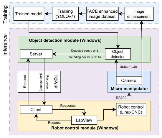
Figure 1.
Architecture of the proposed micro-manipulation system.
The training of the object detector model includes the image enhancement module, which enhances images of the environment, to highlight the details from otherwise very homogeneous images. This enhanced data set is used for training the object detector.
The robot control module includes a client, connected to the server in the object detection module, a LabView control application and a LinuxCNC-based robot control sub-module. The control application receives the object coordinates via the client and sends them as control commands to the micro-robot via the robot control sub-module. The micro-robot can then act upon received coordinates to locate the object of interest. Captures of the success of the movement and new environment can be made with the camera mounted upon the micro-manipulator. The main functionalities are further described in the following subsections.
3.1. Image Enhancement
Image enhancement plays a vital role in improving the image quality of living cells acquired from the microscope by emphasizing key features, reducing secondary characteristics, enriching information, and enhancing details. Fuzzy Automatic Contrast Enhancement (FACE) [5] is applied as a contrast enhancement technique for microscopic images of living cells. FACE changes the original pixel distribution to a less congested one while maintaining smoothness in the color distribution to prevent artifacts in living cell images. This approach utilizes a universal contrast enhancement variable (UCEV) to achieve better contrast enhancement automatically, without manually feeding parameters. The FACE technique utilizes a Fuzzy C-Means (FCM) method to classify pixels with similar colors together using clustering. The maximization of image entropy was automatically achieved through the use of UCEV. By utilizing FCM and UCEV, the image contrast was enhanced with good accuracy, without any artifacts or noise. The schematic diagram for FACE image enhancement is illustrated in Figure 2.

Figure 2.
FACE enhancement process.
In this method, it is assumed that there is an ‘n’ set of image pixels for . These image pixels are arranged into k groups, whose centers are described by . The presence of a ith pixel in jth cluster is indicated by . When using K-means as an exact clustering method [45,46], the value of can be either 0 or 1, where 0 represents inclusion and 1 represents exclusion. In contrast, FCM permits the representation of partial pixel inclusion within each cluster. According to FCM, will be a real number within a certain range of values from . The definition of total in-group variance is shown in Equation (1).
The inclusion parameters suggested by different studies can range from 1 to 5. For this method, it is considered to be 5. To achieve optimal image segmentation, it is crucial to minimize the inclusion of J pixels, as this reduces in-group variations, leading to larger ones. We can formulate the Lagrangian Equation stated in Equation (2), where represents a Lagrangian multiplier determined by the minimization problem L.
After solving the above equation to obtain the optimal fuzzy inclusiveness, the ideal parameter can be obtained as shown by Equations (3) and (4).
Equation (3) defines the center of the jth cluster, based on provided inclusiveness values, while Equation (4) determines the inclusiveness parameter based on the given cluster center points. The convergence of the value L persists as the parameterized process continues. In our approach, the parameterized technique is initiated with arbitrary assumptions denoted as , and this approach consistently yields reliable results across multiple trials. It is noteworthy that the FCM typically delivers the most accurate identification outcomes when operating within the CIELAB color space, established by the Commission International d’Eclairage, where L signifies lightness, and AB represents the dimensions of color components.
3.2. Entropy Maximization concerning the UCEV
The UCEV is a key concept in contrast enhancement. It acts as a dynamic control parameter that adjusts pixel values in images to enhance contrast and improve visual perception. UCEV adaptively broadens or narrows pixel value distributions, intensifying the contrast between features and addressing issues like overly bright regions. This approach dynamically manipulates pixel distributions while preserving image integrity, offering adaptability across different image types. UCEV’s automated approach eliminates the need for manual parameter adjustments, optimizing image quality by balancing contrast enhancement and image detail preservation through entropy maximization. This results in improved visual interpretation and image quality. The relationship of the UCEV adaptive mechanism influencing every new pixel and harmonizing the pixel colors is expressed by Equation (5).
where symbolizes the step size used in a line search that diverges from central cluster points through a fusion of fuzzy directions. A positive value of increases image dispersion, enhancing contrast, while a negative contracts pixel dispersion, potentially improving overly bright pictures. In the final contrast enhancement step, Equation (6) maximizes the global measurement, entropy J.
where p represents probability density, and is a set of image pixels obtained from Equation (5). This measurement assesses the unpredictability of pixel distribution. The analysis employs a grid set for computing image entropy. A higher entropy value signifies greater randomness in pixel distribution, indicating significant pixel variance. This optimization process, as expressed in Equation (6), leads to an improved image contrast. An illustration of the proposed FACE image enhancement method is depicted in Figure 3.
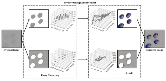
Figure 3.
Image enhancement process of proposed FACE method.
3.3. Visual Recognition
Individual living cell image recognition and localization is determined by finding the outline and coordinates of a cell. A state-of-the-art deep learning algorithm YOLOv7 [6] is used, which performs the real-time process of recognition and localization of cell contours and centers. Its architecture, as illustrated in Figure 4, consists of a backbone network, neck network, and head network. The backbone network extracts features from the input image, while the neck and head networks refine the feature maps to generate object recognition of living cells. The algorithm utilizes anchor-based object detection, where anchors are predefined bounding boxes of various sizes and shapes. This enables the network to detect living cells of different shapes and sizes accurately. YOLOv7 also uses a feature pyramid network (FPN) that extracts multi-scale features from the input image. The FPN combines feature maps of different resolutions to generate a feature pyramid, which enables the network to detect living cells at different scales. The network detects living cells in two stages using anchor boxes and the predicted objectness score. YOLOv7 learns to predict the bounding boxes and class labels of living cells from ground truth annotations during training, making it highly advanced and efficient for detecting living cells.
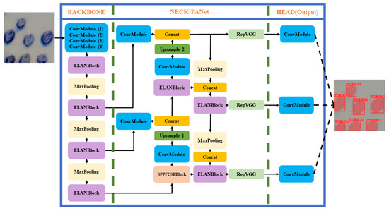
Figure 4.
Yolov7 architecture.
Utilizing the Contrast Enhancement (FACE) method for image enhancement notably elevates the quality of microscopic images by focusing on contrast improvement. When employed on microscopic images, these enhancement techniques serve as a pivotal element in augmenting object detection accuracy, especially when utilizing YOLOv7. This results in a more resilient and trustworthy detection process. To enhance the precision and robustness of automated yeast cell detection, the system employs a dual dataset approach. One dataset comprises yeast cell images that have undergone contrast enhancement using the FACE method, while the other dataset consists of the original, unaltered cell images. These two datasets are simultaneously integrated into the YOLOv7 model. The FACE-enhanced dataset is utilized for model training, where these images are fed into the model’s architectural components, including the backbone, neck, and head, to generate the necessary output. This process also results in the acquisition of training weights and model information. Conversely, the original dataset is deployed for predictive purposes. Leveraging the unaltered dataset reduces prediction time, as there is no need for contrast enhancement. This approach enables real-time detection of yeast cell contours and precise positioning. The complete process of the FACE–YOLO detection mechanism is illustrated in Figure 5.
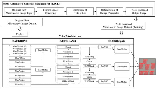
Figure 5.
FACE–YOLO hybrid enhancement detection model.
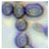
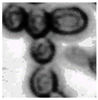
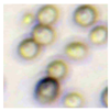
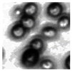
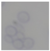
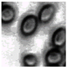
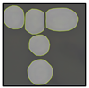
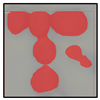
Initially, the original yeast cell images undergo enhancement using the FACE image enhancement method to improve the clarity of cell contours, making them more suitable for recognition. Subsequently, YOLOv7 is employed for training on these enhanced yeast cell images. Following the training process, the original yeast cell images are fed into the model, which produces images containing YOLO-detected results. The post-processed images obtained from YOLO detection are used to create masks for each cell, and individual cells are then extracted. Through binary processing, OpenCV is employed to identify the contours and centroids of the cells. Finally, these contours and centroids are superimposed onto the original images, displaying the contours and centroids of all yeast cells in the images, thereby facilitating subsequent cell manipulation with a gripper. The complete step-by-step image transformation and cell detection process is illustrated in Figure 6.
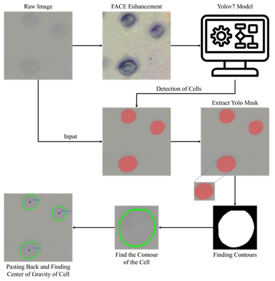
Figure 6.
Steps of cell detection and image transformation using the FACE–YOLO model.
3.4. Micro-Manipulator
An original four-axis micro-robot with scanning electrochemical microscope capabilities is developed and used for experiments. It consists of mechanical manipulation and optical systems, a motion controller and a main control unit. The main controller, implemented on a PC, controls the system, runs the user interface, and generates robot movement trajectories and measurements (Figure 7). Lower-level controllers and devices handle specific tasks. Driver control is realized using LinuxCNC V. 2.8.4 software, enabling compensation of backslashes and synchronized motion of all drives, which is required for tool manipulation in complex trajectories. The mechanical system of the microscope has four degrees of freedom, based on the kinematic scheme of an orthogonal manipulator with an additional Z-axis to separate tool movement from optical camera movement. The micro-manipulator housing, made of cast iron, provides thermal stability and high stiffness. Precisely controlled drives are installed for high accuracy and resolution. All implemented drives use a micrometric accuracy ball-screw motion translation mechanism controlled by stepper motors operating in 1/256 micro-step mode. The system consists of X-Y axes for table movement, one Z-axis for focal distance control, and another Z-axis for electrode, sensor, or micro-manipulation tool movement.
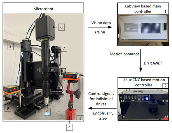
Figure 7.
Micro-positioning system. 1—PC; 2—micro computer (motion controller); 3—antivibration table; 4—laser distance sensors LAT 61 K 30/8 IUPN; 5—objective; 6—camera; 7—micro-manipulation tool drive; 8—camera drive; 9—stage with X and Y drives.
The X and Y axes are controlled by an 8MTF-102LS05 (Standa, Vilnius, Lithuania) drive. It is a two-axis, mutually perpendicular drive with a housing for universal mounting. Each axis has a travel of at least 102 mm and the carriages are mounted on rolling bearings. The displacement control has a resolution of at least 2.5 m and a maximum speed of at least 10 mm/s. The Z-axis, used for focal distance control, is driven by 8MT30-50 (Standa, Vilnius, Lithuania) drive. It has a displacement control resolution of at least 0.2 m, and a maximum speed of at least 2 mm/s. The Z-axis for a micro-manipulation tool movement is driven by the 8MT175-100 (Standa, Vilnius Lithuania) drive, with displacement control resolution of at least 0.31 m and a maximum speed of at least 10 mm/s. The micro-manipulation system is mounted on a pneumatic vibration isolation workstation 1VIS10W-075-09-77 (Standa, Vilnius, Lithuania) with a protective armrest, which guards the table from any outside impact.
4. Tests and Results
For developing a highly capable micro-manipulation system, a critical task at hand involves the systematic testing and validation of each constituent element. The effectiveness of the entire system depends on the precise functionality exhibited by its individual components. A focal point of this article revolves around the rigorous verification and testing procedures applied to the diverse modules constituting the micro-manipulation system. Each module undergoes an examination, first in isolation to gauge its intrinsic attributes and, subsequently, the functionality is validated as an integral part of the collective whole. The aim is to discern how these modules, when harmoniously orchestrated, perform in the specific context of examining yeast cells. This approach ensures that the system’s capabilities are not merely confined to individual prowess, but extend to a synergistic collaboration that addresses the unique challenges posed by yeast cell manipulation. A visualization of the complete setup can be seen in Figure 8.
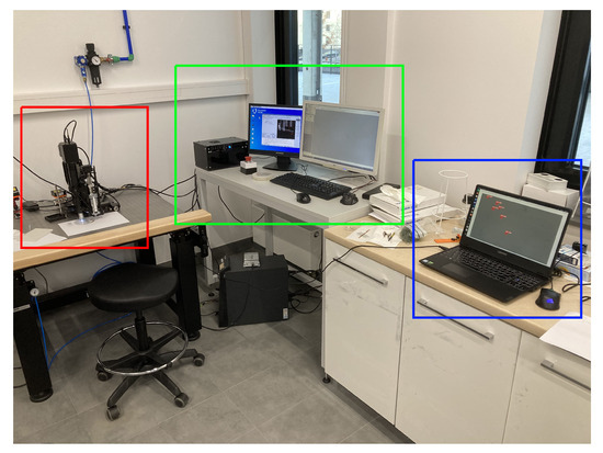
Figure 8.
Full experimental setup, outlined with red—micro-manipulator; green—micro-manipulator control; blue—object detection.
4.1. Image Enhancement
This study specifically addresses the assessment of fuzzy clustering performance in the context of yeast cell microscopic images. The dataset comprises 1000 raw images generated utilizing a camera equipped with the SONY IMX334 (Sony, Minato, Tokyo, Japan) sensor, which has a size of 1/1.8”, 2.0 × 2.0 m pixel size and a maximum resolution of 3840 × 2160, which was set to 1920 × 1080 during testing. This camera was coupled with a 14X–90X optical zoom achromatic field objective, seamlessly integrated into a custom positioning system. Post-capture, a detailed post-processing routine, including resizing to 500 × 500 pixels, was applied. For a comprehensive analysis, five distinct images were selected from the database, and three different techniques, such as Fuzzy Automatic Contrast Enhancement (FACE), Single Scale Retinex (SSR), and Histogram Equalization (HE) were applied. The outcomes of the contrast enhancement applied to each image, employing the designated FACE, SSR, and HE methods, are meticulously detailed in Table 1. Furthermore, to facilitate a comprehensive accuracy comparison, Table 1 also shows the 10-fold accuracy.

Table 1.
Image enhancement comparison results.
4.2. Image Recognition
As a visual recognition tool, YOLOv7 was utilized to detect yeast cells and their coordinates for images received from a camera, installed in the micro-manipulation system. This study involved creating two training datasets containing yeast cell image patterns to assess the impact of image enhancement on YOLOv7 object detection. The first model utilized the training dataset with original raw yeast cell images, while the second model used the training dataset with images enhanced by FACE. This dual dataset, encompassing both original raw images and their FACE-enhanced counterparts, formed the basis for the subsequent development and validation of the YOLOv7 cell detection model. The 10-fold accuracy comparison between the FACE-enhanced training dataset and the dataset without enhancement for the two YOLOv7 cell detection models, as depicted in Table 2, demonstrates that the FACE model yields favorable results. It achieves higher accuracy in yeast cell detection, even with original raw input images featuring low-contrast features.
Table 2.
10-fold accuracy comparison for with and without enhanced image.
To conduct a comprehensive evaluation of various object detection models and assess the congruence of their recognition outcomes with subsequent image processing, three distinct models were engaged—Mask R-CNN, YOLOv5, and YOLOv7—while maintaining a uniform label numbering system with a designated detection label number of 5. The findings from this comparative analysis unveiled that Mask R-CNN successfully identified three cells, YOLOv5 detected two cells and, impressively, YOLOv7 exhibited exemplary performance by accurately recognizing all five cells in the image. It is noteworthy that the superior accuracy demonstrated by YOLOv7, showcasing its ability to make highly precise predictions for each cell, outperformed the other models tested. A detailed breakdown of these comparative results is presented in Table 3.
Table 3.
Comparison of different object detection models.
Table 4 shows the accuracy results for the Mask R-CNN, YOLOv5, and YOLOv7 models based on 10-fold accuracy analysis. It is clear from Table 4 that YOLOv7 performs better than both Mask R-CNN and YOLOv5 in terms of overall accuracy.
Table 4.
10-fold accuracy comparison.
4.3. Micro-Manipulation Precision
Experimental measurements of the micro-robot were carried out to verify its accuracy. The measurements were made for each axis separately, according to a measurement methodology based on the ISO 230-2 [47] standard. The experimental accuracy measurements were carried out using the Laser Distance Sensor LAT 61 K 30/8 IUPN (Di-soric GmbH. & Co, Urbach, Germany). The obtained results showed that the value of the kinematic error decreases as the actuator warms up and that the influence on the actuator’s travel is not clearly defined. The results of the accuracy measures are presented in Table 5.
Table 5.
Micro-manipulator test results.
The average error in the Y-axis is influenced by the amount of forward travel, which is influenced by the accumulated pitch error and is proportional to the measured travel of the gear. The average errors of the X and Y axes have the same characteristics.
Roll friction is more influenced by small travel errors, whereas large travel errors have the effects of accumulated pitch errors. Research of the micro-manipulator’s positioning errors has shown that the errors in the actuators do not exceed the threshold for correct positioning of the tool concerning the test cell and the accuracy of the micro-manipulator is sufficient to achieve the desired goals.
4.4. Overall System
The combined system was tested to prove the feasibility of the concept, so practically no fine-tuning was performed for improved precision. It was set up and tested according to the inference module in the architecture shown in Figure 1. The micro-manipulation system, already described in Section 3.4, was combined with a separate computer running the object detection. It was running on Ubuntu Linux 22.04 with an Intel i7 12 core 2.60 GHz CPU and 16 GB of RAM.
To bridge the gap between camera and robot coordinates, a micro-scale grid with known grid size was used, visible in Figure 9 [48]. With a known mapping from the camera to the robot, the detected object coordinates could be transformed into movements for the robot. In our approach, the center of the camera’s vision was set as the goal for movement. After moving the micro-manipulator, the center of the cell of interest should coincide with the goal. The sample size does not permit a situation where the microscope is placed with the whole sample in the FOV, so a single home pose, from which the whole workspace could be seen, is not viable. For this reason, it was chosen to send relative movement coordinates to the manipulator. Whenever a cell was chosen for inspection, the system would transform the center of the detected cell as an X and Y distance for the micro-manipulator to move, relative to its current position. An example of moving to a detected cell can be seen in Figure 10.
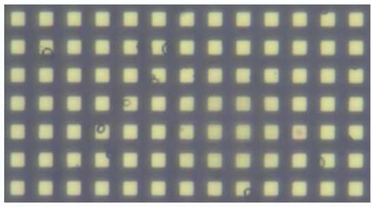
Figure 9.
Micro-scale grid used for calibrating.
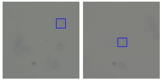
Figure 10.
Example of moving the micro-manipulator to a detected cell. Light blue—center of vision; green and dark blue—center and bounding box of chosen cell.
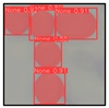
No specific description for choosing the cell to inspect was posed, which means that they could vary in sizes significantly. Five cell center movements, of which all cells were certainly similar sizes, around 3 m, can be seen visualized in Figure 11. These examples show an average offset of 0.5862 m, which is deemed precise enough to allow the tool to land in the area of the cell for further inspection or manipulation.
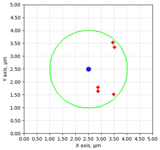
Figure 11.
Movement comparisons. Represented with blue—center of vision; red—cell movement endpoints; green—average size (3 m) of a yeast cell.
5. Discussion
5.1. Image Enhancement
The adoption of Fuzzy Automatic Contrast Enhancement (FACE) as an image enhancement technique in this study has demonstrated remarkable effectiveness in refining microscopic images of yeast cells. FACE, incorporating fuzzy clustering and optimizing entropy through a UCEV, autonomously improves image quality without the need for human-defined parameters. This automated enhancement yields a more refined pixel distribution, significantly enhancing image contrast while avoiding common issues such as color changes and visual artifacts. Comparative analyses underscore FACE’s superiority in terms of enhancement quality compared to other methods.
5.2. Visual Recognition
Moving forward, the application of YOLOv7 for yeast cell recognition in original microscopic images is a pivotal aspect of our investigation. Developing two distinct models using separate training datasets of yeast cell image patterns, we sought to explore the impact of image enhancement on YOLOv7 object detection. The initial model, trained with the original raw yeast cell image dataset, struggling to identify numerous small or blurred cells, revealed its limitations. In contrast, the second model, utilizing the dataset enhanced by FACE, showcased a significant improvement in visual quality and a substantial enhancement in object detection accuracy. This comparative analysis consistently highlights the superior performance of the FACE model, achieving higher accuracy in yeast cell detection with original raw images.
5.3. Micro-Manipulator
The developed micro-manipulator stands out as a precision instrument with notable experimental accuracy, showcasing its potential for biomedical applications. Its kinematic error reduction over time, influenced by warming up, underscores the need for optimal operating conditions. The micro-manipulator’s performance in adhering to ISO standards and maintaining accuracy within desirable ranges positions it as a reliable tool for intricate movements at the micrometer-size scale. In future micro-manipulator development, emphasis will be placed on compensating for accumulated errors through machine learning technology. A correlation exists between the number of move commands, their distances, and accelerations, facilitating the generation of an accurate error map for positioning error compensation. While the dynamic features of the micro-manipulator will remain unchanged for the existing structure, considerations will be given to the control of motors, path generation, and reactions to applied workload. Additional issues for manipulator improvement lie in the feedback reaction enhancement, therefore some additional sensors are planned to be installed. Such improvement will require establishing sensor data fusion in the new artificial intelligence hub within the existing controller.
5.4. Overall System
The whole system was successfully tested as a combination of multiple modules, with little to no manual labor involved, suggesting that such a system, when optimized, could duly improve working with living cells, especially in the form of automating precision-requiring processes, otherwise performed by hand. The tests also made it clear that some key factors were not amply addressed in this research; for example, the manipulator-camera calibration, which can be named as one of the main pillars on which the system functionality precision is based upon.
Another important aspect is the test sample itself. To be able to manipulate a cell after detection, it would need to be in an open sample, but as such a sample is no longer a flat surface, it raises the issue of getting the cells into focus. For the purpose of this research, the sample was kept under a cover glass, but this is one of the main points future research in this field should address.
6. Conclusions
The developed system, combining image enhancement, visual recognition, and a precision micro-manipulator, presents a promising direction for advancing microbiological research. The success of Fuzzy Automatic Contrast Enhancement (FACE) in refining microscopic images, coupled with YOLOv7’s efficacy in yeast cell detection, forms a robust foundation for automated and accurate analyses. The micro-manipulator’s high precision, validated through experimental measurements, positions it as a reliable tool for intricate movements at the micro-scale.
The integration of these components into a cohesive system demonstrates feasibility and potential in automating complex microbiological processes. Successful testing showcases the system’s adaptability in autonomously moving the micro-manipulator to detected cells, contributing to streamlined laboratory workflows. While manipulator-camera calibration remains an area for refinement, the system’s overall performance presents a significant stride towards efficient and precise microbiological experimentation.
As we look to the future, addressing calibration intricacies and challenges associated with open sample examinations will be paramount. Further refinements in automated cell selection criteria and the integration of additional functionalities can enhance the system’s versatility. Ultimately, this research lays the groundwork for transformative advancements in microbiological automation, fostering innovation in laboratory practices and contributing to the broader landscape of biomedical research.
Author Contributions
Conceptualization, J.A. and O.V.; methodology, J.A., O.V. and A.D.; validation, O.V., J.S.-Ž. and B.P.; formal analysis, O.V., J.A., J.S.-Ž. and B.P.; investigation, O.V., J.A., J.S.-Ž., B.P. and A.D.; resources, J.A., J.S.-Ž. and B.P.; data curation, J.A., O.V., J.S.-Ž., W.-C.T. and B.P.; writing—original draft preparation, J.A., O.V., J.S.-Ž., B.P. and W.-C.T.; writing—review and editing, J.A. and O.V.; visualization, J.A., O.V., J.S.-Ž., W.-C.T. and B.P.; supervision, J.A., M.G., V.B. and P.-T.L.; project administration, M.G., V.B. and P.-T.L.; funding acquisition, M.G., J.A., V.B. and P.-T.L. All authors have read and agreed to the published version of the manuscript.
Funding
This research has received financial support from the Research Council of Lithuania (LMTLT), No. P-LLT-21-6, Latvian Council of Science, Nr. LV-LT-TW/2023/9, and Ministry of Science and Technology (MOST) of Taiwan, No. MOST 110-2923-E-011-006-MY3. The financial support from Intelligent Manufacturing Innovation Center (IMIC) at National Taiwan University of Science and Technology (NTUST), Taiwan, which is a Featured Areas Research Center in Higher Education Sprout Project of Ministry of Education (MOE), Taiwan (since 2018) was appreciated.
Institutional Review Board Statement
Not applicable.
Data Availability Statement
The data presented in this study are available on request from the corresponding author. The data are not publicly available due to privacy.
Conflicts of Interest
The authors declare no conflict of interest. The funders had no role in the design of the study; in the collection, analyses, or interpretation of data; in the writing of the manuscript, or in the decision to publish the results.
References
- Safari, A.; Akdoğan, E.K. Piezoelectric and Acoustic Materials for Transducer Applications; Springer Science & Business Media: Berlin/Heidelberg, Germany, 2008. [Google Scholar]
- Yin, P.; Li, R.; Wang, Z.; Lin, S.; Tian, T.; Zhang, L.; Wu, L.; Zhao, J.; Duan, C.; Huang, P.; et al. Manipulation of a Micro-Object Using Topological Hydrodynamic Tweezers. Phys. Rev. Appl. 2019, 12, 044017. [Google Scholar] [CrossRef]
- Kumar, P. Development and Analysis of a Path Planner for Dexterous In-Hand Manipulation of Micro-Objects in 3D. Ph.D. Thesis, Université Bourgogne Franche-Comté, Dahmouche, Besançon, France, 2021. [Google Scholar]
- Zhang, D.; Ren, Y.; Barbot, A.; Seichepine, F.; Lo, B.; Ma, Z.C.; Yang, G.Z. Fabrication and optical manipulation of micro-robots for biomedical applications. Matter 2022, 5, 3135–3160. [Google Scholar] [CrossRef]
- Lin, P.T.; Lin, B.R. Fuzzy automatic contrast enhancement based on fuzzy C-means clustering in CIELAB color space. In Proceedings of the 2016 12th IEEE/ASME International Conference on Mechatronic and Embedded Systems and Applications (MESA), Auckland, New Zealand, 29–31 August 2016; pp. 1–10. [Google Scholar] [CrossRef]
- Wang, C.Y.; Bochkovskiy, A.; Liao, H.Y.M. YOLOv7: Trainable bag-of-freebies sets new state-of-the-art for real-time object detectors. In Proceedings of the IEEE/CVF Conference on Computer Vision and Pattern Recognition, Vancouver, BC, Canada, 17–24 June 2023; pp. 7464–7475. [Google Scholar]
- Riegel, L.; Hao, G.; Renaud, P. Vision-based micro-manipulations in simulation. Microsyst. Technol. 2021, 27, 3183–3191. [Google Scholar] [CrossRef]
- Chen, X.; Shi, Q.; Shimoda, S.; Sun, T.; Wang, H.; Huang, Q.; Fukuda, T. Micro Robotic Manipulation System for the Force Stimulation of Muscle Fiber-like Cell Structure. In Proceedings of the 2021 IEEE International Conference on Robotics and Automation (ICRA), Xi’an, China, 30 May–5 June 2021; IEEE: Piscataway, NJ, USA, 2021; pp. 7249–7254. [Google Scholar]
- Qin, F.; Xu, D.; Zhang, D.; Pei, W.; Han, X.; Yu, S. Automated Hooking of Biomedical Microelectrode Guided by Intelligent Microscopic Vision. IEEE/ASME Trans. Mechatron. 2023, 28, 2786–2798. [Google Scholar] [CrossRef]
- Zhang, Y.; Guo, X.; Wang, Q.; Wang, F.; Liu, C.; Zhou, M.; Ying, Y. Automated Dissection of Intact Single Cell From Tissue Using Robotic Micromanipulation System. IEEE Robot. Autom. Lett. 2023, 8, 4705–4712. [Google Scholar] [CrossRef]
- Zhou, A.; Zhang, Y. Intelligent 3D-Printed Magnetic Micro Soft Robotic Hand with Visual Feedback for Droplet Manipulation. In Proceedings of the 2023 WRC Symposium on Advanced Robotics and Automation (WRC SARA), Beijing, China, 19 August 2023; pp. 200–205. [Google Scholar] [CrossRef]
- Nguyen, X.H.; Mau, T.H.; Meyer, I.; Dang, B.L.; Pham, H.P. Improvements of Piezo-Actuated Stick–Slip Micro-Drives: Modeling and Driving Waveform. Coatings 2018, 8, 62. [Google Scholar] [CrossRef]
- Najar, F.; Choura, S.; El-Borgi, S.; Abdel-Rahman, E.M.; Nayfeh, A.H. Modeling and design of variable-geometry electrostatic microactuators. J. Micromech. Microeng. 2005, 15, 419–429. [Google Scholar] [CrossRef]
- Bejar, E.; Morán, A. Deep reinforcement learning based neuro-control for a two-dimensional magnetic positioning system. In Proceedings of the 2018 4th International Conference on Control, Automation and Robotics (ICCAR), Auckland, New Zealand, 20–23 April 2018; pp. 268–273. [Google Scholar]
- Zhou, M.; Yu, Y.; Zhang, J.; Gao, W. Iterative Learning and Fractional Order PID Hybrid Control for a Piezoelectric Micro-Positioning Platform. IEEE Access 2020, 8, 144654–144664. [Google Scholar] [CrossRef]
- Jie, X.; Kailin, Q.; Yuanhao, X.; Weixi, J. Method Combining Machine Vision and Machine Learning for Reed Positioning in Automatic Aerophone Manufacturing. In Proceedings of the 2019 4th International Conference on Robotics and Automation Engineering (ICRAE), Singapore, 22–24 November 2019; pp. 140–147. [Google Scholar]
- Leroux, M.; Raison, M.; Adadja, T.; Achiche, S. Combination of eyetracking and computer vision for robotics control. In Proceedings of the 2015 IEEE International Conference on Technologies for Practical Robot Applications (TePRA), Woburn, MA, USA, 11–12 May 2015; pp. 1–6. [Google Scholar]
- Kharin, A.Y. Deep learning for scanning electron microscopy: Synthetic data for the nanoparticles detection. Ultramicroscopy 2020, 219, 113125. [Google Scholar] [CrossRef]
- Nahrawi, N.; Mustafa, W.A.; Kanafiah, S.N.A.M.; Jamlos, M.A.; Khairunizam, W. Contrast enhancement approaches on medical microscopic images: A review. In Proceedings of the 11th National Technical Seminar on Unmanned System Technology 2019: NUSYS’19, Gambang, Malaysia, 2–3 December 2019; Springer: Singapore, 2021; pp. 715–726. [Google Scholar]
- Qi, Y.; Yang, Z.; Sun, W.; Lou, M.; Lian, J.; Zhao, W.; Deng, X.; Ma, Y. A comprehensive overview of image enhancement techniques. Arch. Comput. Methods Eng. 2022, 29, 583–607. [Google Scholar] [CrossRef]
- Dewey, B.E.; Zhao, C.; Reinhold, J.C.; Carass, A.; Fitzgerald, K.C.; Sotirchos, E.S.; Saidha, S.; Oh, J.; Pham, D.L.; Calabresi, P.A.; et al. DeepHarmony: A deep learning approach to contrast harmonization across scanner changes. Magn. Reson. Imaging 2019, 64, 160–170. [Google Scholar] [CrossRef]
- Zhang, Y.; Guo, X.; Ma, J.; Liu, W.; Zhang, J. Beyond brightening low-light images. Int. J. Comput. Vis. 2021, 129, 1013–1037. [Google Scholar] [CrossRef]
- Shirazi, S.H.; Umar, A.I.; Haq, N.U.; Naz, S.; Razzak, M.I. Accurate microscopic red blood cell image enhancement and segmentation. In Proceedings of the Bioinformatics and Biomedical Engineering: Third International Conference, IWBBIO 2015, Granada, Spain, 15–17 April 2015; Proceedings, Part I 3. Springer: Cham, Switzerland, 2015; pp. 183–192. [Google Scholar]
- Plissiti, M.E.; Nikou, C.; Charchanti, A. Accurate localization of cell nuclei in Pap smear images using gradient vector flow deformable models. In Proceedings of the International Conference on Bio-Inspired Systems and Signal Processing, Valencia, Spain, 20–23 January 2010; SciTePress: Setúbal, Portugal, 2010; Volume 2, pp. 284–289. [Google Scholar]
- Rejintal, A.; Aswini, N. Image processing based leukemia cancer cell detection. In Proceedings of the 2016 IEEE International Conference on Recent Trends in Electronics, Information & Communication Technology (RTEICT), Bangalore, India, 20–21 May 2016; IEEE: Piscataway, NJ, USA, 2016; pp. 471–474. [Google Scholar]
- Tyagi, M.; Saini, L.M.; Dahyia, N. Detection of poikilocyte cells in iron deficiency anaemia using artificial neural network. In Proceedings of the 2016 International Conference on Computation of Power, Energy Information and Communication (ICCPEIC), Melmaruvathur, India, 20–21 April 2016; IEEE: Piscataway, NJ, USA, 2016; pp. 108–112. [Google Scholar]
- Somasekar, J.; Reddy, B.E. Contrast-enhanced microscopic imaging of malaria parasites. In Proceedings of the 2014 IEEE International Conference on Computational Intelligence and Computing Research, Coimbatore, India, 18–20 December 2014; IEEE: Piscataway, NJ, USA, 2014; pp. 1–4. [Google Scholar]
- Sparavigna, A.C. Gimp Retinex for enhancing images from microscopes. Int. J. Sci. 2015, 4, 72–79. [Google Scholar] [CrossRef]
- Bhateja, V.; Yadav, A.; Singh, D.; Chauhan, B.K. Multi-scale Retinex with Chromacity Preservation (MSRCP)-Based Contrast Enhancement of Microscopy Images. In Proceedings of the Smart Intelligent Computing and Applications, Volume 2: Proceedings of Fifth International Conference on Smart Computing and Informatics (SCI 2021), Hyderabad, India, 17–18 September 2021; Springer: Singapore, 2022; pp. 313–321. [Google Scholar]
- Kotwal, S.; Rani, P.; Arif, T.; Manhas, J. Machine Learning and Deep Learning Based Hybrid Feature Extraction and Classification Model Using Digital Microscopic Bacterial Images. SN Comput. Sci. 2023, 4, 687. [Google Scholar] [CrossRef]
- Ronneberger, O.; Fischer, P.; Brox, T. U-net: Convolutional networks for biomedical image segmentation. In Proceedings of the Medical Image Computing and Computer-Assisted Intervention—MICCAI 2015: 18th International Conference, Munich, Germany, 5–9 October 2015; Proceedings, Part III 18. Springer: Cham, Switzerland, 2015; pp. 234–241. [Google Scholar]
- Hollandi, R.; Szkalisity, A.; Toth, T.; Tasnadi, E.; Molnar, C.; Mathe, B.; Grexa, I.; Molnar, J.; Balind, A.; Gorbe, M.; et al. nucleAIzer: A parameter-free deep learning framework for nucleus segmentation using image style transfer. Cell Syst. 2020, 10, 453–458. [Google Scholar] [CrossRef] [PubMed]
- Greenwald, N.F.; Miller, G.; Moen, E.; Kong, A.; Kagel, A.; Dougherty, T.; Fullaway, C.C.; McIntosh, B.J.; Leow, K.X.; Schwartz, M.S.; et al. Whole-cell segmentation of tissue images with human-level performance using large-scale data annotation and deep learning. Nat. Biotechnol. 2022, 40, 555–565. [Google Scholar] [CrossRef]
- Haberl, M.G.; Churas, C.; Tindall, L.; Boassa, D.; Phan, S.; Bushong, E.A.; Madany, M.; Akay, R.; Deerinck, T.J.; Peltier, S.T.; et al. CDeep3M—Plug-and-Play cloud-based deep learning for image segmentation. Nat. Methods 2018, 15, 677–680. [Google Scholar] [CrossRef] [PubMed]
- Lalit, M.; Tomancak, P.; Jug, F. Embedseg: Embedding-based instance segmentation for biomedical microscopy data. Med. Image Anal. 2022, 81, 102523. [Google Scholar] [CrossRef] [PubMed]
- Nitta, N.; Sugimura, T.; Isozaki, A.; Mikami, H.; Hiraki, K.; Sakuma, S.; Iino, T.; Arai, F.; Endo, T.; Fujiwaki, Y.; et al. Intelligent image-activated cell sorting. Cell 2018, 175, 266–276. [Google Scholar] [CrossRef] [PubMed]
- Fujita, S.; Han, X.H. Cell Detection and Segmentation in Microscopy Images with Improved Mask R-CNN. In Proceedings of the Asian Conference on Computer Vision, Kyoto, Japan, 30 November–4 December 2020; pp. 58–70. [Google Scholar]
- Whipp, J.; Dong, A. YOLO-based Deep Learning to Automated Bacterial Colony Counting. In Proceedings of the 2022 IEEE Eighth International Conference on Multimedia Big Data (BigMM), Naples, Italy, 5–7 December 2022; IEEE: Piscataway, NJ, USA, 2022; pp. 120–124. [Google Scholar]
- López Flórez, S.; González-Briones, A.; Hernández, G.; Ramos, C.; de la Prieta, F. Automatic Cell Counting with YOLOv5: A Fluorescence Microscopy Approach. Int. J. Interact. Multimed. Artif. Intell. 2023, 8. [Google Scholar] [CrossRef]
- Huang, Z.J.; Patel, B.; Lu, W.H.; Yang, T.Y.; Tung, W.C.; Bučinskas, V.; Greitans, M.; Wu, Y.W.; Lin, P.T. Yeast cell detection using fuzzy automatic contrast enhancement (FACE) and you only look once (YOLO). Sci. Rep. 2023, 13, 16222. [Google Scholar] [CrossRef] [PubMed]
- Yin, Z.; Bise, R.; Chen, M.; Kanade, T. Cell segmentation in microscopy imagery using a bag of local Bayesian classifiers. In Proceedings of the 2010 IEEE International Symposium on Biomedical Imaging: From Nano to Macro, Rotterdam, The Netherlands, 14–17 April 2010; pp. 125–128. [Google Scholar] [CrossRef]
- Lamberti, W.F. Blood cell classification using interpretable shape features: A Comparative study of SVM models and CNN-Based approaches. Comput. Methods Programs Biomed. Update 2021, 1, 100023. [Google Scholar] [CrossRef]
- Brehar, R.; Mitrea, D.A.; Vancea, F.; Marita, T.; Nedevschi, S.; Lupsor-Platon, M.; Rotaru, M.; Badea, R.I. Comparison of Deep-Learning and Conventional Machine-Learning Methods for the Automatic Recognition of the Hepatocellular Carcinoma Areas from Ultrasound Images. Sensors 2020, 20, 3085. [Google Scholar] [CrossRef] [PubMed]
- Lai, Y. A comparison of traditional machine learning and deep learning in image recognition. J. Phys. Conf. Ser. 2019, 1314, 012148. [Google Scholar] [CrossRef]
- Jain, A.K. Data clustering: 50 years beyond K-means. Pattern Recognit. Lett. 2010, 31, 651–666. [Google Scholar] [CrossRef]
- Wagstaff, K.; Cardie, C.; Rogers, S.; Schrödl, S. Constrained K-means Clustering with Background Knowledge. In Proceedings of the ICML, Williamstown, MA, USA, 28 June–1 July 2001; Volume 1, pp. 577–584. [Google Scholar]
- ISO 230-2:2014; Test Code for Machine Tools: Part 2: Determination of Accuracy and Repeatability of Positioning of Numerically Controlled Axes. International Organization for Standardization: Geneva, Switzerland, 2014. Available online: https://www.iso.org/standard/55295.html (accessed on 10 December 2023).
- Dzedzickis, A. Atominių Jėgų Mikroskopo Jutiklio Mechaninės Struktūros Modeliavimas ir Dinaminių Charakteristikų Tyrimas. Ph.D. Thesis, Vilnius Gediminas Technical University, Vilnius, Lithuania, 2019. Available online: http://dspace.vgtu.lt/handle/1/3784 (accessed on 10 December 2023).


Disclaimer/Publisher’s Note: The statements, opinions and data contained in all publications are solely those of the individual author(s) and contributor(s) and not of MDPI and/or the editor(s). MDPI and/or the editor(s) disclaim responsibility for any injury to people or property resulting from any ideas, methods, instructions or products referred to in the content. |
© 2023 by the authors. Licensee MDPI, Basel, Switzerland. This article is an open access article distributed under the terms and conditions of the Creative Commons Attribution (CC BY) license (https://creativecommons.org/licenses/by/4.0/).