Article

Effect of Solidified Depth on the Vertical Compressive Bearing Characteristics of the Soil Continuously Solidified Pile Group Foundation

1
School of Earth Science and Engineering, Shandong University of Science and Technology, Qingdao 266590, China
2
Qingdao Research Institute of Surveying and Mapping, Qingdao 266590, China
3
School of Environmental Science and Engineering, Ocean University of China, Qingdao 266100, China
*
Author to whom correspondence should be addressed.
Appl. Sci. 2023, 13(23), 12850; https://doi.org/10.3390/app132312850
Submission received: 25 October 2023 / Revised: 23 November 2023 / Accepted: 28 November 2023 / Published: 30 November 2023

Abstract

:
To meet the ultra-high bearing capacity design requirements of pile foundations under geological conditions without a good holding layer, we invented a new type of group pile foundation with the soil continuously solidified between piles (hereinafter referred to as the SCS group pile foundation). Considering the solidified depth as a key influencing factor, the vertical ultimate compressive bearing capacity, load transfer law, and damage pattern of the soil around the continuously solidified group pile foundation were investigated using an indoor half-model test. The results revealed that the setting of the continuously solidified part has a significant effect on its compressive bearing characteristics. The ultimate compressive bearing capacity of the SCS group pile foundation was increased by four to nine times compared with the traditional group pile foundation. When the pile spacing is 4–6D (D = pile diameter), designing a continuously solidified depth greater than 14D is recommended. Except for the solidified depths of 2D and 18D, the lateral resistances of the other model piles first increase and then decrease with increasing depth. The maximum values were located at the continuously solidified part and were obviously larger than those of the other pile sections. The maximum pile lateral frictional resistance was provided at the maximum depth of the continuously solidified part. After setting up the continuously solidified part, none of the bearing capacity of the pile ends exceeded 5%. The bearing capacity of the SCS group pile foundation was mainly shared by the continuously solidified part and the pile lateral frictional resistance. For the same pile spacing, the high strain damage zone of the soil at the bottom of the continuously solidified 2D–14D foundation was “abacus bead”; when the burial depth of the continuously solidified part reached 18D, the foundation soil exhibited “inverted bowl” damage.

1. Introduction

As a widely used deep foundation, the pile foundation can transfer loads from the superstructure through the pile body to the holding layer at depth. However, with the increasing height of the building (structure), the superstructure requires an increasingly larger bearing capacity and stricter deformation of the foundation. Scholars both domestic and abroad have obtained fruitful research results in improving the horizontal and vertical bearing capacity of piles through pile body design and soil solidification between piles.
Increasing the pile diameter (D), improving the pile strength, enhancing the pile cross-sectional shapes, and soil solidification between piles are all effective methods to improve the horizontal bearing capacity of the pile foundation. Traditional piles can be strengthened by changing the cross-sectional shape of the pile and using high-strength materials to reinforce the pile body [1,2,3,4,5]. It has been shown that the horizontal displacement of pile tops declines after the reinforcement of soil between the supporting piles; the supporting effect is better than that of ordinary row piles [6,7,8,9], and the damage mechanism of double-row piles under different widths of reinforcement zones is different [10].
Increasing the pile’s diameter and length, improving the cross-sectional shape of piles, and the solidification of soil between piles are common methods to improve the vertical bearing capacity of pile foundations. At present, the mature variable section pile techniques include expanded bottom piles and squeezed branch piles [11,12,13]; these piles gradually evolved and developed into extruded and expanded multi-disk piles, rotary expanded multi-disk piles, etc. [14,15,16,17]. Variable section piles mainly alter the cross-section of the pile body to increase the contact area between the pile body and the soil to improve the bearing capacity [18,19]. Grouting is a highly effective way of soil reinforcement [20]. During the grouting process, the slurry produces a series of physicochemical effects, such as cementation and compaction in the soil around the pile, ultimately forming a “cemented soil” at the tip of the pile. This improves the physical and mechanical properties of soil at the tip and around the pile, thus enlarging the bearing capacity of the pile foundation [21,22]. In the process of grouting, piles and soil between piles form a composite foundation [23] and produce an extrusion effect [24,25], the physical and mechanical properties of the composite foundation inter-pile soil have been greatly improved [26,27]. In addition, new techniques, such as biological grouting, have been increasingly applied to improve the strength of soil between piles [28].
In the case that a large diameter monopile cannot meet the loading and deformation requirements of the superstructure, the group pile is widely used due to its advantages of good integrity, small and uniform deformation and settlement, high bearing capacity, strong overturning resistance, and its ability to withstand large horizontal forces. However, the bearing discs of variable section group piles exhibit the problem of interacting with each other, resulting in a reduction in the group pile effect. To date, most relevant studies have focused on discontinuous solidified soil between piles.
In the alluvial plain area with a large thickness obtained during the Quaternary period, due to the absence of a good holding layer within several tens of meters, there is a bottleneck in the lateral resistance of the pile that can be compensated with the soil around the weak pile. The magnitude of improving the bearing capacity by increasing the diameter and length of piles, improving the cross-sectional shape of piles, and reinforcing the soil between the piles is limited, which makes it difficult to satisfy the design requirements of high-rise and super high-rise buildings for high bearing capacity pile foundations. Accordingly, Sun Tao et al. [29] invented a group pile foundation called soil continuously solidified (SCS group pile foundation) between the pile systems and presented its construction method. This technique can be applied using rotary spraying methods such as MJS [30] to set up a continuous “artificial holding layer” in the dominant stratum, such as a sand layer underneath the group pile foundation. This system mainly consists of two or more foundation piles, bearing platforms, a continuously solidified part, soil between piles in the target layer, and soil between piles in the non-target layer. Both precast piles and bored piles can be used for the SCS group pile foundation, but the splicing of precast piles should be emphasized [31]. The upper end of the foundation pile is embedded in the bearing platform to a certain length and fixedly connected with the bearing platform, while the rest of the pile is buried in the soil layer. The continuously solidified part is set in the soil between the piles in the target layer. The SCS group pile foundation system is shown in Figure 1. Sun Tao et al. invented the SCS group pile foundation system and presented its construction method. This new method adopts the foundation treatment technology to continuously strengthen the target layer, which changes the current design idea of improving the bearing capacity of the pile group by improving the single pile. After reinforcement, the soil between the piles of the target layer forms a continuous and high-strength whole in the horizontal direction, which provides a good artificial holding layer for the group piles. Studies have shown that the continuous solidification of soil between piles to improve the pile-bearing capacity is a cost-effective method [32]; however, as a brand new pile type, its bearing mechanism urgently needs to be further clarified. We proposed to investigate the vertical compressive bearing performance of the continuously solidified group pile foundation with soil between piles in the sandy soil foundation on the basis of a model test combined with the theoretical analysis and observation of the dynamic change process of the foundation. This is important for the design and application of the SCS group pile foundation.

2. Test Materials and Equipment

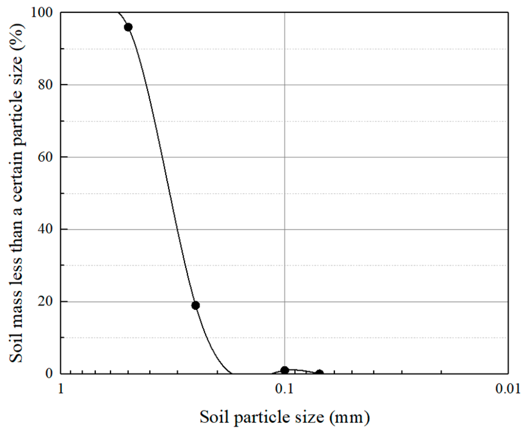
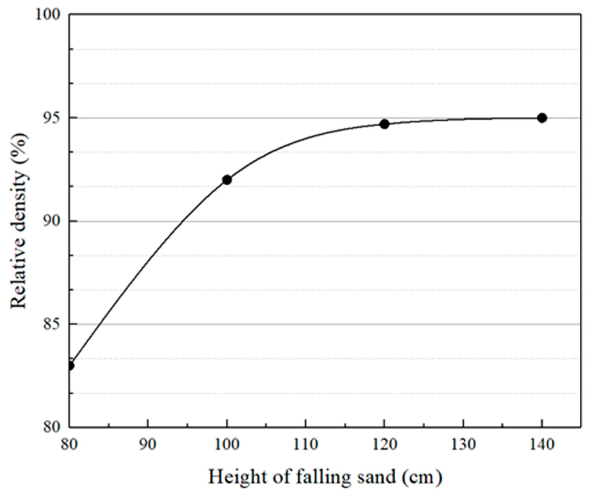
2.1. Foundation Material
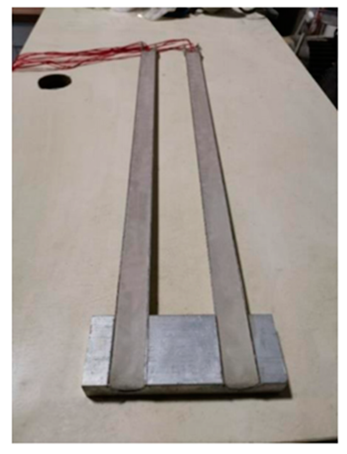
In this paper, white artificial quartz sand with grading within the interval of 0.1 mm~1 mm was selected for model foundation fabrication according to Sun Tao et al. [32]. The particle grading curve of foundation soil is depicted in Figure 2, and the basic physical and mechanical properties of quartz sand are listed in Table 1.
The ratio of the grain size of the sandy soil to the pile diameter of the model piles in this test was much lower than 1/20; thus, the influence produced by the model foundation on the pile-bearing capacity can be neglected [33,34].
In order to verify the relationship between the foundation compactness and the height of the sand drop, the sand drop test was set up for a height of 80 cm, 100 cm, 120 cm, and 140 cm for four groups of the drop experiments, where each group of drops were configured with three parallel samples. In the formal test, we used U-shaped paths for the sand drop, as shown in Figure 3.
As can be seen from Figure 3, the compactness of the model foundation increases with the increasing height of sand fall, and the growth rate slows down and stabilizes at about 0.95 when the fall distance is more than 120 cm. Considering the convenience of foundation fabrication, this test adopted the 120 cm sand fall height.

2.2. Pile Material

The indoor half model was used for this test [35]. The model piles were made of aluminum alloy tubes cut along the center of the longitudinal axis, with a length of 700 mm, an outer diameter (D) of 30 mm, an inner diameter of 27 mm, and a wall thickness of 1.5 mm. The piles were buried into the model foundation by 600 mm. The continuously solidified part was made of aluminum alloy with the same material as that of the model piles and also cut along the central axis of the longitudinal axis. The length of the continuously solidified part had a pile spacing of +60 mm + 40 mm, a width of 30 mm, and a height of 60 mm. At the same time, semi-circular cross-section holes of 30 mm diameter were cut in the continuously solidified part, and the base pile was tightly bonded to the continuously solidified part using structural adhesives. Strain gauges were pasted on the inside of the pile and filled with wax. To simulate the surface roughness of the pile body in the actual situation, threads with a depth of 0.5 mm and a spacing of 1 mm were machined on the outer surface of the pile body. The completed model pile is shown in Figure 4.

2.3. Test Equipment

The test was conducted using a MSZ-1 model test loading device, which contains a load cell, a displacement transducer, a data collector, and strain gauges [35].

3. Test Plan and Implementation

3.1. Protocol of Test

A total of 12 groups of indoor half-mold tests were designed, as shown in Figure 5. Among them, two groups of group pile foundations without continuous solidification were designated as the control group, as shown in Figure 5a. There were 10 groups of half-model tests with continuously solidified parts, and the pile spacings were 4D and 6D. Under the same pile diameter, different depths of the upper surface of the solidified part were tested, namely 2D, 6D, 10D, 14D, and 18D. To study the load transferring law of model piles under the action of vertical load, according to the test program, strain gauges were pasted on the corresponding position of each group of model piles, as shown in Figure 5b,c. The test program is shown in Figure 5b,c.

3.2. Test Implementation

First, the model pile was held in the model barrel using a holding device, and the surface of the pile was designed to closely fit the lower tempered glass to prevent the observation of foundation damage from being affected by sand leakage that could destroy the marker layer. Then, the sand rain method was used to prepare the model foundation. In this process, for every 2 cm of sand fall, it was necessary to use two kinds of dyeing sand (red and black) to lay the sign layer alternately in the range near the solidified part and scrape the sign layer without disturbing the foundation. As the foundations were being made, the pile-holding device was moved up with the foundation height for practicality. Finally, the MSZ-1 loading device, YHD-50 displacement gauge, and KYOWA EDX-10B compact data collector were installed. The loading device was set to a 0.5 mm/min strain loading mode, the collector collected data at 1 s intervals, and the end condition of the test was that the displacement reached 20 mm. During the test, the camera was used to record the whole process of dynamic changes in the foundation, and the deformation process of sandy soil foundations at different loading stages were clarified via time comparisons.

4. Results and Discussion

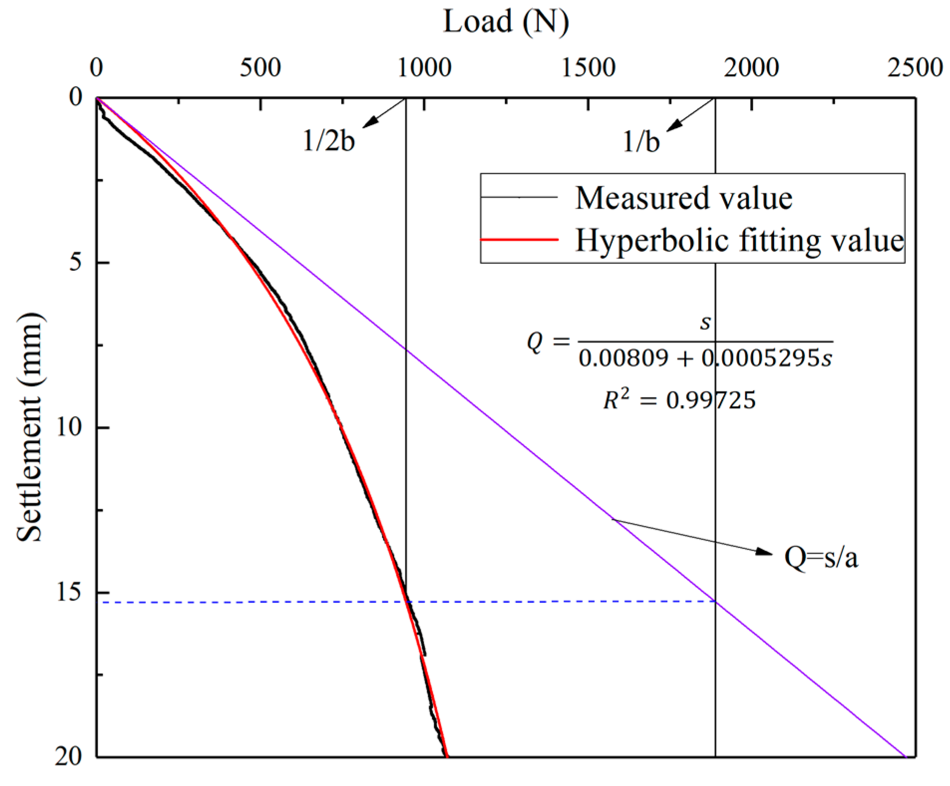
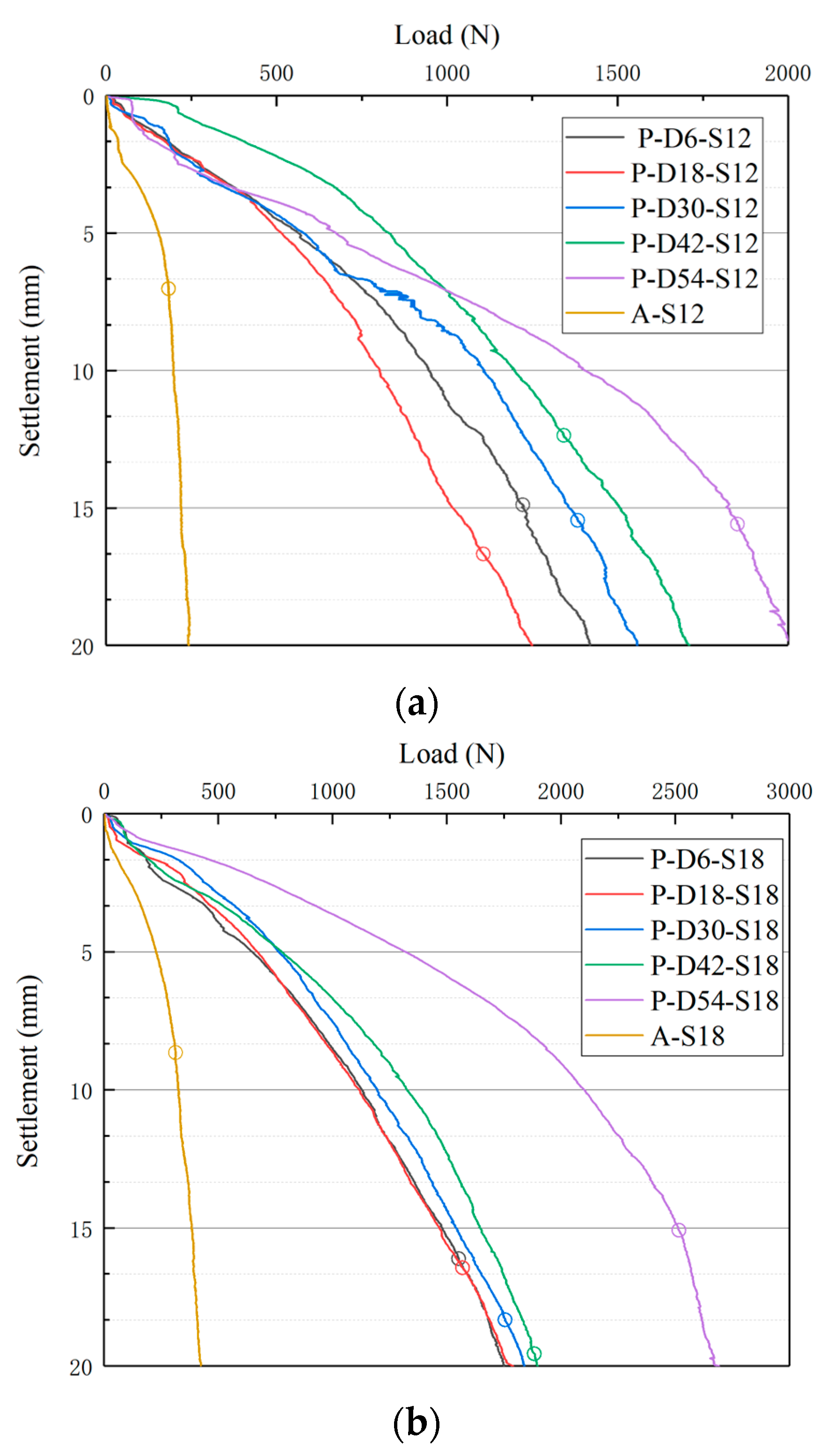
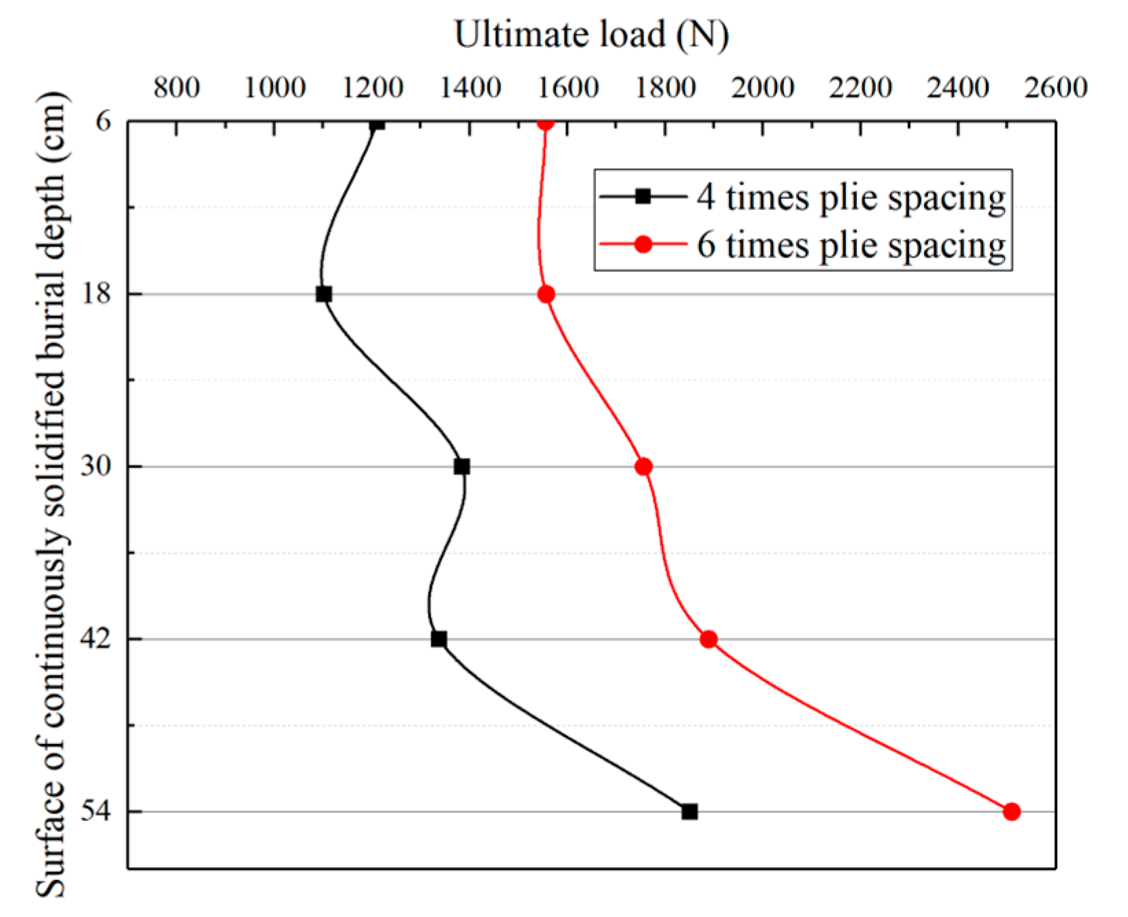
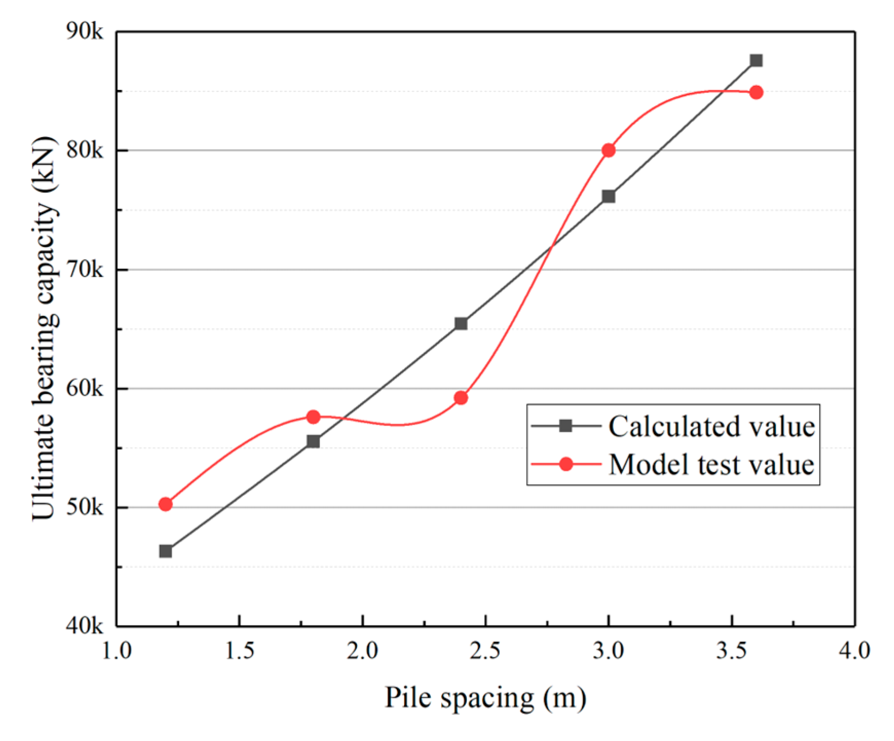
4.1. Ultimate Compressive Capacity

Figure 6 shows the load–settlement curves of double piles with 6D pile spacing without continuously solidified parts and with continuously solidified parts at 2D burial depth. From Figure 6, it can be seen that the bearing capacity of the SCS group pile foundation with a continuously solidified part is significantly improved.
Since the load–settlement curves of the SCS group pile foundation did not show peaks, this paper adopted the double-curve fitting method [34,35,36,37] to determine the ultimate bearing capacity of the piles. Figure 7 illustrates the process of determining the ultimate bearing capacity of model piles using this method.
The load–settlement curve was fitted as:
Q = s a + b s
where Q represents the pile top load value (unit: N), s represents the settlement value (unit: mm), and a and b represent the double-curve fitting parameters. After fitting, the ultimate bearing capacity of each group of model piles and the corresponding settlements were determined and shown in Table 2.
As shown in Table 2, the ultimate compressive bearing capacity of each group of SCS group pile foundation is increased by four to nine times compared with that of the traditional group pile foundations, and the settlement of the pile tops at the time of reaching the ultimate compressive bearing capacity is also increased by about once. Under the premise that the integrity of the pile body and the stiffness of the solidified can be guaranteed, the installation of the continuously solidified part can help to significantly improve the vertical bearing capacity of the group pile foundation.
In order to study the influence of a continuously solidified position on the bearing characteristics of the SCS group pile foundation, the load–settlement relationship of each group was plotted according to the test data. The numerical points of the ultimate bearing capacity of each group obtained using the hyperbolic method are highlighted and labeled in Figure 8.
The relationship between the ultimate bearing capacity of each group of SCS group pile foundations and solidified burial depths is shown in Figure 9. As illustrated in Figure 8 and Figure 9, the solidified burial depth affects the bearing capacity of the SCS group pile foundation. The model pile with a solidified upper surface burial depth of 6D had the lowest ultimate bearing capacity, followed by the model pile with a solidified upper surface burial depth of 2D. Except for the pile P-D42-S12, the ultimate bearing capacity increased with burial depth when the burial depth was greater than 6D. However, there was no significant change in the ultimate bearing capacity when the continuously solidified burial depth was increased from 10D to 14D. The maximum ultimate bearing capacity was reached at an 18D solidified burial depth, which is much larger than that of other model piles. Therefore, when the pile spacing is 4–6D, it is recommended that the design of continuously solidified burial depth is more than 14D.

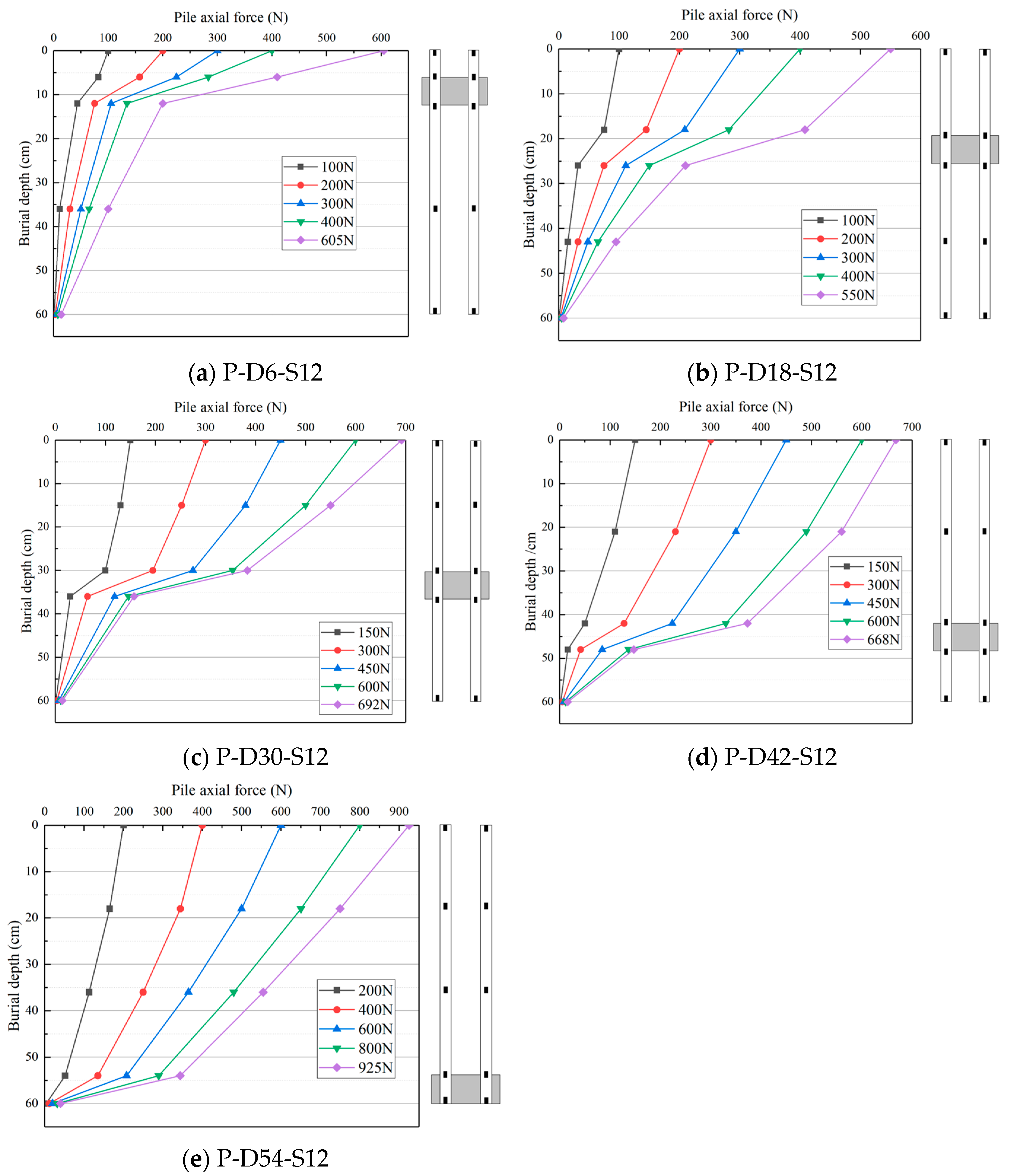
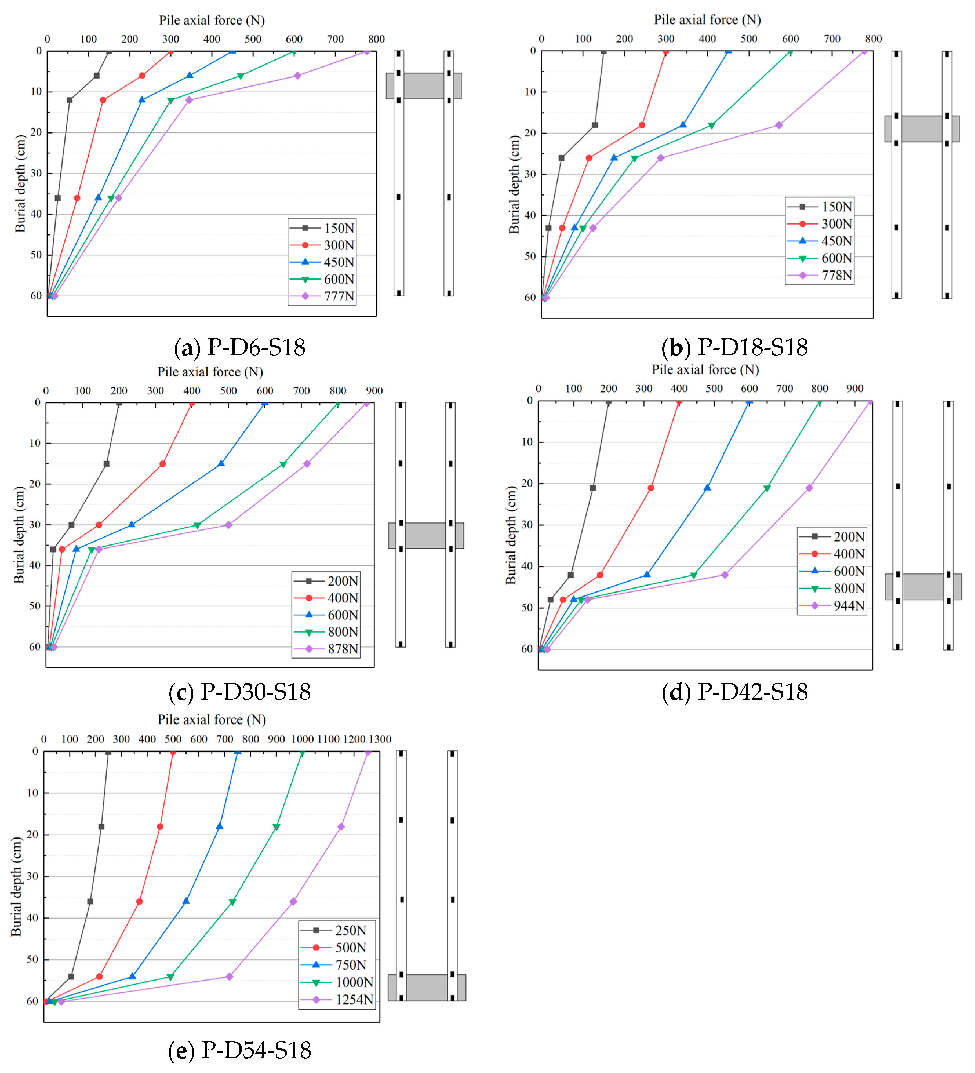
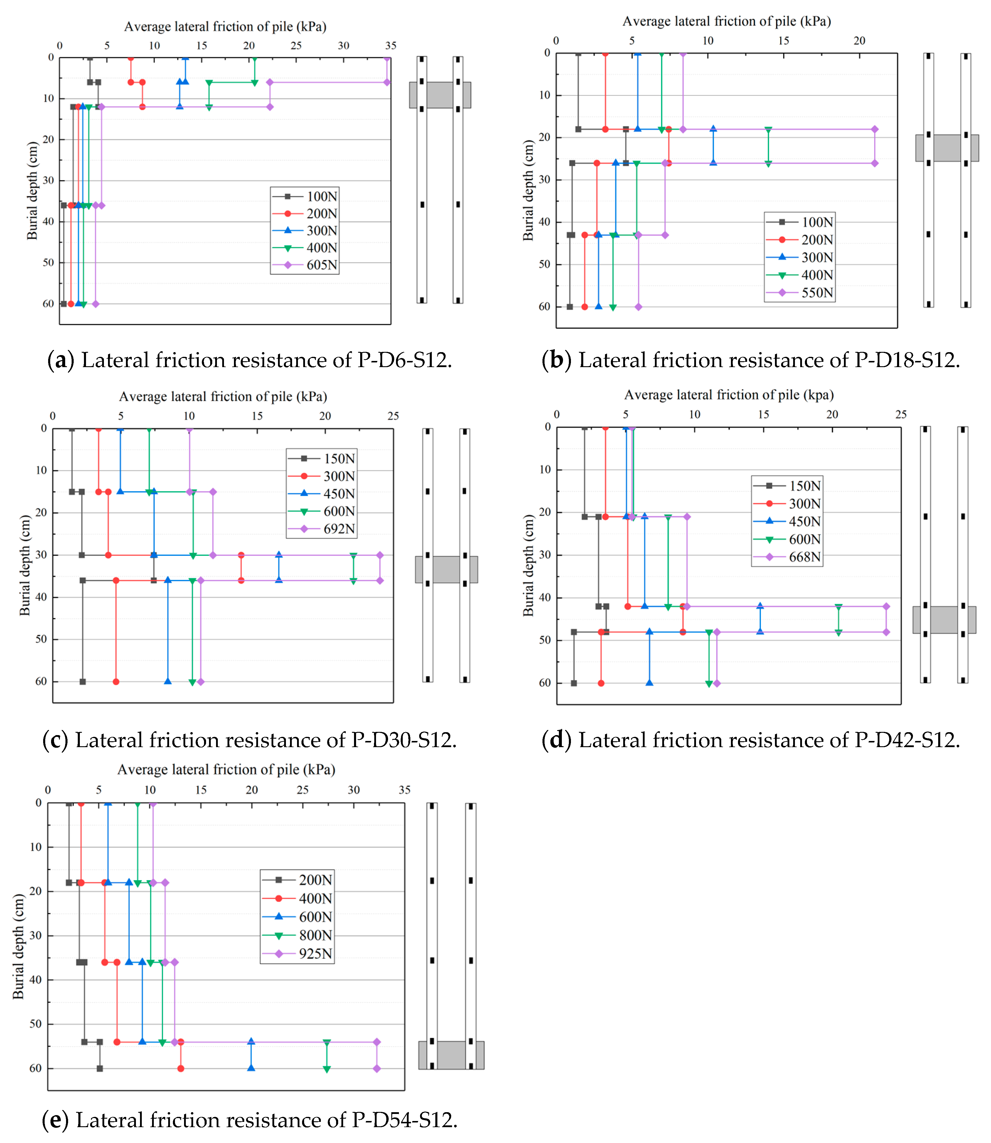
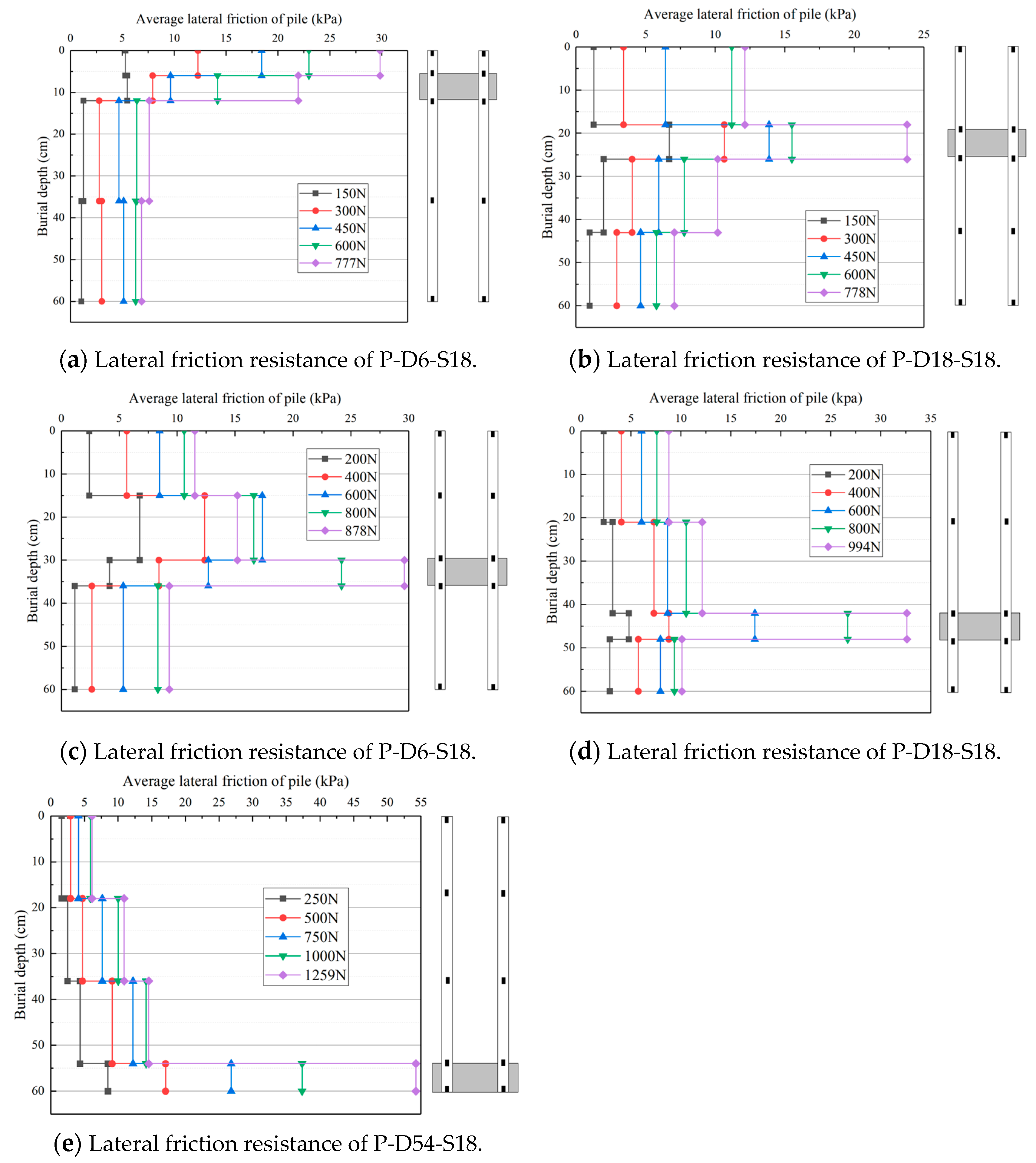
4.2. Pile Shaft Axial Force and Side Friction Resistance

The data obtained from the axial force test were used to plot the distribution curve of the axial force of each model pile along the depth of penetration, as shown in Figure 10 and Figure 11.
From the above axial force distribution curve, it can be found that the change rule of the axial force of each group of piles was basically the same. The axial force of the SCS group pile foundation at different buried depths increased with the increasing pile top load; the axial force of each model pile body gradually decreased with the increasing continuously solidified buried depths; the attenuation rate rose with the increasing load. These phenomena indicate that the pile lateral friction resistance is gradually exerted along the pile body from top to bottom, and at the same time, the pile lateral friction resistance is more and more fully exerted with the increasing relative pile–soil displacement. The installation of a continuously solidified part makes the pile body axial force significantly decrease at the top and bottom of the continuously solidified part, and the reduced axial force is all borne via the continuously solidified part and transferred to the soil.
It has been assumed that the lateral friction resistance of the pile body between two strain gauges is uniformly distributed along the pile body, and the average lateral friction resistance is calculated by dividing the pile body into several segments with different lengths using the affixed strain gauges with the formula shown below:
q s = N i N i + 1 A
where q s —average friction resistance (unit: kPa); N i —axial force at pile body i (unit: N); N i + 1 —axial force at i + 1 of the pile body (unit: N); and A—surface area of pile section side (unit: m 2 ). According to the above formula, the average lateral friction resistance of each model pile is calculated and the distribution curve along the buried depth is drawn, as shown in Figure 12.
As can be seen from Figure 12 and Figure 13, the setting of the continuously solidified part influences the distribution pattern of lateral resistance. The lateral resistance gradually decreases with depth at a 2D continuously solidified depth, while it gradually increases with depth at an 18D continuously solidified depth. The lateral resistance of other model piles first increases and then decreases with depth; the maximum value was located at the continuously solidified part and is obviously larger than that of other pile sections. The lateral resistance of different pile sections of the model pile show different degrees of increase with the increasing load. When the depth of the continuously solidified part reached its maximum value, the lateral resistive force provided by it also reached its maximum.

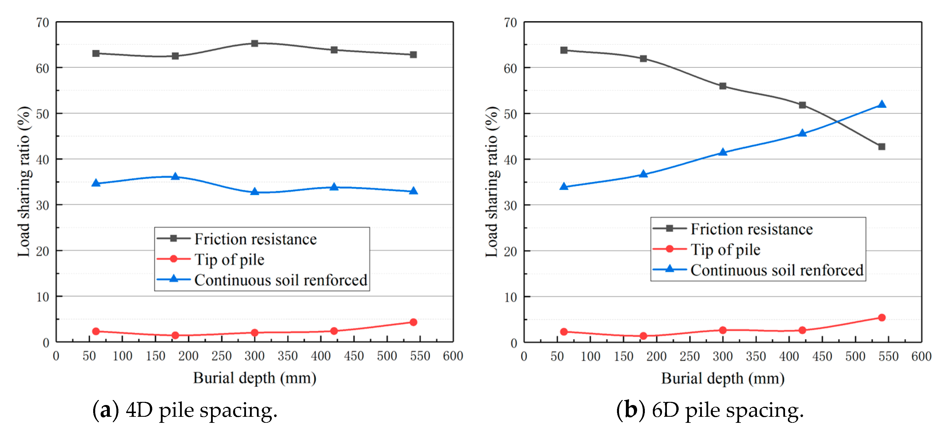
4.3. Pile Load-Sharing Ratio
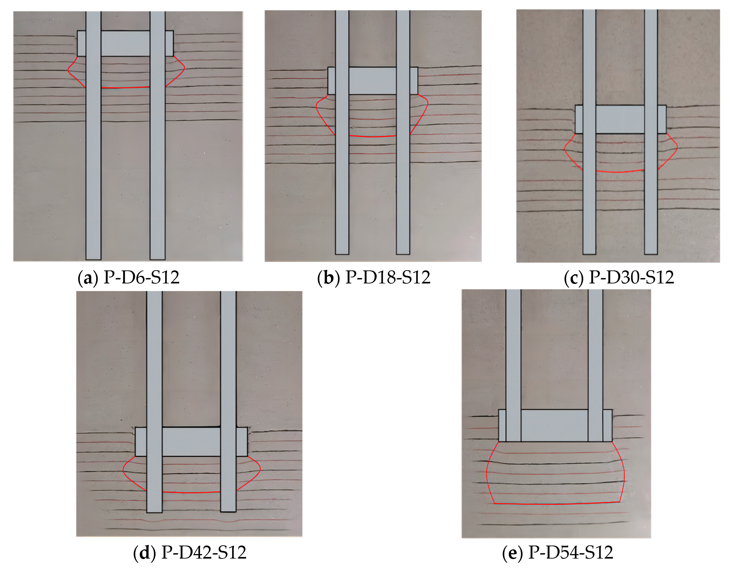
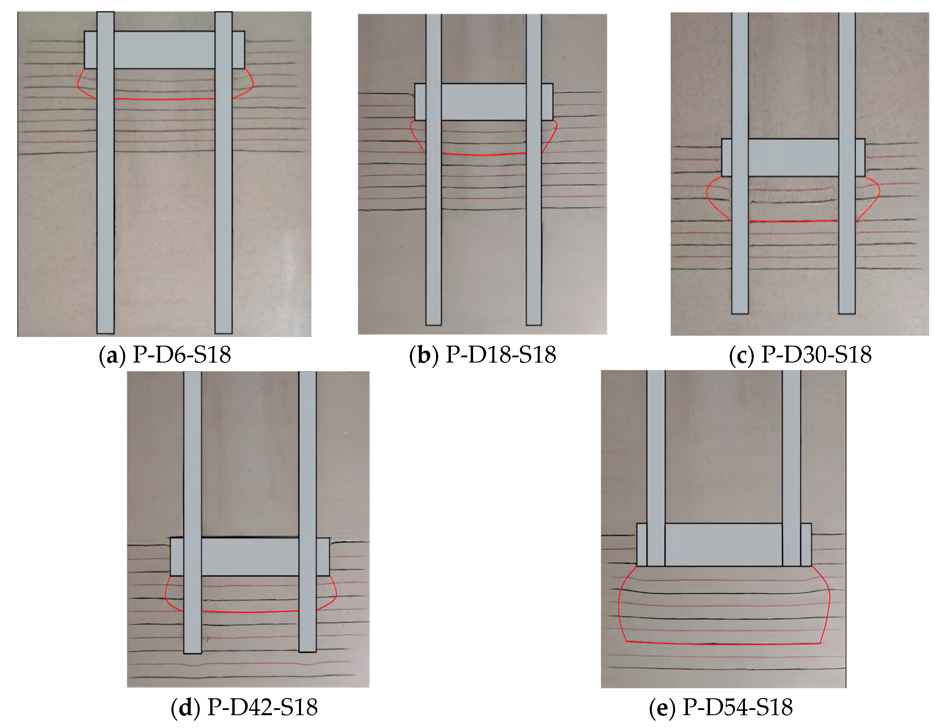
As shown in Figure 14, when the pile spacing is 4D, the load-sharing ratio of the continuously solidified part and pile lateral friction resistance remain basically unchanged with the increasing burial depth. Among them, the ratio of the continuously solidified part was about 33%, and the ratio of pile lateral friction resistance was about 63%. When the pile spacing was 6D, with the increasing burial depth of the continuously solidified part, the ratio of pile lateral friction resistance gradually decreased, while the load-sharing ratio of the continuously solidified part gradually increased with the increasing burying depth and even exceeded the pile lateral friction resistance when the burying depth reached 18D. At the same time, no matter whether the pile spacing was 4D or 6D, the bearing capacity of the pile end was no more than 5% after setting up the continuously solidified part, which indicated that the bearing capacity of the SCS group pile is mainly borne by the continuously solidified part and the pile lateral friction resistance.

4.4. Failure Mode

As shown in Figure 15 and Figure 16, when the model pile reaches the ultimate load, a high strain damage zone occurs in the foundation soil around the pile at the bottom of the continuously solidified part. For the same pile spacing, the damage pattern of the foundation soil at the bottom of the continuously solidified part from the burial depths of 2D to 14D was basically the same, and the high-strain damage zone was in the form of “abacus beads”. When the continuously solidified depth reached 18D, the foundation soil exhibited an “inverted bowl” type of damage. At a pile spacing of 4D, the height of the damage zone was approximated via the continuously solidified burial depths from 2D to 14D, which was about 3D. When the burial depth of the continuously solidified part reached 18D, the height of the damage zone increased to 4D. At a pile spacing of 6D, the height of the damage zone was approximated via the continuously solidified burial depths from 2D to 14D, which was approximately 2D. When the continuously solidified burial depth reached 18D, the height of the damage zone also increased to 4D. The length of the damage zone increased with the enlargement of pile spacing, but the spread of the high-strain damage zone around the perimeter of the continuously solidified part did not vary much and kept about a 0.5–1.5D unilaterally.

4.5. Discussion

(1) The SCS group foundation has obvious advantages. First, after the target layer of a certain thickness is reinforced, all the foundation piles are connected in a specified depth, which avoids the gradual failure of a single pile after loading. Second, this technology leverages the in situ reinforcement potential of sandy soil or gravel soil and makes it possible to increase the strength of the target reinforcement layer at a lower cost. As a result, the purpose of shortening pile length, reducing cost and settlement is achieved. This system can address high or ultra-high bearing capacity demands of group pile foundations in limited areas cost-effectively, such as for bridges, wind turbines, oil platforms, and other large or ultra-large foundations.
However, there are some constraints. The SCS group pile foundation is only suitable for deep soft ground conditions, particularly for soft soil and sandy soil interlayer foundations. To ensure the reliable connection between the solidified part and the pile, the solidified part is required to have a certain strength and thickness.
(2) According to the technical specification for building pile foundation [38], the theoretical formula for the ultimate bearing capacity of the new pile type is derived by introducing the coefficient of the number of foundation piles and considering the coefficient of the size effect of the end resistance of the large-diameter pile:
Q u = t u 1 + u 2 q s i k l i + Ψ p q p k A p  
where   t is the number of foundation piles; u 2 is the perimeter of the continuously solidified part (unit: m); u 1 is the perimeter of the foundation pile body (unit: m); q s i k is the standardized value of ultimate lateral resistance of layer i soil on the side of the pile (unit: kPa); l i is the thickness of layer i soil around the pile (unit: m); Ψ p is the size effect coefficient of end resistance for large-diameter piles; q p k is the standard value of ultimate end resistance (unit: kPa); and A p is the area of the pile end (unit: m 2 ), i.e., the area of the solidified part section.
The model piles used for this test were scaled-down models of 1/20th of the real bored piles, and the model piles with the greatest depth of solidified part were selected. According to the size of the model pile and its test data, the ultimate bearing capacity is scaled up to obtain the test value of the ultimate bearing capacity of the bored pile, which is compared with the calculated value using the theoretical formula, and the relationship between the calculated value and the model test value can be obtained, as shown in Figure 17 (note: the figure contains additional experimental data not listed in this paper for space limitations, which will be published in another paper.)
The correlation coefficient between the experimental and calculated values can be calculated according to the Pearson’s correlation coefficient formula, which is defined as:
r = x x ¯ y y ¯ x x ¯ 2 y y ¯ 2
where   r is the correlation coefficient, x is the calculated value, y is the test value, x ¯ is the average of the calculated values, and   y ¯ is the average of the test values.
The equation calculated 0.9 < r = 0.962 < 1, which signifies an extreme correlation, verifying the accuracy of the present ultimate bearing capacity equation.
(3) The bearing capacity of the SCS group pile foundation as a whole increases with the increase in continuously solidified part burial depth; this is due to the fact that when the group pile reaches its ultimate bearing capacity, the stress concentration will appear at the bottom of the solidified part. The greater the burial depth of the solidified part, the greater the overloading of the two sides above the horizontal plane of the bottom of the continuously solidified part, and the less likely occurrence of the destruction of the sand body at the bottom of the solidified part, according to the theory of the ultimate bearing capacity of the Terzaghi. Moreover, the larger the pile spacing, the larger the contact area between the bottom of the solidified part and the sand, so the solidified part can provide greater bearing capacity. On the other hand, due to the group piles in the process of compression, there is a pile side friction force and continuously solidified part bearing capacity play out of synchronization caused by the displacement of uncoordinated problems, so 4D pile spacing of the group pile foundation in the solidification of the 42 cm depth of burial causes a reversal of the reduction in ultimate load carrying capacity.
(4) The actual soil layer is not uniform, and the most suitable soil layer for strengthening is often not at the bottom of the pile. In other words, the sandy soil is most suitable for solidification, but the sand layer is not always at the bottom of the pile. Therefore, the different embedment depths of consolidation positions have been discussed.
(5) We also note the important impact of artificial intelligence algorithms and artificial neural networks in engineering applications [39,40,41,42,43,44,45,46], especially in pile foundation design and related problems. It is convenient to extend this series of problems in future research so as to improve the subsequent application and evaluation of the SCS group pile foundation.

5. Conclusions

Compared with the traditional group pile foundation, the advantages of the SCS group pile foundation are enormous. The setting of the continuously solidified part has a significant impact on its compressive bearing characteristics. From the results, the following conclusions have been drawn:
(1)
The ultimate compressive bearing capacity of the SCS group pile foundation is increased by four to nine times compared with the traditional group pile foundation. When the pile spacing is 4–6D, designing for a continuously solidified depth greater than 14D is recommended.
(2)
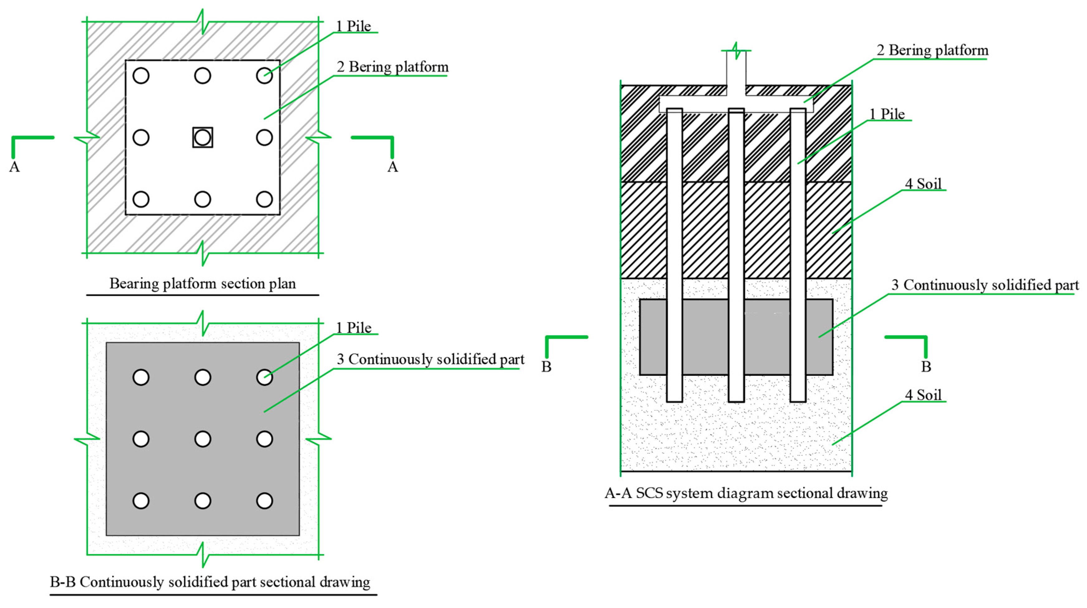
The setting of the continuously solidified part causes the pile axial force to be significantly reduced at its top and bottom. The lateral resistance gradually decreases with depth at 2D of continuously solidified depth; the lateral resistance gradually increases with depth at 18D of continuously solidified depth; the lateral resistance of other model piles first increases and then decreases with depth, and the maximum value is located at the continuously solidified part and is obviously larger than that of other pile sections. When the depth of the continuously solidified part reaches the maximum value, the lateral resistive force provided by it also reaches the maximum.
(3)
The bearing capacity of the pile end is no more than 5% after setting up the continuously solidified part, and the bearing capacity of the SCS group pile is mainly borne via the continuously solidified part and the pile lateral friction resistance.
(4)
For the same pile spacing, the damage pattern of the foundation soil at the bottom of the continuously solidified part from the burial depth of 2D to 14D is basically the same, and the high-strain damage zone is in the form of “abacus beads”. When the continuously solidified depth reaches 18D, the foundation soil exhibits “inverted bowl” damage.
Due to the limitations of indoor modeling tests in quantitative prediction, qualitative analysis and normalization of results were used in this study. Centrifugal modeling tests and field tests will be conducted in subsequent studies.

Author Contributions

T.S. and J.Y. provided the concept and performed the tests. Z.L. designed the tests and performed data analysis. F.Y. carried out data processing. C.W. edited the draft of manuscript. D.X. and S.L. contributed to revising the draft of manuscript. All authors have read and agreed to the published version of the manuscript.

Funding

This research was funded by the National Natural Science Foundation of China (grant no. 51779235, 52078474 and 52378380).

Data Availability Statement

The data presented in this study are available on request from the corresponding author. The data are not publicly available due to privacy.

Conflicts of Interest

Tao Sun, Chen Wang, Dongjing Xu, Zhiyuan Lin, Junjie Yang, Shengmei Liu, and Fakai Yang declare that they have no conflicts of interest.

References

  1. Lv, Y.; Liu, H.; Ding, X.; Kong, G. Field Tests on Bearing Characteristics of X-Section Pile Composite Foundation. J. Perform. Constr. Facil. 2012, 26, 180–189. [Google Scholar] [CrossRef]
  2. Lv, Y.; Li, X.; Wang, Y. Centrifuge and numerical modeling of geometrical effects on XCC piled raft. Soils Found. 2021, 60, 1405–1421. [Google Scholar] [CrossRef]
  3. Ma, T.; Zhu, Y.; Yang, X.; Ling, Y. Bearing Characteristics of Composite Pile Group Foundations with Long and Short Piles under Lateral Loading in Loess Areas. Math. Probl. Eng. 2018, 2018, 8145356. [Google Scholar] [CrossRef]
  4. Yuan, B.; Sun, M.; Xiong, L.; Luo, Q.; Pradhan, S.P.; Li, H. Investigation of 3D deformation of transparent soil around a laterally loaded pile based on a hydraulic gradient model test. J. Build. Eng. 2020, 28, 101024. [Google Scholar] [CrossRef]
  5. Han, S.J.; Lee, J.; Kim, J.H.; Kim, M.S.; Kim, K.S.; Oh, Y.H. Experimental shear test of deep PHC piles reinforced by infilled concrete and shear rings. J. Build. Eng. 2022, 46, 103812. [Google Scholar] [CrossRef]
  6. Wang, B.; Xu, G.; Shi, M. Application and analysis of reinforcement effect of soil between double-row piles in deep foundation pits located in 1st terrace near Yangtze River. Chin. J. Geotech. Eng. 2014, 36, 236–241. [Google Scholar]
  7. Fan, J.; Liu, X.; Li, J. Analysis of the Supporting Effect of Double Row Piles Reinforcement. Geotech. Eng. Tech. 2015, 3, 132–134. [Google Scholar]
  8. Wang, X.; Liao, Z.; Zheng, T.; Zhu, D. Model test study on bearing characteristics of double-row piles based on reinforcement effect of soil around piles. J. Civ. Environ. Eng. 2021, 43, 19–25. [Google Scholar]
  9. Yang, M.; Yao, L.; Wang, G. Study of centrifuge model test and numerical simulation on soil arching in space of piles. Rock Soil Mech. 2008, 29, 817–822. [Google Scholar]
  10. Yan, B.; Hu, K.; Cao, M. Analysis of the Influences of Reinforced Soil Parameters between Piles on Double Row Pile Supporting Structure. Chin. J. Undergr. Space Eng. 2022, 18, 226–232. [Google Scholar]
  11. Huang, G.; Hui, G.; Mei, G. Comparative Experiment Study on Pedestal Piles. Chin. J. Rock Mech. Eng. 2006, 25, 1922–1926. [Google Scholar]
  12. Zhang, L.; Wang, X. Comparison on load-bearing characteristics among equal diameter pile, belled pile and branch pile. J. Chang’Univ. 2016, 36, 37–44. [Google Scholar]
  13. Wang, W.; Wu, J.; Wang, X. Ultimate load tests on bearing and deformation behavior of uplift piles with enlarged base. Chin. J. Geotech. Eng. 2016, 38, 1330–1338. [Google Scholar]
  14. Zhang, M.; Cui, W.; Xu, P.; Niu, Y. Research on soil displacement field around the squeezed branch pile under vertical load. Chin. J. Rock Mech. Eng. 2017, 36, 3569–3577. [Google Scholar]
  15. Zhang, Y.; Chen, P.; Zhao, Z. Experimental study on squeezed branch pile foundation in soft soil ground. Chin. J. Geotech. Eng. 2013, 35, 990–997. [Google Scholar]
  16. Chen, F.; Wu, K.; He, S. Field tests on load transfer performances of squeezed branch piles. Chin. J. Geotech. Eng. 2013, 35, 990–993. [Google Scholar]
  17. Ju, Y.; Liang, R.; Bai, X.; Zhang, S. Experimental Study on The Failure Pattern of Expanded Plates of The Squeezed Branch Pile. Eng. Mech. 2013, 30, 188–194. [Google Scholar]
  18. Li, F.; Song, Q. Analysis of bearing characteristics of variable section piles based on intermittent conditions. Build. Struct. 2019, 49, 800–805. [Google Scholar]
  19. Wang, Y.; Xu, L.; Li, B.; Xu, C. Finite element numerical study on the axial bearing behaviors and factors of squeezed branch pile. China Civ. Eng. J. 2015, 45, 158–162. [Google Scholar]
  20. Ye, Q.; Wang, G.; Yang, L.; Jin, Z.-X. Analysis of influence of MJS (metro jet system) pile construction on adjacent existing buildings in soft soil area in Ningbo. Tunn. Constr. 2017, 37, 1379. [Google Scholar]
  21. Zhang, K.; Wang, S.; Cui, Q.; Wang, J. Experimental Study on the Influence of Grouting on the Compressive Bearing of Micro Steel Pipe Pile. Chin. J. Undergr. Space Eng. 2022, 18, 202–207. [Google Scholar]
  22. Wang, G.; Liu, X.; Sun, D.; Shao, Z.; Yao, Y. Experimental Study on the Shear Properties of Soil around Piles with Permeation Grouting. Appl. Sci. 2023, 13, 621. [Google Scholar] [CrossRef]
  23. Zong, Z.; Lu, X.; Li, Q.; Zhang, Z. An experimental study of bearing capacity of post-grouting jacked steel pipe micropiles. Rock Soil Mech. 2017, 38, 323–329. [Google Scholar]
  24. Karimi, A.-H.; Eslami, A. Physical modelling for pile performance combined with ground improvement using frustum confining vessel. Int. J. Phys. Model. Geotech. 2018, 18, 162–174. [Google Scholar] [CrossRef]
  25. Huang, T.; Gong, W.; Li, H. Static load tests on super-long piles with base post-grouting. Chin. J. Geotech. Eng. 2011, 33, 119–123. [Google Scholar]
  26. Wang, G.; Shu, W.; Zhao, Z.; Xu, Q.; Zhang, Y. Research on load bearing characteristics and pile group effect of screw pile under vertical loads. J. Zhejiang Univ. Technol. 2022, 50, 291–298. [Google Scholar]
  27. Sabri MM, S.; Vatin, N.I.; Ponomarev, A.B.; Nurmukhametov, R.R.; Kostyukov, I.I. Settlement of Soil Reinforced with Vertical Fiberglass Micro-Piles. Materials 2022, 15, 4744. [Google Scholar] [CrossRef]
  28. Liu, S.; Luo, F.; Zhang, G. Pile reinforcement behavior and mechanism in a soil slope under drawdown conditions. Bull. Eng. Geol. Environ. 2020, 80, 4097–4109. [Google Scholar] [CrossRef]
  29. Sun, T. The Utility Model Relates to a Pile Group System Continuously Reinforced by Soil between Piles and a Construction Method Thereof. Chinese Patent CN106759424A, 31 May 2017. [Google Scholar]
  30. Mao, Z.; Yang, L.; Li, J. Experimental Study on Compaction Effect between Metro Jet System Method and High-Pressure Jet Grouting Pile (Double-Tube). Tunn. Constr. 2021, 41, 1699. [Google Scholar]
  31. Dolati, S.S.K.; Mehrabi, A. Review of available systems and materials for splicing prestressed-precast concrete piles. Structures 2021, 30, 850–865. [Google Scholar] [CrossRef]
  32. Ohsutka, T.; Aramaki, G.; Koga, K. Soil improvement of soft ground around pile foundation in earthquake-resistant design. Lowl. Technol. Int. 2004, 6, 42–54. [Google Scholar]
  33. Garnier, J.; Konig, D. Scale effects in piles and nails loading tests in sand. Centrifuge 1998, 98, 205–210. [Google Scholar]
  34. Song, Q.; Yang, J.; Sun, T.; Li, F.; Yang, N. Model tests on bearing behavior of dynamic deformation process of uplift piles with enlarged base. Period. Ocean. Univ. China 2021, 51, 105–112. [Google Scholar]
  35. Sun, T.; Cui, X.Z.; Sun, Y.F.; Han, R.N.; Ma, R.J.; Yang, J.J.; Chang, Y.J. Model tests on uplift capacity of double-belled pile influenced by distance between bells. J. Cent. South Univ. 2022, 29, 1630–1640. [Google Scholar] [CrossRef]
  36. Sun, T.; Yang, J.; Zhao, H. Study on Compressive Load-Bearing Characteristics of Section-Variable Reinforced Jet-Grouting & Mixing Cement-Soil Pile by Indoor Model Tests. Period. Ocean. Univ. China 2012, 43, 20–27. [Google Scholar]
  37. Yang, J.; Ochhiai, H. A Study on bearing capacity of geogrid-rein-forced foundation ground. Proc. Geotextile Symp. 1991, 6, 15–23. [Google Scholar] [CrossRef]
  38. JGJ 94-2008[S]; Technical Code for Building Pile Foundations. China Architecture & Building Press: Beijing, China, 2008. (In Chinese)
  39. Wu, Z.; Luo, G.; Yang, Z.; Guo, Y.; Li, K.; Xue, Y. A comprehensive review on deep learning approaches in wind forecasting applications. CAAI Trans. Intell. Technol. 2022, 7, 129–143. [Google Scholar] [CrossRef]
  40. Benbouras, M.A.; Petrişor, A.I.; Zedira, H.; Ghelani, L.; Lefilef, L. Forecasting the Bearing Capacity of the Driven Piles Using Advanced Machine-Learning Techniques.apllied. Appl. Sci. 2021, 11, 10908. [Google Scholar] [CrossRef]
  41. Gasparin, A.; Lukovic, S.; Alippi, C. Deep learning for time series forecasting: The electric load case. CAAI Trans. Intell. Technol. 2022, 7, 1–25. [Google Scholar] [CrossRef]
  42. Khan, J.; Lee, E.; Kim, K. A higher prediction accuracy–based alpha–beta filter algorithm using the feedforward artificial neural network. CAAI Trans. Intell. Technol. 2022; Early View. [Google Scholar]
  43. Hsiaoi, I.; Chung, C. AI-infused semantic model to enrich and expand programming question generation. J. Artif. Intell. Technol. 2022, 2, 47–54. [Google Scholar] [CrossRef]
  44. Deng, Y.; Zeng, Z.; Jha, K.; Huang, D. Problem-Based Cybersecurity Lab with Knowledge Graph as Guidance. J. Artif. Intell. Technol. 2022, 2, 55–61. [Google Scholar] [CrossRef]
  45. Mohanty, R.; Suman, S.; Das, S.K. Prediction of vertical pile capacity of driven pile in cohesionless soil using artificial intelligence techniques. Int. J. Geotech. Eng. 2018, 12, 209–216. [Google Scholar] [CrossRef]
  46. Jia, Z.; Wang, W.; Zhang, J.; Li, H. Contact High-Temperature Strain Automatic Calibration and Precision Compensation Research. J. Artif. Intell. Technol. 2022, 2, 69–76. [Google Scholar]
Figure 1. SCS system diagram.
Applsci 13 12850 g001
Figure 2. The particle gradation curve.
Applsci 13 12850 g002
Figure 3. Relationship between the drop distance and the relative density.
Applsci 13 12850 g003
Figure 4. Wax-filled half mold pile.
Applsci 13 12850 g004
Figure 5. Design of the test scheme (unit: mm). (a) Without a continuously solidified part; (b) continuously solidified 4D pile spacing; and (c) continuously solidified 6D pile spacing.
Applsci 13 12850 g005
Figure 6. Load–settlement curve of the A-S18 pile and the P-D6-S18 pile.
Applsci 13 12850 g006
Figure 7. The ultimate bearing capacity of the model pile was determined using the hyperbolic fitting method.
Applsci 13 12850 g007
Figure 8. Load–settlement curve of model test. (a) Load–settlement curve at 4D pile spacing. (b) Load–settlement curve at 6D pile spacing.
Applsci 13 12850 g008
Figure 9. Relation curve between the ultimate bearing capacity of the model pile and the solidified buried depth.
Applsci 13 12850 g009
Figure 10. Axial force distribution curve of the pile body under 4D pile spacing.
Applsci 13 12850 g010
Figure 11. Axial force distribution curve of the pile body under 6D pile spacing.
Applsci 13 12850 g011
Figure 12. Lateral friction resistance distribution under 4D pile spacing.
Applsci 13 12850 g012
Figure 13. Lateral friction resistance distribution under 6D pile spacing.
Applsci 13 12850 g013
Figure 14. Load-sharing ratio at different buried depths.
Applsci 13 12850 g014
Figure 15. The 4D pile spacing foundation soil failure model.
Applsci 13 12850 g015
Figure 16. The 6D pile spacing foundation soil failure model.
Applsci 13 12850 g016
Figure 17. Comparison of calculated values and model test values.
Applsci 13 12850 g017
Table 1. Basic physical properties of quartz sand.
Maximum Dry Density
dmax/g·cm−3)
Minimum Dry Density
dmin/g·cm−3)
Specific Gravity of Soil Particles
(Gs)
Water Content
(ω/%)
Angle of Internal Friction
(φ/°)
Cohesion
(c/kPa)
1.621.312.670.04238.390
Table 2. Ultimate compressive capacity and settlement of each group of model piles.
Pile DiameterTest NumberUltimate Compressive Capacity (N)Settlement (mm)Ultimate Compressive Capacity Ratio
4DA-S12183.27.061.0
P-D6-S121210.114.746.6
P-D18-S121101.716.596.0
P-D30-S121384.415.477.6
P-D42-S121337.712.247.3
P-D54-S121850.915.5310.1
6DA-S18321.38.711.0
P-D6-S181555.216.215.0
P-D18-S181557.116.295.0
P-D30-S181756.218.375.6
P-D42-S181889.219.796.0
P-D54-S182509.614.938.0
Disclaimer/Publisher’s Note: The statements, opinions and data contained in all publications are solely those of the individual author(s) and contributor(s) and not of MDPI and/or the editor(s). MDPI and/or the editor(s) disclaim responsibility for any injury to people or property resulting from any ideas, methods, instructions or products referred to in the content.

