


Investigation of Inner Lining Loss and Correlation with Steel Structure Ovality in Rotary Kilns


Abstract
1. Introduction
- Shape: the shape of the kiln as a whole, including any changes from a perfect cylinder.
- Size: the length and width of the kiln, as well as the depth.
- Symmetry: the degree to which the kiln is symmetric, including any differences from perfect symmetry.
- Wear and tear: the amount of wear and tear on the surface of the kiln, including any places where there is a lot of damage or wear.
- Ovality: the extent to which the cross-section of the kiln is circular or elliptical.
- Displacement: the amount that the kiln moves or shifts.
- Twist: the amount that the shaft of the kiln is turned.
- Deformations: any changes to the surface of the kiln.
- Checking the refractory lining for damage or wear that could cause the shell to overheat and change shape.
- Check for the wear or misalignment of the ring and support wheels, which can cause the shell to load and change shape.
- Check for wear or damage to the thrust rollers and thrust bearings, which can cause axial thrust loads that can cause the shell to bend.
- Making sure the drive system is aligned and working right, which can affect how the shell is loaded and where it is placed.
- Checking the shell for signs of cracks, deformation, or other damage, and fixing or replacing it as needed.
- Keep an eye on the kiln’s temperature and other conditions and make changes as needed to prevent damage to the shell.
2. Materials and Methods
- Total station measurement: measuring the size of the kiln with an electronic surveying tool.
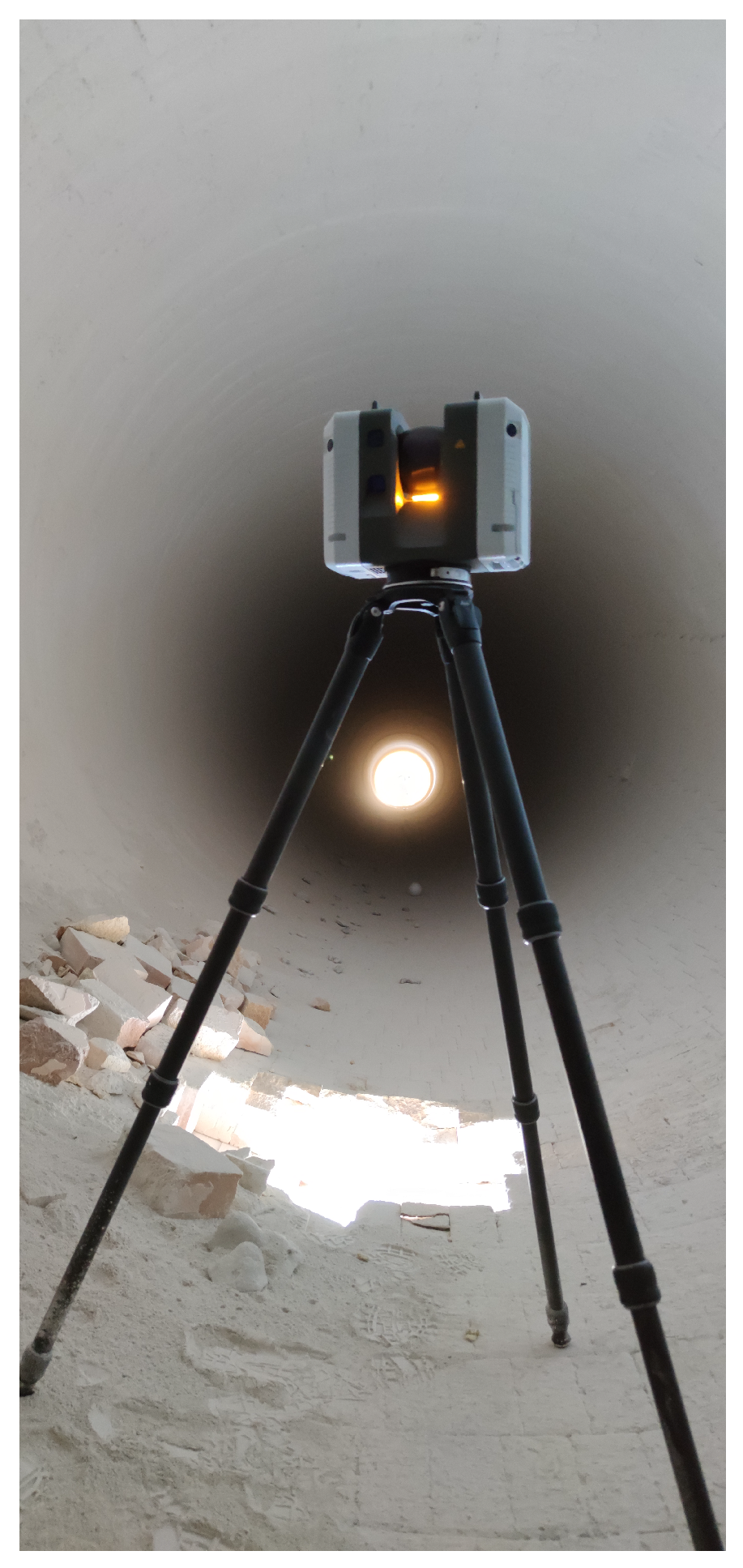
- Laser scanning: using laser scanners to take point cloud data of the kiln’s surface and then processing the data to make a 3D model of the kiln.
- Terrestrial photogrammetry: A 3D model of the kiln is made from a collection of high-resolution photos taken from different angles.
- Infrared thermography: thermal imaging cameras are used to find areas of wear or damage on the surface of the oven where the temperature changes.
- Ultrasonic testing: the application of ultrasound sensors to measure the thickness of the kiln’s shell and find places where it is getting thinner or eroding.
- Vibration analysis: using sensors to watch the kiln’s vibration patterns and find any strange moves or vibrations that could hint at a possible problem.
- Scanning rotary kiln exterior.
- Scanning rotary kiln interior with spherical targets.
- Scanning lime firing area to connect interior and exterior.
- Registration of scans in Leica Cyclone Register360.
- Clean scan from unnecessities.
- Export separately interior and exterior scans.
- Estimating axis of rotary kiln by fitting cylinder on exterior scans.
- Modelling perfect state of inner lining.
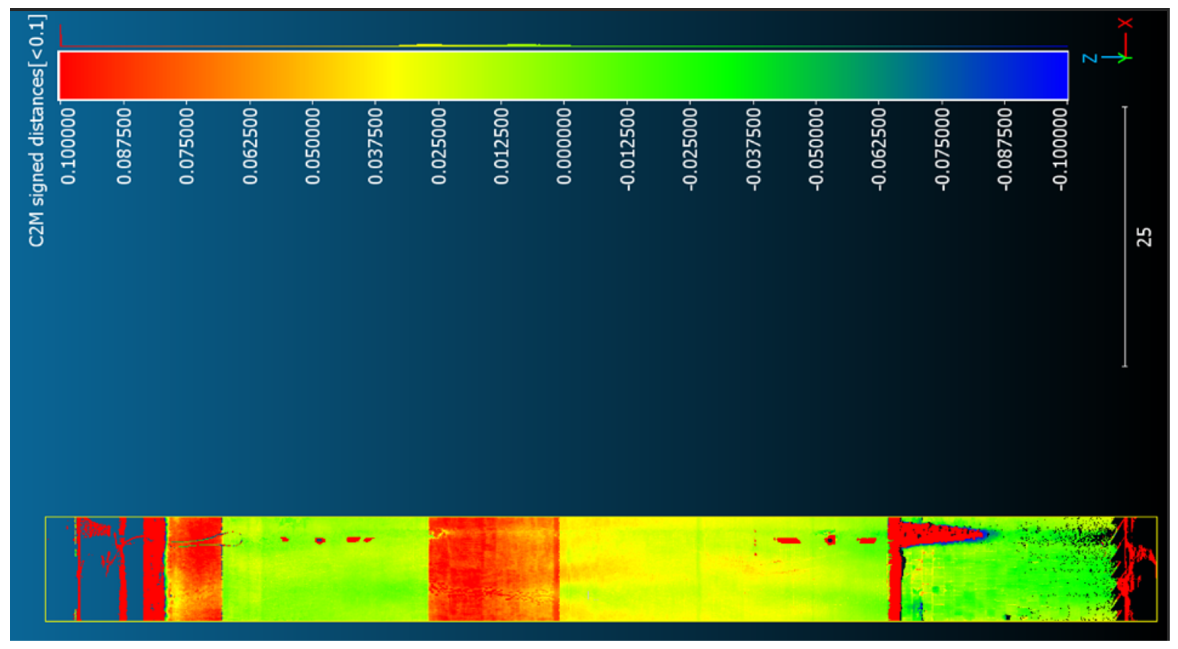
- Estimating lining loss by comparing model of perfect state with interior scans.
2.1. RANSAC Algorithm
2.2. Laser Scanner Working Principles
- Rotary kiln ovality analysis.
- Radius difference along rotary kiln.
- Centrality of rotary kiln steel strip.
- Material loss of riding rings.
- Correlation of inner lining loss and ovality.
3. Results
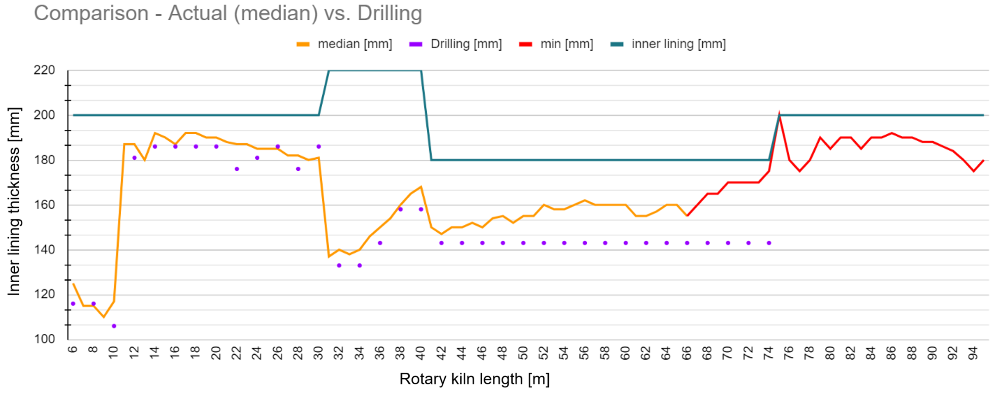
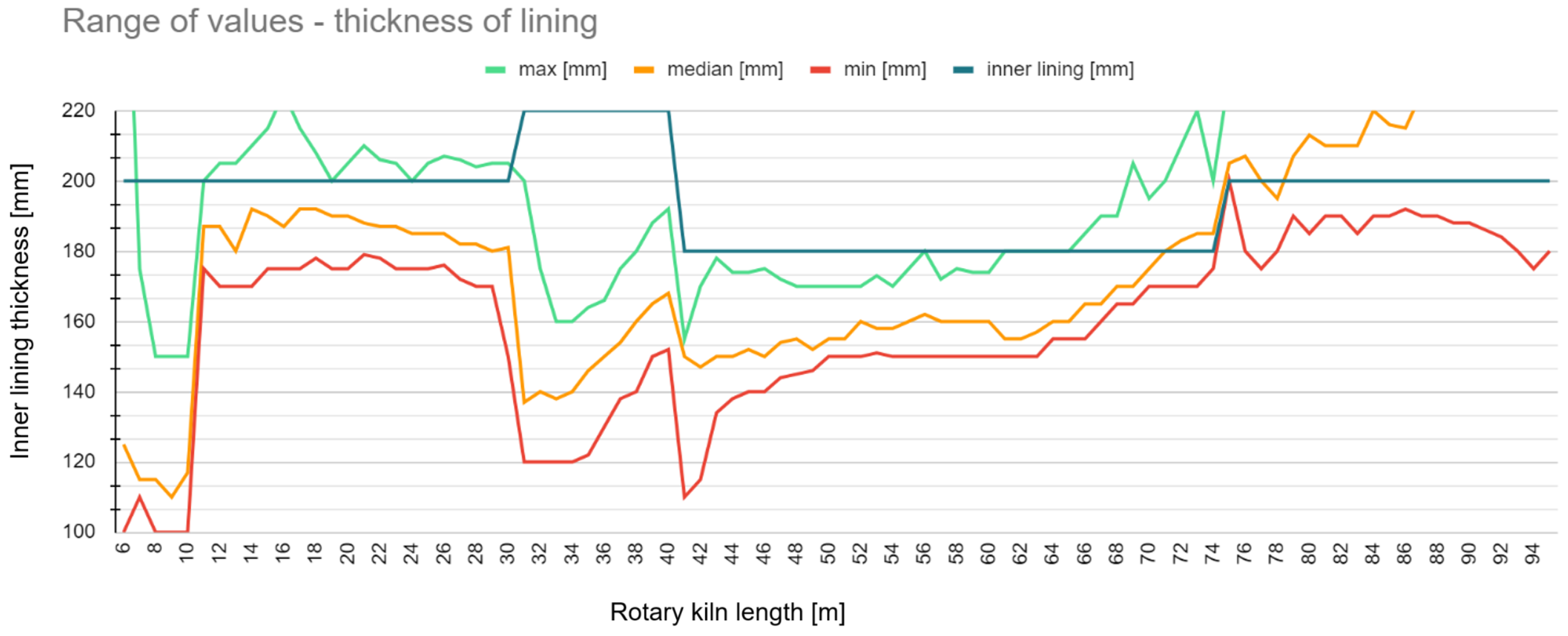
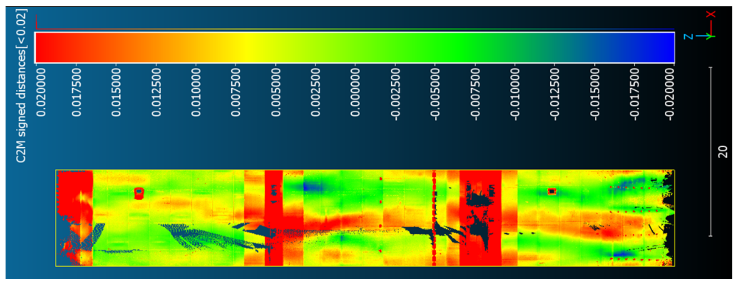
3.1. Loss of Inner Lining
3.2. Ovality
3.3. Radius Difference
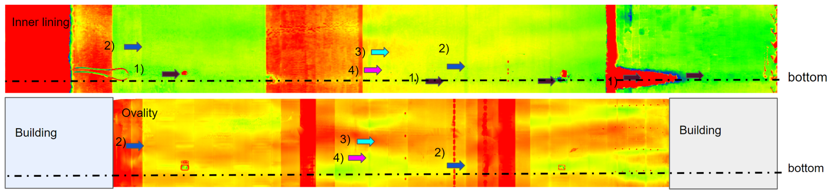
3.4. Correlation of Inner Lining Loss and Ovality
3.5. Riding Ring Materials Loss
4. Discussion
5. Conclusions
Author Contributions
Funding
Institutional Review Board Statement
Informed Consent Statement
Data Availability Statement
Acknowledgments
Conflicts of Interest
Abbreviations
| RANSAC | Random sample consensus |
| TLS | Terrestrial laser scanning |
References
- Feber, N.; Jandera, M.; Křemen, T.; Rossi, B. Experimental study of welded austenitic stainless steel I-section beam-columns. In Proceedings of the EUROSTEEL 2021 Sheffield—Steel’s Coming Home, Sheffield, UK, 1–3 September 2021; Ernst Sohn: Berlin, Germany, 2021; Volume 4, pp. 2255–2261, ISSN 2509-7075. [Google Scholar]
- Mára, M.; Máca, P.; Sovják, R.; Šedina, J.; Curbach, M. The influence of various loading rates on concrete fracture surface areas. Mater. Today Proc. 2020, 32, 219–223. [Google Scholar] [CrossRef]
- Pavelka, K.; Šedina, J. Use of photogrammetrical methods and laser scanning for documentation of deformation at sequential loading. In Proceedings of the International Conference on Engineering Sciences and Technologies, High Tatras, Slovakia, 27–29 May 2015; ISBN 978-80-553-2042-7. [Google Scholar]
- Xiao, Y.; Li, X.; Chen, X. General solution to kiln support reactions and multi-objective fuzzy optimization of kiln axis alignment. Struct. Multidiscip. Optim. 2008, 36, 319–327. [Google Scholar] [CrossRef]
- Dhillon, B.S. Multiaxial fatigue life prediction of kiln roller under axis line deflection. Appl. Math. Mech. 2010, 31, 205–214. [Google Scholar] [CrossRef]
- Pazand, K.; Panahi, M.S.; Pourabdoli, M. Simulating the mechanical behavior of a rotary cement kiln using artificial neural networks. Mater. Des. 2009, 30, 3468–3473. [Google Scholar] [CrossRef]
- Ramanenka, D.; Stjernberg, J.; Jonsén, P. FEM investigation of global mechanisms affecting brick lining stability in a rotary kiln in cold state. Eng. Fail. Anal. 2016, 59, 554–569. [Google Scholar] [CrossRef]
- Peray, W. The Rotary Cement Kiln; Edward Arnold: New York, NY, USA, 1986; pp. 227–343. [Google Scholar]
- Ozek Makina. Available online: http://www.rotarykiln.net (accessed on 6 October 2020).
- NAK Kiln Services. Available online: https://nak-kiln.com (accessed on 6 October 2020).
- Zheng, K.; Zhang, Y.; Liu, L.; Zhao, C. Metoda računalnog mjerenja odstupanja ravnosti cilindra rotacijske peći. Teh. Vjesn. 2017, 24, 1297–1305. [Google Scholar] [CrossRef]
- Rusinski, E.; Stamboliska, Z.; Moczko, P. Proactive control system of condition of low-speed cement machinery. Autom. Constr. 2013, 31, 313–324. [Google Scholar] [CrossRef]
- Rahman, M.M.; Nijemeisland, M.; Wesselink, R.J.; Luding, S. Coupled CFD-DEM simulation of heat transfer and particle motion in a rotary kiln. Chem. Eng. Sci. 2014, 111, 657–671. [Google Scholar] [CrossRef]
- Khan, M.S.; Ahmad, I. CFD modeling of rotary cement kilns. Miner. Eng. 2013, 43–44, 57–63. [Google Scholar]
- Zheng, K.; Liu, W.; Guo, F. Coupling heat transfer model of rotating cement kiln with accompanying evaporation-drying process. J. Therm. Sci. 2011, 20, 245–251. [Google Scholar]
- Li, C.; Feng, Y.; Hu, Z.; Luo, S. Numerical simulation of the influence factors for rotary kiln in temperature field and stress field. J. Univ. Sci. Technol. Beijing 2006, 28, 446–451. [Google Scholar]
- Larsson, I.A.S. The Aerodynamics of an Iron Ore Pelletizing Rotary Kiln. Fluids 2022, 7, 160. [Google Scholar] [CrossRef]
- Žiga, A.; Karač, A.; Vukojević, D. Analytical and numerical stress analysis of the rotary kiln ring. Teh. Vjesn. 2013, 20, 941–946. [Google Scholar]
- Goshayeshi, H.R.; Poor, F.K. Modeling of Rotary Kiln in Cement Industry. Energy Power Eng. 2016, 8, 23. [Google Scholar] [CrossRef]
- Saidur, R.; Hossain, M.S.; Islam, M.R.; Fayaz, H.; Mohammed, H.A. A review on kiln system modeling. Renew. Sustain. Energy Rev. 2011, 15, 2487–2500. [Google Scholar] [CrossRef]
- Li, X.; Shen, Y.; Wang, S. Dynamic modeling and analysis of the large-scale rotary machine with multi-supporting. Shock Vib. 2011, 18, 53–62. [Google Scholar] [CrossRef]
- EN 1993-1-1; Eurocode 3: Design of Steel Structures. European Committee for Standardization: Brussels, Belgium, 1993. Available online: https://www.phd.eng.br/wp-content/uploads/2015/12/en.1993.1.1.2005.pdf (accessed on 23 October 2020).
- Świtalski, M. The Measurement of Shell’s Elastic Ovality as an Essential Element of Diagnostic of Rotary Drum’s Technical State. Diagnostyka 2010, 53, 37–47. [Google Scholar]
- Available online: https://www.zmp.com.pl/shelltester (accessed on 6 October 2020).
- Krystowczyk, Z. Geometry Measurements of Kiln Shell in Dynamic Conditions. Cem. Build. Mater. Rev. 2004, 16, 34–37. [Google Scholar]
- Mogil’Nyj, S.G.; Sholomitskii, A.A.; Lagutina, E.K.; Sal’Nikov, V.G. The influence of refraction in geodetic measurements of rotary kilns. In Proceedings of the 25th International Symposium on Atmospheric and Ocean Optics: Atmospheric Physics, Novosibirsk, Russia, 30 June–5 July 2019. [Google Scholar]
- Mogilny, S.; Sholomitskii, A. Precision analysis of geometric parameters for rotating machines during cold alignment. Procedia Eng. 2017, 206, 1709–1715. [Google Scholar] [CrossRef]
- Jia, D.; Zhang, W.; Wang, Y.; Liu, Y. A New Approach for Cylindrical Steel Structure Deformation Monitoring by Dense Point Clouds. Remote Sens. 2021, 13, 2263. [Google Scholar] [CrossRef]
- Kovanič, L.; Blišťan, P.; Zelizňaková, V.; Palková, J.; Baulovič, J. Deformation investigation of the shell of rotary kiln using terrestrial laser scanning (TLS) measurement. Metalurgija 2019, 58, 311–314. [Google Scholar]
- Zhang, Z.; Yin, T.; Huang, X.; Zhang, F.; Zhu, Y.; Liu, W. Identification and Visualization of the Full-Ring Deformation Characteristics of a Large Stormwater Sewage and Storage Tunnel Using Terrestrial Laser Scanning Technology. Energies 2019, 12, 1304. [Google Scholar] [CrossRef]
- Site of Open Corporation Industrial Geodesy. Available online: http://promgeo.com/services/kiln (accessed on 6 October 2020).
- Tucci, G.; Conti, A.; Fiorini, L. Refractory Brick Lining Measurement and Monitoring in a Rotary Kiln with Terrestrial Laser Scanning. In Proceedings of the First International Workshop in Memory of Prof. Raffaele Santamaria on R3 in Geomatics: Research, Results and Review, R3GEO 2019, Naples, Italy, 10–11 October 2019; Revised Selected Papers. Springer: Berlin/Heidelberg, Germany, 2020. [Google Scholar]
- Danila, A. The Detection of the Thermal Processes’ Variations into Rotary Cement Kilns by Thermographic Imaging of the Kiln Outer Shell. In Proceedings of the 2021 25th International Conference on System Theory, Control and Computing (ICSTCC), Iasi, Romania, 20–23 October 2021; pp. 498–503. Available online: https://ieeexplore.ieee.org/abstract/document/9607315 (accessed on 10 January 2019).
- Noshirvani, G.; Shirvani, M.; Askari-Mamani, J.; Nourzadeh, H. Estimation of coating thickness in a rotary kiln by using shell temperature and kiln modeling. ZKG Int. 2013, 11, 58–71. [Google Scholar]
- Lamm, R.; Kirchhoff, S. Optimization of ladle refractory lining, gap and crack detection, lining surface temperature and sand filling of the ladle-taphole by means of a 3D-laser profile-measurement-system that is immersed in a hot ladle to evaluate the entire condition. In Proceedings of the UNITECR 2017, Proceedings 2017, Santiago, Chile, 26–29 September 2017; Available online: http://www.unitecr2017.mundodecongresos.com/abstracts/Paper_rbofbhfxcsxhpgipoispm.pdf (accessed on 10 January 2019).
- Schnabel, R.; Wahl, R.; Klein, R. Efficient RANSAC for point-cloud shape detection. Comput. Graph. Forum 2007, 26, 214–226. [Google Scholar] [CrossRef]
- CloudCompare. Vers. 2.11 Alpha. Available online: http://www.cloudcompare.org/ (accessed on 10 January 2019).
- Kovanič, Ľ.; Blistan, P.; Urban, R.; Štroner, M.; Pukanská, K.; Bartoš, K.; Palková, J. Analytical Determination of Geometric Parameters of the Rotary Kiln by Novel Approach of TLS Point Cloud Segmentation. Appl. Sci. 2020, 10, 7652. [Google Scholar] [CrossRef]
- Bui, T.; Beers, A.C.; van Helden, W.G.J.; Segers, A.J.H.; van Antwerpen, H.J.; van der Stappen, A.F. Integrating axis deviation and deformation control for large industrial rotary kilns. Control Eng. Pract. 2017, 61, 114–125. [Google Scholar] [CrossRef]
- Leica RTC360. Available online: https://leica-geosystems.com/-/media/files/leicageosystems/products/datasheets/leica-rtc360-ds.ashx?la=hu-hu&hash=3C70C6ADDEB8DCA88E48A26739B4A1A6 (accessed on 10 January 2019).
- Fischler, M.A.; Bolles, R.C. Random sample consensus: A paradigm for model fitting with applications to image analysis and automated cartography. Commun. ACM 1981, 24, 381–395. [Google Scholar] [CrossRef]


| Subject | Drilling | TLS |
|---|---|---|
| Measurement time | 2 h | 5 h |
| Processing time | 0 h | 3 h |
| Cover area | 1% | 95% |
| 3D visualisation | no | yes |
| Exact periodic comparison | no | yes |
| Gap detection | no | yes |
| Length of Rotary Kiln | Pearson Correlation Coefficient |
|---|---|
| 6–26 m | 0.38 |
| 26–42 m | 0.47 |
| 42–56 m | 0.57 |
| 56–74 m | 0.36 |
| 74–90 m | 0.44 |
Disclaimer/Publisher’s Note: The statements, opinions and data contained in all publications are solely those of the individual author(s) and contributor(s) and not of MDPI and/or the editor(s). MDPI and/or the editor(s) disclaim responsibility for any injury to people or property resulting from any ideas, methods, instructions or products referred to in the content. |
© 2023 by the authors. Licensee MDPI, Basel, Switzerland. This article is an open access article distributed under the terms and conditions of the Creative Commons Attribution (CC BY) license (https://creativecommons.org/licenses/by/4.0/).
Share and Cite
Zahradník, D.; Vynikal, J.; Pavelka, K. Investigation of Inner Lining Loss and Correlation with Steel Structure Ovality in Rotary Kilns. Appl. Sci. 2023, 13, 12811. https://doi.org/10.3390/app132312811
Zahradník D, Vynikal J, Pavelka K. Investigation of Inner Lining Loss and Correlation with Steel Structure Ovality in Rotary Kilns. Applied Sciences. 2023; 13(23):12811. https://doi.org/10.3390/app132312811
Chicago/Turabian StyleZahradník, David, Jakub Vynikal, and Karel Pavelka. 2023. "Investigation of Inner Lining Loss and Correlation with Steel Structure Ovality in Rotary Kilns" Applied Sciences 13, no. 23: 12811. https://doi.org/10.3390/app132312811
APA StyleZahradník, D., Vynikal, J., & Pavelka, K. (2023). Investigation of Inner Lining Loss and Correlation with Steel Structure Ovality in Rotary Kilns. Applied Sciences, 13(23), 12811. https://doi.org/10.3390/app132312811