Abstract
The flexible bearing is the kernel component of the cam wave generator. In precision transmission applications such as miniature robot joints, flexible bearings are required to have a smaller mass, lower moment of inertia, and larger inner diameter. Based on the theory of conventional rolling bearing, and by considering the working characteristics of flexible bearing for harmonic drive, this paper studies the influence law of structural parameters on the fatigue life of the flexible bearing; achieves a technical approach for expanding the bore size of the standard flexible bearing; and deduces the theoretical formulas applicable to the design of the flexible bearing. The new formula is utilized to improve the design parameters of the flexible bearing. The novel design with smaller diameter and more numbers of rolling elements can meet the above performance requirements compared to the conventional flexible bearing. Under the same conditions of radial deformation and materials used, finite element analysis results show that the maximum equivalent stress in the improved flexible bearing is smaller and that the novel design can meet the strength requirements of the harmonic drive.
1. Introduction
The harmonic drive (HD) is a type of mechanical transmission that relies on the wave generator (WG) to produce controlled elastic deformation wave in flexspline (FS) to realize the motion and power transmission, which is characterized by light weight, small volume, high transmission efficiency, and transmission accuracy. It is composed of three major components of WG, FS, circular spline (CS), and is widely used in the precision servo drives of robots, radars, and machine tools [1].
Flexible bearing (FB) is the core component in cam WG, in applications with high requirements for mass, moment of inertia, size and larger inner diameter for cables or motors passing through, the use of HD with conventional FB limits the space volume available, and leads to the difficulty of components assembling.
The design parameters determine the performance of fatigue life of the FB. Shen et al. [2] utilized the theory of convention rolling bearing (CRB) to calculate the rated dynamic load and equivalent dynamic load of FB, respectively, and the overall fatigue life of FB was directly calculated through the L-P life formula. Ren [3] pointed out the irrationality of the current formula for calculating FB and introduced a reliability correction factor to make it more in line with the actual force situation. Li [4] provided an in-depth analysis of the optimization calculation method for CRB life, and introduced material coefficients and failure probability coefficients to make the calculation results more accurate. Ivanov [5] gave empirical formulas for the main parameters of FB.
FB and CRB have different force characteristics, CRB is subjected to unidirectional radial force during the working process, while FB is subjected to bi-directional radial force, and the range of load distribution is also different, so the use of the original life calculation method of CRB to calculate the FB has certain limitations.
There are many studies on the influence of parameters on rolling bearing performance, for deep groove ball bearing, Wang et al. [6] analyzed the influence of different clearances and different rotational speeds on the internal load of CRB under the action of the same external load. Yang et al. [7] studied the influence law of FB design parameters on the fatigue life of the FS of HD. Guan [8] utilized the geometry of the FB to calculate the permissible load of the FB according to the dynamic load capacity, reflecting the influence law of radial clearance on the load distribution of the bearing. Li [9] used the static analysis model of the FB to study the elements in the FB in motion as well as the change rule of stress. Mahanto et al. [10] studied the stress and strain of HD while inserting the integral and split cams into FS. Liu [11] analyzed various stresses in the outer ring of the FB under the premise that the FS and the FB produce distortion. Hao et al. [12] utilized the theory of thin-walled rings to study the effects of different rolling element numbers and cam WG shapes on the internal load distribution of the bearing. You et al. [13] transformed the load distribution calculation model of the FB into a linear system of equations by using the theory of shells and the principle of superposition, and the results of the calculations were in agreement with the elliptical cam radial displacement distribution law. Weinzapfel et al. [14] modeled the wave cage in CRB based on the discrete element method and investigated the frequency and trajectory characteristics of the cage during operation. Ivanov [5] proposed a method to solve the deformation characteristics and bending stresses of FB after mating with cams by three bending moment equations. Wang et al. [15] verified the accuracy of above method by comparing with FEA.
At present, the most commonly used method for analyzing the mechanical properties of FB is FEA, which is in fine agreement with the results of the Hertzian contact theory [16,17]. Yu et al. [18] analyzed the distribution law of deformation and stress of FB under different structural parameters by FEA method for static analysis. Xiang et al. [19] utilized ANSYS/LS-DYNA and LS-PrePost to carry out dynamic analysis of the FB and obtained the stress distribution laws of each part. Adams et al. [20] investigated the vibration frequency of elliptically deformed FB using experimental measurement data and the finite element method. Zhu et al. [21] determined the location of the maximum equivalent force of the FB based on the triple bending moment equations and FEA.
Ostapski et al. [22] proposed a method to solve the elastic deformation problem of thin-walled shell structures with complex geometric shape in ally nonlinear shell theory and compared it with ANSYS calculation results, drew the conclusion that the contact model in ANSYS is more in line with reality. Pan et al. [23] used FEA simulation to analyze the deformation characteristics of FB after assembly. Based on the analysis of FB by ABAQUS, Zhao et al. [24] found that the fatigue damage of the inner ring is mainly caused by contact stress, the contact fatigue damage and bending fatigue damage of the outer ring occur at the same time, and the fatigue failure of the outer ring occurs before that of the inner ring.
To simulate the actual working condition of FB and reduce the test cost, Qin et al. [25] developed a bearing testing machine that can simulate the motion state of FB under different attitudes of robotic arm. Xin et al. [26] developed a fatigue life test method to simulate the actual operating condition of FB.
Zhang et al. [27] analyzed the effect of parameters of aspect ratio and wall thickness etc. on the contact mechanical features of FS under the action of a forced WG. The FEA method is used to analyze the stress distribution and deformation patterns of convention flexible bearing (CFB) under different loads [28,29]. Mu et al. [30] analyzes the materials microstructure and mechanical properties of FS and FB in domestic and Japanese HD. Wang et al. [31] designed a device for accelerated life test of HD set. The method and program of selection, maintenance and fault diagnosis are provided for rolling bearing [32,33]. Yang et al. [34] proposed a fault diagnosis method for HD set using multi-scale convolutional neural networks (MSCNN). The industry has been committed to developing the HD reducers with larger hollow inner diameter [35]. Jia et al. [36] presented the novel forced wave generator (NFWG) for the HD with a large hollow bore.
In precision HD transmission applications such as miniature robot joints, the HD and the FB are required to have a smaller mass, lower moment of inertia, and larger inner diameter. The inner diameter of the FB is one of the important factors limiting further expansion of the hollow inner diameter of the HD, and there is no relevant design materials for increasing the inner diameter of the FB in the references retrieved so far. Therefore, it is necessary to carry out the modification design for the structural parameters of the CFB in order to increase the inner diameter while the outer diameter remains unchanged. Based on the life theory of CRB [37], by using the first method of L-P theory, this paper deduces the new formula suitable for calculating the FB lifespan and proposes a new method for the design of structural parameters of FB, after studying the laws of structural parameters affecting on the fatigue life of the FB by taking the working characteristics of the FB for HD into consideration. On this basis, the novel design method for improved flexible bearing (IFB) with a larger inner diameter compared to CFB is proposed, and an improved design instance are made for a type of CFB. Finally, this paper conducts a comparative analysis of IFB and CFB through FEM.
2. Materials and Methods
FB is composed of four parts: an inner ring, outer ring, rolling elements, and a cage. Relative to the CRB, the FB’s inner and outer rings are very thin and easily to deform under the action of WG, the FB is round before the cam is mounted, and oval after mounted. FB needs tough materials and strict heat treatment methods; at present, the inner and outer rings and rolling elements of FB are made of high-quality bearing steel GCr15, and the cage is made of materials such as nylon and phenolic resin etc. The GCr15 is subjected to hot forging, die forging, and flaw detection treatment to further improve the comprehensive mechanical properties of the material.
This section adopts the first method of L-P theory to derive the new life calculation formula of FB, it lays the foundation for subsequent works of the influence analysis of structural parameters of CFB on fatigue life, of the design process of structural parameters for CFB, and for IFB with a larger inner diameter compared to CFB, of the instance improved design made for a type of CFB.
Lundberg and Plmgren’s method for calculating CRB life can be divided into two cases, one is based on the actual bearing loaded, first of all, the inner ring and outer ring were calculated separately, and then calculate the life of the whole set of bearings, this method is suitable for FB and high-speed bearing and other special circumstances, the calculation process is more complex, but the calculation results are more accurate. Another simplified method is to calculate the rated dynamic load and equivalent dynamic load of the whole set of bearing, respectively, and then calculate the fatigue life according to the L-P life formula.
2.1. Relationship between Rolling Element Load (REL) and Rated Life of Bearing Collar
The current studies of FB life are mainly based on the L-P theory, the existing references of FB life are directly adopting the second method of the L-P theory, such as references [2,3]. This paper comprehensively considers the multi-load area distribution characteristics and stress cycling characteristics of the FB and adopts the first method of L-P theory, it is more in line with the working characteristics of the FB for HD, and significantly different from the second method of the L-P theory. The following is based on the first method for the derivation of the theoretical formula for the FB.
According to the first calculation method of CRB life of Lundberg and Plmgren, combined with the force characteristics of FB, the calculation formula for the rated rolling element load (RREL) of inner and outer rings are derived, respectively. The following exponential equation can be used to describe the rolling contact fatigue life [37].
where is the service probability of bearing after one million stress cycles, is the number of stress cycles in millions, is the volume subjected to stress, is the maximum dynamic shear stress, is the depth at which is located, , and are coefficients determined on the basis of tests. Equation (1) is the basic equation for the fatigue life of FB, the subsequent relevant formula is derived from this equation.
The local contact situation of FB is the same as that of CRB, and the contact between rolling elements and collar is point contact, which basically conforms to the Hertz assumption. From the Hertz contact theory, assuming that the volume boundary of the stress is the ellipse contact, the length of the major axis is , the depth is , the raceway circumference is , to point contact, based on the Weibull distribution of bearing fatigue life, Equation (1) is:
where indicates the number of stress cycles per revolution of the bearing at a point on the raceway, indicates the fatigue life in millions of revolutions with service probability of , and is the diameter of raceway at which the contact occurs. The ellipse contact dimensions as well as the compressive stresses are calculated as follows [37]:
The length of semi-major axis:
The length of semi-minor axis:
Maximum compressive stress at the center of the contact surface:
In Equations (3)–(5), is the normal contact load between the raceway groove and the rolling element, and is the combined elasticity coefficient of the two objects,
, , and is the modulus of elasticity and Poisson’s ratio of the two materials, is the principal curvature sum function of the contact point, and are the coefficients related to the principal curvature difference function of the contact point,
In Equations (7) and (8), is the I-th principal curvature of the rolling element, is the II-th principal curvature of the rolling element, is the I-th principal curvature of the collar raceway, and is the II-th principal curvature of the collar raceway.
The maximum dynamic shear stress on the contact surface is the maximum value of the shear stress parallel to the rolling direction. The value and location of is calculated as follows:
Parameter in Equations (9) and (10) is determined from the ellipse contact dimensions as follows:
To substitute Equations (3)–(5), (9) and (10) for Calculating , and into Equation (2), and multiply the equation
with a value of 1 on the right side of the result equation, the service probability of point contact can be obtained:
where is the rolling element diameter, for point contact, given the values of and are and , respectively, while , the service probability of 90% is named as the rated life of rolling bearing. In the calculation of the rated life of , , Equation (13) can be further simplified as:
where is a constant related to the material and the indexes and to be determined, and it is calculated by:
where is a coefficient material dependent, is a function related to structure and material, and its value is:
As mentioned above, the REL at ( revolution) is called the RREL, which is notated as . The RREL of a single collar of rolling bearing can be derived from Equation (14):
The rated life of a bearing collar under uniform REL is obtained from Equations (14) and (17):
The indices in above equations were determined based on experiments, and for point contacts: , , and , substituting the indices into Equations (16) and (17) yields:
2.2. Calculation of RREL of Bearing Collar
From the geometry of the bearing [37]:
where, is curvature radius of raceway (CRR), is radius of curvature of the rolling elements generatrix, and is a dimensionless geometric parameter defined as:
where is the contact angle of the bearing and is the diameter of the bearing pitch circle.
During the operation of flexible bearing, the number of stress cycles is not equal to the number of contact cycles, the FB is subjected to force on both sides in the major axis direction after assembling the cam WG, the number of stress cycles of FB is twice of the CRB. During HD operation, assuming that the outer ring of the FB is stationary, the inner ring rotation, the REL distribution range is , then the number of stress cycles in the inner ring raceway:
where is the number of rolling elements and is the REL distribution range angle, as shown in Figure 1:
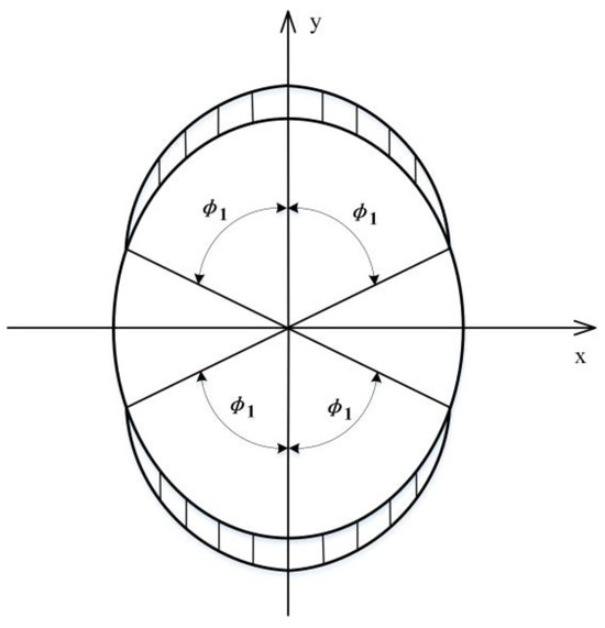
Figure 1.
FB load range schematic.
The number of stress cycles in the outer raceway is:
Substituting Equations (21)–(24) into (20) yields:
In Equations (25) and (26), subscript indicates the inner ring and subscript the outer ring. According to bearing geometry, the following can be obtained:
The upper symbols in the above formula refer to the inner ring and the lower symbols to the outer ring. For ball bearing, the coefficient of curvature radius of raceway (CCRR) is usually used to describe the degree of close contact between the rolling elements and the raceway:
Substituting Equations (25)–(28) into (19) yields the formula for calculating the RREL of the inner ring:
The formula for calculating the RREL of the outer ring is:
Equations (29) and (30), for the material coefficient, for CRB steel, a large number of experiments to derive , for the CCRR of inner ring, for the CCRR of outer ring.
2.3. Calculation of EREL of Bearing Collars
In the previous derivation of the RREL of bearing collars, it is assumed that the REL is uniformly distributed, however, during the operation of FB, the distribution of REL is uneven. In order to calculate the life of collars, it is necessary to introduce the concept of EREL. If the life of the collar is the same under the assumption that the uniformly distributed REL and the actual load distribution have the same mechanical effect, this assumed uniformly distributed REL is called the equivalent rolling element load (EREL) and is noted as .
As mentioned above, the inner ring rotates relative to the direction of the load, and experience has shown that the EREL on the inner ring of a CRB is:
The EREL on the outer ring of a CRB is:
In Equations (31) and (32), is the maximum REL of the bearing under the action of radial load , is the load distribution range parameter (LDRP), is the integral of the EREL of the inner ring, and is the integral of the EREL of the outer ring, which can be obtained from the load distribution:
In Equation (35):
According to the deformation coordination conditions, under the action of radial load , on the basis of geometric relationship, the contact deformation between the rolling element and the raceway in any position can be obtained:
where is the normal clearance between rolling elements and the raceway before the load is applied, is the relative displacement between the inner and outer ring and is the maximum displacement of the inner and outer ring along the direction of force while the radial load applied, at the limit position of the REL distribution range, , the LDRP can be obtained according to Equation (37):
The operation characteristics of FB are different from those of CRB. The radial load applied to the FB is not only related to the deformation force of FS, but also related to the meshing force of HD. In the operation of HD, part of the meshing force is borne by the FS, and the other part of the force is transmitted to the WG. Therefore, the unilateral radial load acting on the FB of the WG is:
where is the force required for FS deformation, the value of about 10% [2] of the nominal torque , is the output torque, is the diameter of FS indexing circle, to the HD with double-wave WG, , is the pressure angle of FS, takes the standard value of , substituting into Equation (39):
By substituting Equation (35), Equation (40) into Equation (31) and Equation (32), respectively, the ERELs of the inner and outer rings of FB can be obtained as:
2.4. Calculation of FB Life
To substituting the EREL for the REL in Equation (18), the life of bearing collars can be obtained while load applied to FB:
The life of the inner and outer rings can be figured out by substituting Equations (28), (29), (41) and (42) into Equation (43), respectively.
3. Modeling
3.1. Calculation and Design of IFB
Selected the CFB [5] FB812 as a design example, the basic parameters are shown in Table 1. IFB is based on the CFB, the outer diameter remains unchanged, increase the inner diameter, the diameter of the rolling elements and the radius of curvature of the collar groove is also smaller, the number of balls may also change, in order to meet the overall structural strength, according to the above related formulas deduced for FB, the calculation and analysis for the radius of curvature of the collar groove, the diameter and the number of the balls has been carried out.

Table 1.
Basic parameters of the CFB FB812.
As the outer diameter of the IFB remains unchanged relative to the CFB, the inner diameter increases, which brings the direct effect that the diameter of the balls will become smaller. According to the fit and geometric relationship between the parts of the bearing, the formula for calculating the diameter of the rolling element can be derived as follows:
where, for the inner ring thickness, for the outer ring thickness, for the inner ring groove depth, for the outer ring groove depth, in accordance with the current design specification of the CFB, for IFB, the inner and outer ring thickness is equal, and the inner and outer ring groove depth is also equal, the calculation formula is as follows:
The radial clearance value of the IFB can be designed according to the specification in the literature [5], the diameter of the rolling element is calculated from Equation (44). The initial contact angle is taken , the radial clearance is taken as: mm, the inner and outer ring thickness is taken mm, the inner and outer ring groove depths are taken , to substitute above parameters into Equation (44) yields mm. Groove depth mm, to take , , the CRR of inner ring mm, the CRR of outer ring mm, the number of balls loaded in the half circle of the FB is about 7. The REL distribution range angle , the LDRP from Equation (38), then to substitute into Equations (33) and (34) yields , , and to substitute into Equation (36) yields .
3.2. Calculation of IFB Life
3.2.1. Calculations Related to RREL
To substitute the parameters of CFB in Table 1 into Equations (29) and (30) yields the RREL of the inner and outer rings, and the RREL of the IFB can be calculated by the same means, the comparison of the results of two FBs is listed in Table 2.
Table 2.
RREL of CFB and IFB.
According to the comparison in Table 2, it can be found that the reduction of the rolling element diameter of the FB will obviously lead to the reduction of the RREL of the bearing. In order to improve the overall performance of the bearing, the parameters of the IFB need to be optimized.
Through Equations (29) and (30), it can be found that the RREL of the FB collars is related to the CCRR and the number of rolling elements. Taking the IFB as an example, the relationship curves between the RREL and the CCRR are calculated, as shown in Figure 2.
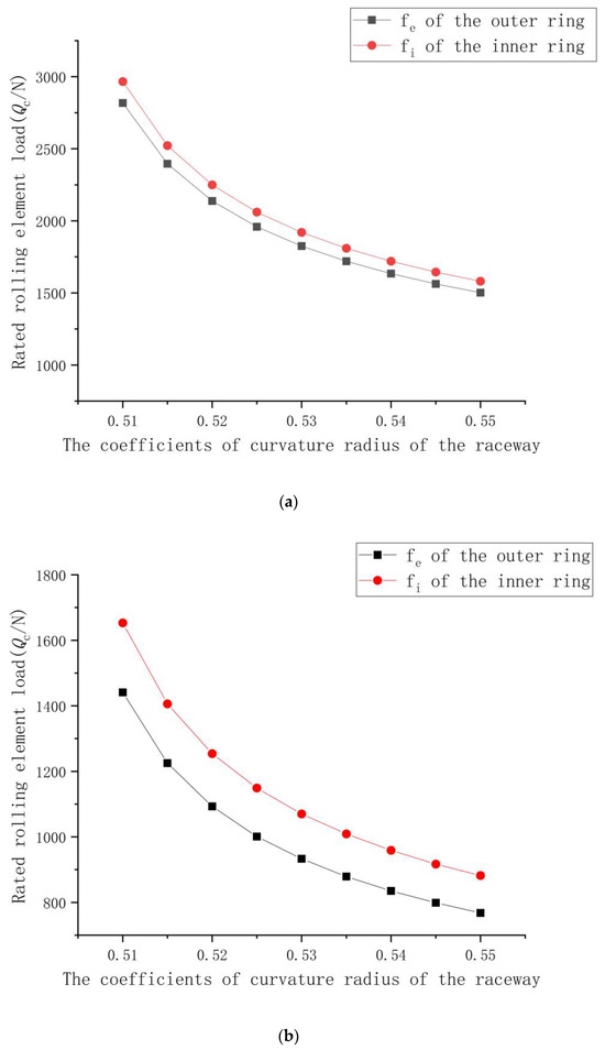
Figure 2.
Relationship between RREL and CCRR: (a) Relationship between the RREL and the CCRR for CFB. (b) Relationship between the RREL and the CCRR for IFB.
According to Figure 2, it can be found that the larger the CCRR of the FB, the smaller the RREL of the collar, while other parameters remain unchanged. The effect on the RREL of the FB can be balanced by reducing the CCRR. The relationship curve between the RREL and the number of rolling elements of the bearing is calculated according to Equations (29) and (30), as shown in Figure 3.
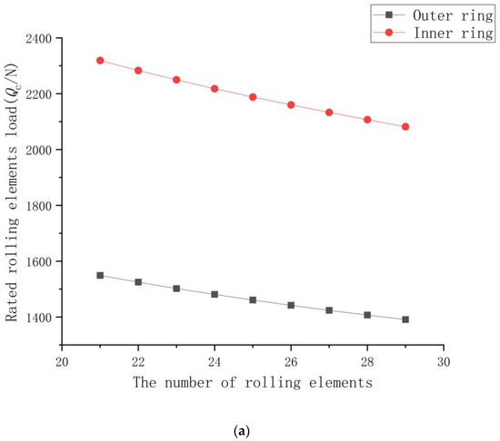
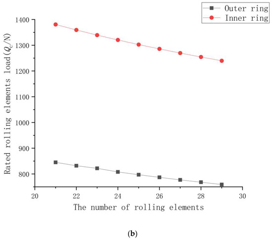
Figure 3.
Relationship between RREL and number of rolling elements: (a) Relationship between the RREL and the number of rolling elements for CFB. (b) Relationship between the RREL and the number of rolling elements in IFB.
According to Figure 3, it can be found that the more the number of balls of the FB, the smaller the RREL of the collar, when other parameters are unchanged. When the outer diameter remains unchanged and the inner diameter increases, the number of rolling elements needs to be increased to ensure the overall performance and load carrying capacity of the FB, but it will lead to a decrease in the RREL, which needs to be balanced by adjusting other parameters.
3.2.2. Calculation of EREL
According to Equations (41) and (42), when the number of rolling elements and the CCRR of the IFB remain unchanged, the EREL of the FB is inversely proportional to the number of balls, i.e., the more the number of rolling elements, the smaller the EREL of the FB, while other parameters remain unchanged. The limit speed of the CFB is 3000 rpm, the maximum torque is 125 N·m, and the indexing circle diameter of the FS is 82.210 mm. Substituting the parameters of the CFB given in Table 1 into Equations (41) and (42), respectively, yield that the EREL of the inner ring 93.324 N and the EREL of the outer ring 99.082 N.
3.2.3. Life Calculation and Parameter Optimization
According to Equations (41) and (42), when the number of rolling elements and the curvature radius coefficient of the raceway of the improved flexible bearing remain unchanged, the EREL of the IFB is equal to that of the CFB. The life of the two FBs before optimization for the number of rolling elements and CCRR can be obtained by substituting the results of the above calculations into Equation (43), which is listed in Table 3.
Table 3.
Fatigue life of inner and outer rings of IFB and CFB before optimization.
Table 3 shows that the life of the IFB will be significantly reduced when it is designed in accordance with the parameters of the CFB (under the conditions of the outer diameter remaining unchanged and the inner diameter increasing). It is necessary to improve the design parameters mentioned above. The life of inner ring is much higher than the life of outer ring of FB. This is due to the fact that the inner ring raceway mainly suffers fluctuating contact stress while the deformation shape remains unchanged; the fatigue damage of the inner ring is mainly caused by the contact stress. The outer ring raceway suffers hertzian stress and bending deformation simultaneously; the stress condition is worse than that of the inner ring. Therefore, the life of the outer ring is lower than that of the inner ring, and the calculation results are consistent with the results in the actual engineering process.
3.3. Parameter Design of IFB
3.3.1. Determination of the Number of Rolling Bodies
To the IFB, the relationship between the number of rolling elements and bearing life can be calculated according to Equations (29), (30) and (41)–(43), and the results are shown in Figure 4:
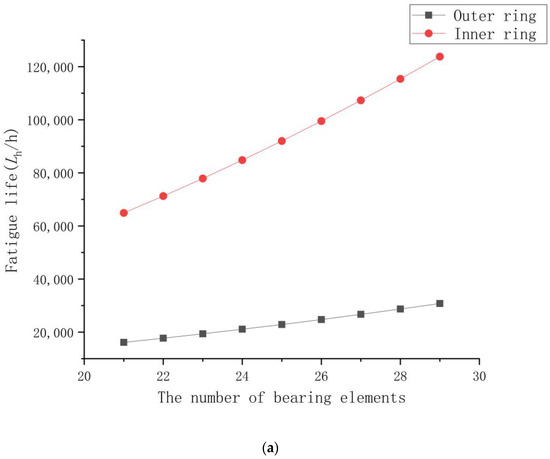
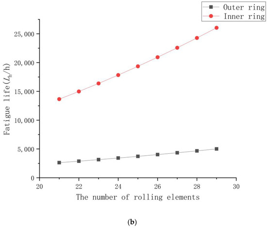
Figure 4.
The relationship between the number of rolling elements and bearing life: (a) Relationship between the number of rolling elements and bearing life of CFB. (b) Relationship between the number of rolling elements and bearing life of IFB.
As shown in Figure 4, while other parameters remain unchanged, the more rolling elements in the FB, the longer fatigue life. The function of the cage in a FB is to isolate and guide the rolling elements and to constrain them in the bearing. Geometrically, as shown in Figure 5, the minimum distance between two rolling elements is calculated as follows:
where is the minimum distance, the of the CFB mentioned above is 2.438 mm by substituting the parameters into Equation (46), and if the remains unchanged, the number of rolling elements of the IFB rounded to 28 according to Equation (46).
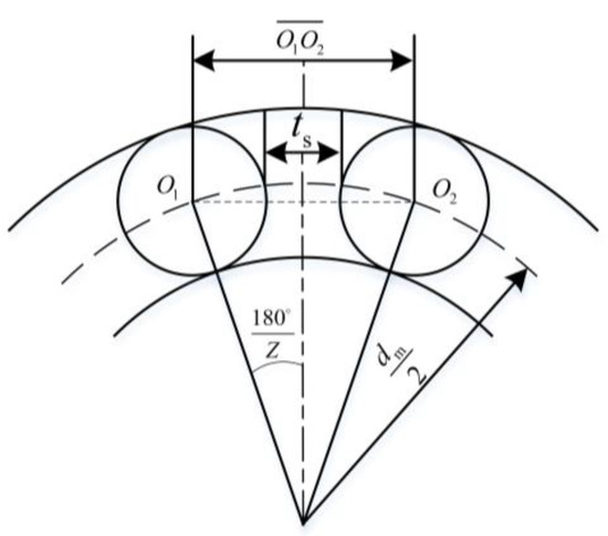
Figure 5.
Schematic diagram for the minimum distance between rolling elements for FB.
From the point of view of bearing fatigue life and geometry, the load capacity of a bearing is closely related to the number of rolling elements; the more rolling elements, the stronger the load capacity of the bearing.
3.3.2. Determination of CCRR
Under the condition of meeting the installation conditions, the number of balls in the following design is taken as 28. According to Equations (29), (30) and (41)–(43) the relationship between the CCRR of the FB and the fatigue life can be calculated, as shown in Figure 6:
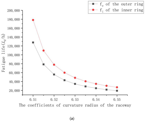
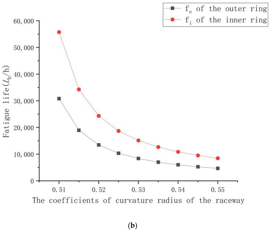
Figure 6.
Relationship between CCRR and bearing life: (a) Relationship between CCRR and bearing life for CFB. (b) Relationship between CCRR and bearing life of IFB.
As shown in Figure 6, the smaller the CCRR of the FB, the longer the fatigue life obtained. However, the curvature radius of the raceway is closely related to the axial load carrying capacity of the FB. The CCRR of the inner ring of CFB is between 0.515 and 0.525, and the CCRR of the outer ring is between 0.53 and 0.55 [5], in which the fatigue life of the inner ring of the IFB can reach more than 10,000 h so the CCRR of inner ring can be kept unchanged. The following is intended to improve the CCRR of the outer ring of the IFB from the perspective of the axial load capacity of the bearing. The contact point between the rolling elements and the collar is at the most edge state of the raceway. The axial load in this state is called the ultimate axial load, and the safe contact angle under the ultimate axial load is calculated as follows [37]:
where is the included angle between the connection line and bearing radial plane, the connection line linked the bearing outer ring raceway shoulder edge and rolling elements center of the line and between the angle, with related constants, can be obtained by looking up the table, for the initial contact angle of the bearing, for the safety of the bearing contact angle, and for the elastic deformation constants:
is the total curvature radius coefficient:
The safe contact angle of the FB can be calculated by iterative method according to Equation (46), and the ultimate axial load is calculated as follows:
In Equation (50), is the acceleration of gravity. Equation (50) shows that the ultimate axial load of the FB is directly proportional to the number of rolling elements. Substituting the parameters of CFB into Equation (50) yields the ultimate axial load of 1035 N approximately. This is according to the geometric relationship, taking the number of rolling elements of the FB as 28 and CCRR of the IFB as 0.52, and by substituting above parameter into Equation (50) to carry out the calculation of the ultimate axial load of the FB with different CCRR, as shown in Figure 7:
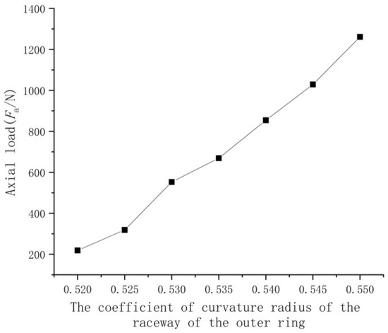
Figure 7.
The relationship between axial load and the CCRR of outer ring.
As shown in Figure 7, the larger the CCRR of the outer ring in FB, the stronger the axial load carrying capacity of the bearing. In summary, following the aforementioned method, the basic parameters such as the diameter and the number of rolling elements, the coefficient of curvature radius of the raceways of the outer inner ring, and the outer ring in FB can be determined. For example, the basic parameters of the CFB and the IFB of type FB812 are listed in Table 4. Under the condition of limiting speed of 3000 rpm, the fatigue life of the IFB can reach over 8000 h.
Table 4.
The basic parameters of CFB and IFB.
3.3.3. Calculation of The Moment of Inertia
To the IFB, the inner diameter, the number and the diameter of rolling elements of IFB have changed, while the outer diameter remains unchanged. The difference of rotational speed between the inner and outer rings is significant; the inner ring rotates with the WG, and the outer ring rotates with the FS. The moment of inertia of the standard and IFB of type FB812 is calculated according to the parameters in Table 4, and the results are as follows:
As shown in Table 5, the moment of inertia of the IFB is reduced by about 30% compared with the CFB. For the IFB, the inner diameter and the number of rolling elements increase, and the diameter of rolling elements decrease. The overall moment of inertia of the flexible decreases, so the diameter of the rolling elements has a greater impact on the moment of inertia of the FB.
Table 5.
The moment of inertia of CFB and IFB.
4. Simulation and Experimental Results
4.1. Finite Element Modeling
As shown in Table 4, the 3D model was created using SOLIDWORKS 2020, for the convenience of calculation; the model does not contain the cage part, the inner and outer rings are not chamfered, and the whole model structure is divided into four parts: the outer ring of the FB, the inner ring, the rolling element, and the cam. After the modeling is completed, and to import the model into ABAQUS 2020 for assembly, the material properties of each component is determined according to Table 6.
Table 6.
FB material parameters for each component.
The C3D8R hexahedral unit is used to mesh the parts, and the rolling elements and the inner and outer ring contact parts are mesh encrypted, the mesh model is shown in Figure 8.
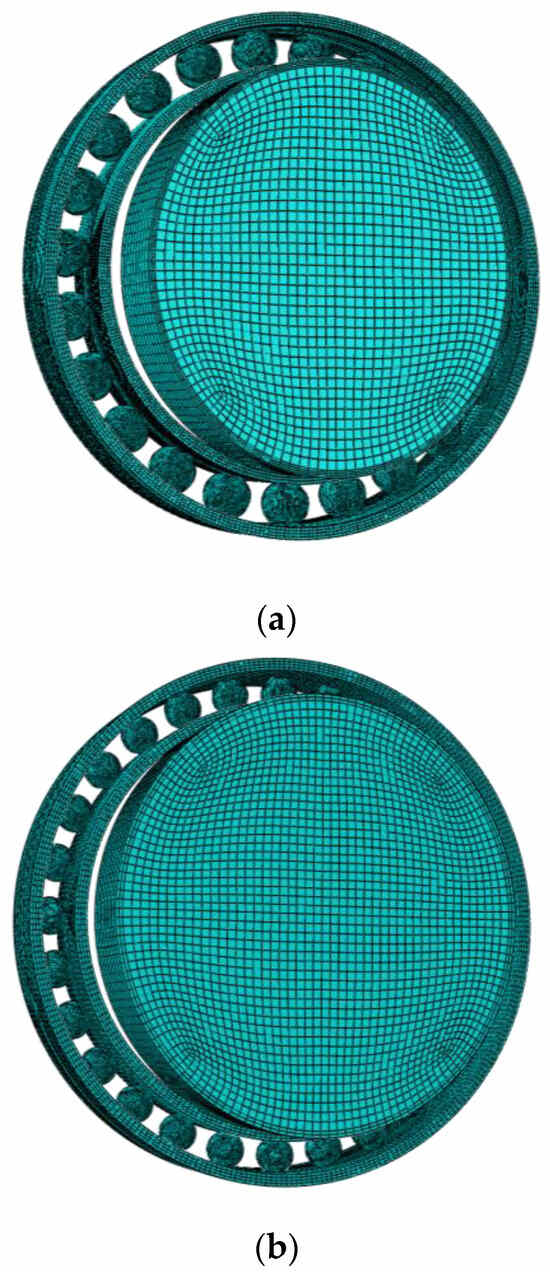
Figure 8.
FB finite element modeling: (a) CFB finite element model. (b) IFB finite element modeling.
4.2. Loads and Boundary Conditions
To simulate the actual loading situation of the FB under cam assembly, the cam is pressed into the inner ring of the FB and the FB is forced to deform. It is necessary to define the frictional contact between the rolling element and the inner ring, and the frictional contact between the outer surface of the cam and the inner surface of the inner ring. The normal contact stiffness is set to 0.1, and the initial proximity factor is set to 0.1. When the cam is loaded, the rotation of the inner ring, the outer ring, and the translational degree of freedom in the Z direction are, respectively, constrained. The rolling element can rotate when the cam is installed, so it is necessary to constrain the rotational freedom of the rolling element. For the convenience of convergence, the cam is set as a rigid element, and a displacement load is given so that it is completely pressed into the FB. The stress and strain on the FB is analyzed after deformation is completed.
4.3. Analysis of Results
In this paper, the length of the long semi-major axis of the cam is 0.5 mm longer than the radius of the inner ring of the FB. When the cam is fully pressed into the FB, the deformation of the FB is shown in Figure 9 and Figure 10.
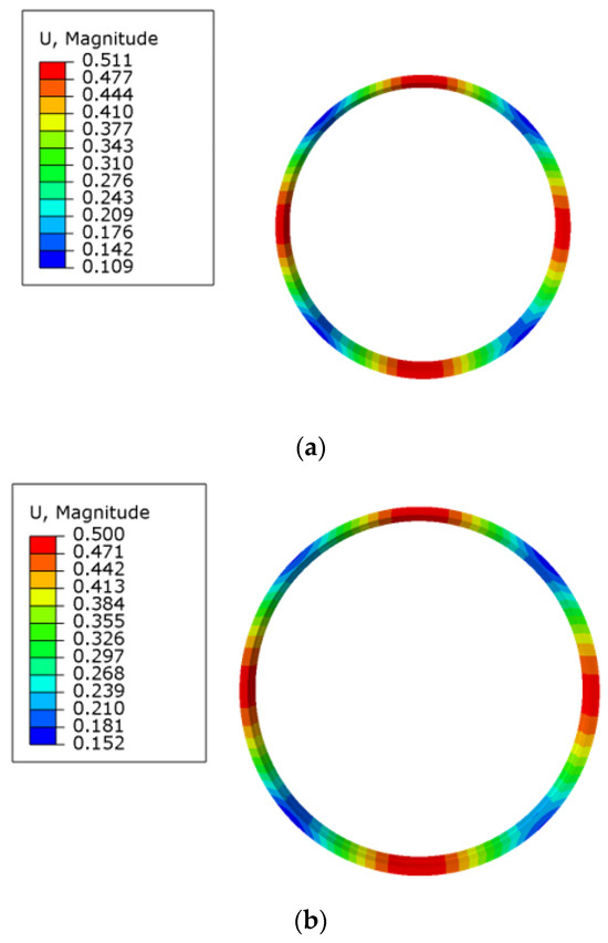
Figure 9.
Deformation diagram of a CFB assembled with a cam: (a) Deformation diagram of FB inner ring. (b) Deformation diagram FB outer ring.
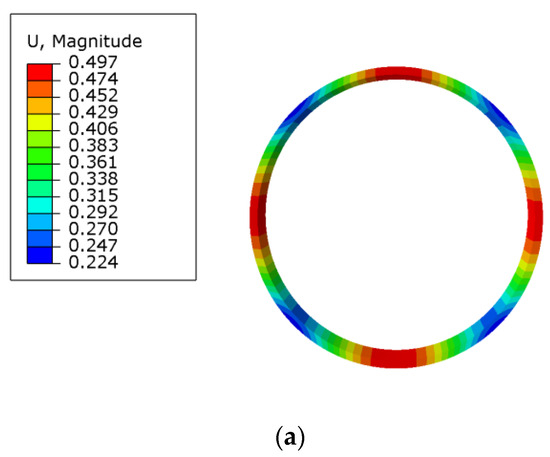
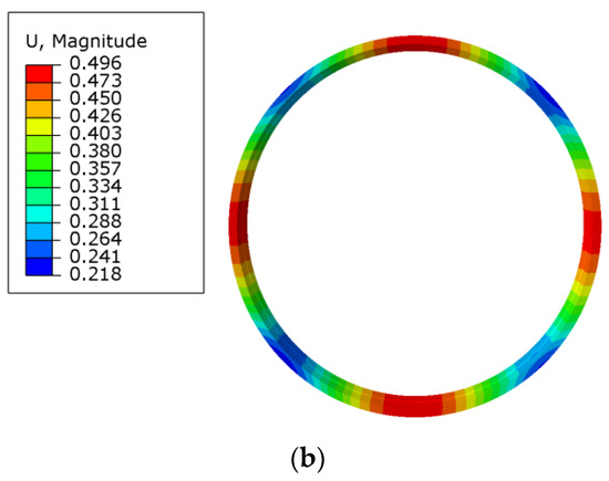
Figure 10.
Deformation diagram of IFB with cam assembly: (a) Deformation diagram of FB inner ring. (b) Deformation diagram FB outer ring.
Figure 9 and Figure 10 show that the significant deformation of the inner and outer rings is mainly concentrated in the long axis and short axis directions of the cam while the assembling and loading of FB completed. The maximum deformation is located in the direction of the major axis of the cam, and the maximum displacement in the direction of the minor axis is smaller than that in the direction of the major axis. In addition, the inner ring suffers the force from the cam and produce significant deformation, the outer ring is deformed by REL, and the maximum displacement of the inner ring of the FB is basically the same as the outer ring. Under the action of a cam assembly with the same radial displacement deformation, the displacement of the IFB is basically the same as that of the CFB.
The results of stress analysis are shown in Figure 11 and Figure 12, the equivalent stress on the inner and outer rings of the flexible bearing is concentrated at the positions of the long and short axis of the cam, and the maximum equivalent stress is at the contact point between the rolling element and the inner and outer raceways in the major axis direction of the cam.
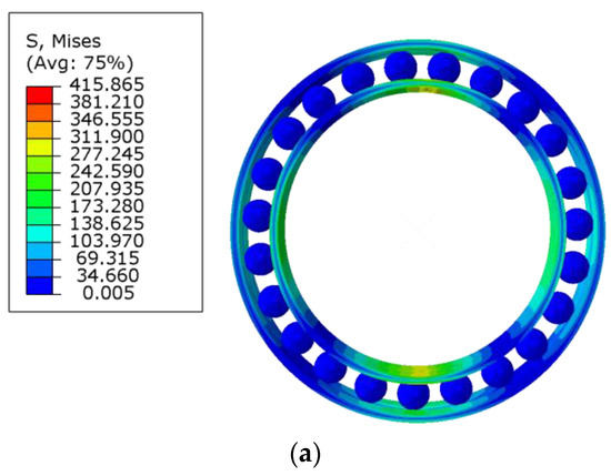
Figure 11.
Deformation diagram of a CFB assembled with a cam: (a) FB overall stress diagram. (b) Stress diagram of FB inner ring. (c) Stress diagram of FB outer ring.
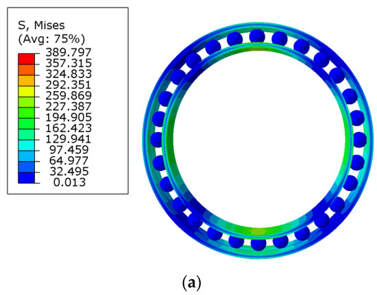
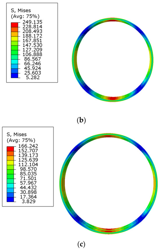
Figure 12.
Deformation diagram of IFB with cam WG assembly: (a) FB overall stress diagram. (b) Stress diagram of FB inner ring. (c) Stress diagram of FB outer ring.
The inner ring rotates with the WG driven by actuator during the operation of FB, the outer ring rotates very slowly and is generally assumed to be stationary. To further optimize the design of the IFB, the width of the inner ring is reduced for the purpose to reduce the moment of inertia of FB. The width of the inner ring FB is reduced by 1 mm on both sides, respectively, and the model is established while FEA is carried out on it. The results are shown in Figure 13:
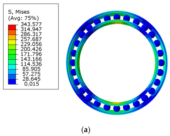
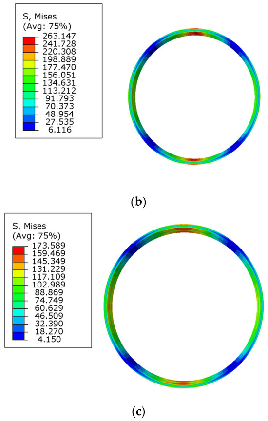
Figure 13.
Stress analysis diagram for FB with narrow inner ring: (a) FB overall stress diagram. (b) Stress diagram of FB inner ring. (c) Stress diagram of FB outer ring.
Summarizing the above finite element analysis results, the maximum equivalent stresses of the FB rings are listed in Table 7.
Table 7.
Maximum equivalent force of FB rings.
5. Discussion
The load distribution of FB is not the same as that of CRB. The FB is subjected to two-sided forces at the major axis of cam assembly, and the number of stress cycles is twice as much as that of CRB. The formula for the RREL of FB is derived from the actual stress situation of FB in this paper. The load acting on the FB is related to the deformation force and engagement force of the FS. The radial force on the FB is transmitted by the radial component of the torque of the FS, and the formula of EREL is derived according to the force characteristics of the FB so as to deduce the new design formula of FB.
The fatigue life of CFB under rated test conditions is about 10,000 h. Using the new design formula to calculate the existing CFB, the results are in good agreement with the actual test results. That verifies the accuracy and effectiveness of the new design formula and provides a theoretical basis for the improvement of the design of FB.
In order to meet the requirements of FB with larger inner diameter, it is necessary to improve the structural parameters of existing CFB. The diameter of the rolling elements of FB decreases while keeping the outer diameter constant and the inner diameter increasing. According to the empirical formula of CFB, when the CCRR is constant, the CRR of the IFB becomes smaller. When the number of rolling elements remains unchanged, the distance between the centers of the two rolling elements increases (i.e., the thickness of the separate block of the cage also increases).
Calculations of IFB are carried out by means of new design formulas derived for the improved design of CFB, and the changes in geometrical parameters have a great influence on the load distribution and life of FB, which includes the following: the decrease of rolling element diameter leads to the decrease of the RREL of the FB collar, which results in a sharp decrease in the overall fatigue life of the FB. The effect of CCRR on the lifespan and axial bearing capacity of IFB and CFB is consistent. The decrease in the CRR leads to the decrease in the ultimate axial load. The new design formula shows that the decreasing the CCRR increases the RREL of the collar, and increasing the number of rolling elements result in the increase of the RREL of the collar and decrease of the EREL of the collar at the same time. In order to ensure the load carrying capacity of FB and improve the RREL of the collar, so as to improve the fatigue life of FB, methods to increase the number of rolling elements and reduce the radius of curvature coefficient are necessary. The calculation and optimization have been performed to the parameters determination of IFB on the basis of new design formula of FB. The calculation results show that to increase the number of rolling elements and reduce the CCRR within a certain range will improve the capacity and fatigue life and reduce the moment of inertia of FB when the diameter of the rolling element is reduced. Taking into account the stress characteristics and fatigue life of FB and the CCRR of inner and outer rings, the diameter and number of rolling elements of IFB is determined.
The FEA results have shown that in the case of the same displacement of deformation, the maximum equivalent force of the IFB collar is smaller than that of the CFB, which is due to the fact that the number of rolling elements of the IFB is more than CFB, improving the load carrying capacity of the IFB. While decreasing the CCRR of IFB collar, the deformation generated at the contact between the rolling elements and raceway has a certain effect on the ellipse contact, and reducing the width of the inner ring increases the maximum equivalent force of the FB. The material selected for the FB collar is GCr15, and the yield limit is about 518.42 MPa. According to the FEA results, it can be found that the maximum equivalent force of the CFB and the IFB are all less than the yield limit, and the material can meet the performance requirements.
6. Conclusions
On the basis of the theory of CRB, and considering the operation characteristics of FB in HD, by using the first method of L-P theory this paper deduces the new formula for the FB fatigue life and proposes a new method for the design of structure parameters of FB. On this basis, the novel design method for IFB with a larger inner diameter compared to CFB is proposed, and an improved design instance is made for a type of CFB.
The finite element model of the FB is established by ABAQUS 2020, and the mechanical analysis of the FB is carried out: The equivalent force of FB is concentrated in the major and minor shaft directions of cam WG, and the equivalent force in the major shaft direction is greater. Under the action of the cam WG assembly with the same displacement of deformation, the displacement of the IFB is basically the same as that of the CFB. The maximum equivalent force of the IFB collar is smaller than that of the CFB. The maximum equivalent force of FB is related to the number of rolling elements and the CRR. Increasing the number of rolling elements and reducing the CCRR results in the reduction of the maximum equivalent force of FB, improving the bearing capacity. While the width of the outer ring of the FB remains unchanged and the width of the inner ring decreases, the maximum equivalent force of the inner and outer rings will increase.
Author Contributions
Conceptualization, H.X. and F.H.; methodology, H.X. and F.H.; software, F.H.; formal analysis, F.H. and H.X.; investigation, F.H. and H.X.; resources, H.X.; data curation, F.H.; writing—original draft preparation, F.H.; writing—review and editing, H.X. and F.H.; visualization, F.H. and H.X.; project administration, H.X.; funding acquisition, H.X. All authors have read and agreed to the published version of the manuscript.
Funding
This research was funded by the Key Project of the Science and Technology Plan Project of Beijing Municipal Education Commission (KZ201210011012).
Institutional Review Board Statement
Not applicable.
Informed Consent Statement
Not applicable.
Data Availability Statement
The data presented in this study are available on request from the corresponding author. The data are not publicly available due to laboratory policy.
Conflicts of Interest
The authors declare no conflict of interest.
References
- Xin, H. Current status and trend of domestic and international development of harmonic drive. Maschinen Mark 2009, 35, 8–10. [Google Scholar]
- Shen, Y.; Ye, Q. Theory and Design of Harmonic Drive; China Machine Press: Beijing, China, 1985; pp. 289–294. [Google Scholar]
- Ren, D. Life calculation of flexible bearing in harmonic drives. Mach. Des. Res. 1990, 4, 30–31. [Google Scholar]
- Li, Y. The optimization calculation method of rolling bearing life. China South Agric. Mach. 2020, 51, 207–208. [Google Scholar]
- Ivanov, M.N. The Harmonic Drive; National Defense Industry Press: Beijing, China, 1987. [Google Scholar]
- Wang, J.; Xu, H. Load Sequence and Life Analysis of Deep Groove Ball Bearing. J. Mech. Eng. 2017, 53, 131–140. [Google Scholar] [CrossRef]
- Yang, Y.; Zeng, X.; Shi, Y.; Lei, Y.; Zeng, F. The influence of flexible bearing design parameters on the fatigue life of the soft wheel of harmonic reducer. Mech. Electr. Inf. 2020, 17, 53–55. [Google Scholar]
- Guan, C. Calculation for The Contact Pressure of Flexible Bearings Under Dynamic Load. J. Northeast China Heavy Mach. Inst. 1994, 3, 220–226. [Google Scholar]
- Li, L. Static and Dynamic Analysis of Flexspline and Flexible Bearing under the Cam with Typical Profile. Master’s Thesis, Harbin Institute of Technology, Harbin, China, 2016. [Google Scholar]
- Mahanto, B.S.; Sahoo, V.; Maiti, R. Effect of cam insertion on stresses in harmonic drive in industrial robotic joints. Procedia Comput. Sci. 2018, 133, 432–439. [Google Scholar] [CrossRef]
- Liu, Z. Analysing Stress of Flexible Bearing under Harmonic Gear Drive. J. Dalian Univ. 1995, 4, 512–517. [Google Scholar]
- Hao, F.; Wen, S. Internal load analysis of flexible bearing for harmonic drives. Mach. Des. Manuf. 1991, 1, 34–37. [Google Scholar]
- You, B.; Wen, J. Load distribution calculation of flexible ball bearing with elliptical cam wave generator. In Proceedings of the 2016 International Conference on Mechanics, Materials and Structural Engineering, Jeju Island, Republic of Korea, 18–20 March 2016. [Google Scholar]
- Weinzapfel, N.; Sadeghi, F. A Discrete Element Approach for Modeling Cage Flexibility in Ball Bearing Dynamics Simulations. J. Tribol. 2009, 131, 021102. [Google Scholar] [CrossRef]
- Wang, A.; Wang, Y.; Zhao, K.; Song, L. Mechanical calculation on the flexible bearing of harmonic driver. IOP Conf. Ser. Mater. Sci. Eng. 2019, 490, 052032. [Google Scholar] [CrossRef]
- Jiang, Y.; Wang, Y.; Tong, Q. Theoretical Calculation and Simulation Analysis of Internal Load Distribution of Flexible Bearing in Harmonic Drive. Mach. Des. Res. 2017, 3, 91–94. [Google Scholar]
- Zhao, D. Parameterized Design and Finite Element Analysis for Roller Bearings. Master’s Thesis, Shandong University of Science and Technology, Qingdao, China, 2008. [Google Scholar]
- Yu, G.; Huang, M.; Wang, X.; Shen, J.; Nie, Z. Effects of Structural Parameters of Inner and Outer Rings on Stress of Flexible Bearings. Bearing 2016, 8, 9–12. [Google Scholar]
- Xiang, X.; Zhang, W.; Wang, X.; Yu, G.; Dong, J.; Zhang, J. Stress Characteristics’ Analysis of Flexible Bearings at Different Speeds. Metrol. Meas. Tech. 2017, 4, 6–8. [Google Scholar]
- Adams, C.; Skowronek, A.; Bös, J.; Melz, T. Vibrations of elliptically shaped bearings in strain wave gearings. J. Vib. Acoust. 2016, 138, 021004. [Google Scholar] [CrossRef]
- Zhu, C.Z.; Wang, X.J.; Li, Z.L.; Liu, J.; Zheng, J. Research on static and dynamics mechanical characteristics of flexible bearing in harmonic reducer. Int. J. Adv. Robot. Syst. 2020, 17, 1729881420919953. [Google Scholar]
- Ostapski, W.; Mukha, I. Stress state analysis of harmonic drive elements by FEM. Bull. Pol. Acad. Sci. Tech. Sci. 2007, 55, 115–123. [Google Scholar]
- Pan, X.; Dong, S.; Mu, S.; Zhao, X. Research on load distribution and fatigue life of flexible bearings in harmonic drive after assembly deformation. J. Mech. Strength 2020, 2, 453–458. [Google Scholar]
- Zhao, D.; Wang, Y.; Zhao, K. Simulation Analysis on Fatigue Life of Flexible Bearings Based on Dynamics. Bearings 2019, 7, 20–23. [Google Scholar]
- Qin, Y.; Wang, C.; Guo, L.; Fu, L. Development of Testing Machine for Flexible Bearings for Harmonic Drive Gear Reducers of Industrial Robots. Mech. Electr. Eng. Technol. 2020, 11, 158–160. [Google Scholar]
- Xin, H.; Cao, Z.; Zhang, W.; Zhang, F.; Liu, L. Design of fatigue life testing machine for flexible bearing in harmonic drive. Mod. Manuf. Eng. 2020, 4, 123–125. [Google Scholar]
- Zhang, Y. Cam Wave Generator-Flexible Bearing Parametric Design and Mechanical Analysis. Master’s Thesis, Kunming University of Science and Technology, Kunming, China, 2022. [Google Scholar]
- Liu, B.; Tao, M.; Mu, M.; Chen, D.; Wu, C.; Wu, J.; Zhang, H.; Shu, W. Analysis on Fatigue Life and Mechanical Characteristics of Flexible Bearings of Harmonic Reducers. J. Mech. Transm. 2023, 47, 131–136. [Google Scholar]
- Wang, p.; Zhao, C.; Li, J.; Zhou, Z.; Yan, H.; Hu, J. Meshing Characteristics and Stress Deformation Analysis on Harmonic Reducer. Aeronaut. Sci. Technol. 2023, 34, 73–80. [Google Scholar]
- Mu, X.; Shao, Z.; Hao, C.; Gao, M.; Zhang, C. Fracture Analysis on Flexspline and Flexible Bearing of the Harmonic Reducer. J. Mech. Transm. 2023, 47, 100–104. [Google Scholar]
- Wang, Y. Accelerated Test and Life Prediction Analysis of Harmonic Reducer. Master’s Thesis, Shanghai Jiao Tong University, Shanghai, China, 2021. [Google Scholar]
- Pastukhov, A.; Timashov, E.; Stanojević, D. Temperature Conditions and Diagnostics of Bearings. Appl. Eng. Lett. 2023, 8, 45–51. [Google Scholar] [CrossRef]
- Desnica, E.; Ašonja, A.; Radovanović, L.; Palinkaš, I.; Kiss, I. Selection, Dimensioning and Maintenance of Roller Bearings. In Proceedings of the International Conference on Organization and Technology of Maintenance, Osijek, Croatia, 30 November 2022. [Google Scholar]
- Yang, G.; Zhong, Y.; Yang, L.; Tao, H.; Li, J.; Du, R. Fault diagnosis of harmonic drive with imbalanced data using generative adversarial network. IEEE Trans. Instrum. Meas. 2021, 70, 3519911. [Google Scholar] [CrossRef]
- Large Hollow Speed Reducer Unit FBS-2UH Series. Available online: https://www.hds.co.jp/english/products/news/newproduct/backnumber.html?ItemId=211&dispmid=1699 (accessed on 10 November 2022).
- Jia, H.; Xin, H. Study on lubrication characteristics of novel forced wave generator of harmonic drive without flexible bearing. Materials 2021, 15, 215. [Google Scholar] [CrossRef] [PubMed]
- Deng, S.; Jia, Q. Rolling Bearing Design Principles, 2nd ed.; Standards Press of China: Beijing, China, 2014. [Google Scholar]
Disclaimer/Publisher’s Note: The statements, opinions and data contained in all publications are solely those of the individual author(s) and contributor(s) and not of MDPI and/or the editor(s). MDPI and/or the editor(s) disclaim responsibility for any injury to people or property resulting from any ideas, methods, instructions or products referred to in the content. |
© 2023 by the authors. Licensee MDPI, Basel, Switzerland. This article is an open access article distributed under the terms and conditions of the Creative Commons Attribution (CC BY) license (https://creativecommons.org/licenses/by/4.0/).