Article

Control Design for Soft Transition for Landing Preparation of Light Compound-Wing Unmanned Aerial Vehicles Based on Incremental Nonlinear Dynamic Inversion

1
College of Aerospace Engineering, Nanjing University of Aeronautics and Astronautics, Nanjing 210016, China
2
Key Laboratory of Unsteady Aerodynamics and Flow Control, Ministry of Industry and Information Technology, College of Aerospace Engineering, Nanjing University of Aeronautics and Astronautics, Nanjing 210016, China
*
Author to whom correspondence should be addressed.
Appl. Sci. 2023, 13(22), 12225; https://doi.org/10.3390/app132212225
Submission received: 17 October 2023 / Revised: 1 November 2023 / Accepted: 8 November 2023 / Published: 10 November 2023
(This article belongs to the Section Aerospace Science and Engineering)

Abstract

:
This paper proposes a soft switching mode for electric vertical takeoff and landing (eVTOL) compound-wing unmanned aerial vehicles (UAVs) to achieve a smooth transition between modes. The proposed mode pre-compensates the lift loss with the rotary wing during the deceleration stage before UAV landing. The control law adopted in this paper consists of implicit nonlinear dynamic inversion (NDI) and incremental nonlinear dynamic inversion (INDI). The outer loop (attitude angle loop) control law is based on implicit NDI, while the inner loop (attitude angle rate loop) controller is based on INDI. An extended state observer (ESO) is employed to estimate the angular acceleration. This paper innovates by proposing a soft switching strategy that improves the robustness, safety, and smoothness of the transition for the compound-wing UAV, and applying advanced control law to mode transition design. For the future application of eVTOL aircraft in UAM scenarios, this paper evaluates the smoothness of transition and passenger comfort using normal overload as a physical quantity. The Monte Carlo (MC) simulation results demonstrate that the proposed mode can reduce the peak normal overload by about 89%.

1. Introduction

Emerging eVTOL aircraft is becoming a hot topic for aerospace engineers due to the concept of urban air mobility (UAM) [1].
As the battery energy density increases and the battery technology continues to optimize and develop [2,3], the improvements in rechargeable batteries make various electric UAM aircraft designs possible. According to calculation by Sripad et al. [4], different UAM aircraft consume 130 Wh to 1200 Wh per passenger per mile, depending on the design and utilization, while terrestrial electric vehicles and combustion engine vehicles are expected to consume more than 220 Wh and 1000 Wh per passenger per mile, respectively. They also found that, based on the specific power and energy of lithium-ion batteries, various UAM aircraft designs are close to technological feasibility.
As populations become concentrated in cities, traffic congestions worsen, and UAM is considered as a potential solution. Therefore, many institutions and companies around the world are developing UAM vehicles, building infrastructure, and researching flight operating systems [5]. At the same time, the flight experience of passengers also becomes an important aspect of the design and operation of eVTOL aircraft. For example, a study by Thomas et al. [6] shows that perceived safety, noise and vibration, availability and access, passenger well-being, concern for the environment, and vehicle motion are the six aspects that passengers care about the most, and they need to be highlighted and addressed well in the design.
Meanwhile, compound aircrafts are attracting a lot of attention in both academic and industrial fields because of the performance constraints of conventional helicopters and planes. A compound-wing UAV is a VTOL aircraft that combines fixed wings and rotary wings, also known as fixed-wing hybrid UAVs [7]. A compound-wing configuration eVTOL aircraft uses completely independent thrusters (non-vector thrust) for cruise and lift, relies on the wing to provide cruise lift [8], and uses innovative powerplants and aerodynamic designs to achieve the VTOL capability of rotors and the speed/altitude performance of planes [9]. Fixed-wing UAVs have advantages such as large flight speed, high flight altitude, long flight duration, and high fuel efficiency. Rotary-wing UAVs have features such as vertical takeoff and landing, hover capability, and flexibility, making them applicable in various scenarios. Compound-wing UAVs boast the advantages of fixed-wing UAVs and rotary-wing UAVs, show the characteristics of safety, cost-effectiveness, environmental friendliness, flexibility, diversity, etc. [10], and are suitable for a wide range of applications such as urban, suburban, and long-distance tasks [11]. The characteristics of the compound-wing UAVs determine that this type of aircraft has a wide range of applications, such as being highly utilized in a wide range of services such as photography, path planning, search and rescue, power line inspection and civil construction [12].

1.1. Transition Phase for Compound-Wing UAVs

The flight process of compound-wing UAVs can be divided into vertical takeoff and landing state, cruising state, and transition state. For compound-wing and other VTOL aircraft, the transition phase is a stage of changing the flight mode, such as the compound-wing aircraft switching from fixed-wing mode to rotor mode when decelerating to stall speed, which can achieve subsequent short-distance/vertical landing, and the tilt-rotor aircraft placing the tilt-rotor horizontally after accelerating to stall speed, etc. [13].
Due to the reduction in flight speed of electric vertical takeoff and landing aircraft in the deceleration transition phase, the aerodynamic force gradually weakens, resulting in lift loss, dynamic stability reduction, and aerodynamic control surface efficiency decline. In addition, the transition phase of the compound-wing aircraft is a complex process [14] involving significant nonlinear characteristics and complex aerodynamic characteristics, and is difficult to control, making it a critical and dangerous stage throughout the entire flight process. Therefore, more stringent requirements are put forward for the control law, which become the key and challenging aspect in the design of UAV control law.
Yang et al. [15] pointed out in their study that autonomous transition control of V/STOL aircraft is an important challenge, different from general flight control problems. Transition control is a nonlinear, nonaffine control problem, and attitude and position movements are affected during the transition process, so the flight path must be controlled well. In addition, the transition phase is a multi-input problem with special inputs.
Yuksek et al. demonstrated in their research on the transition phase of fixed-wing VTOL UAVs that the transition flight phase should be carefully planned, not only for stable operation, but also for safe transition between flight modes in urban airspace. They also proposed a design of the flight control system to compensate for the aerodynamic effects during the transition phase [16].
Therefore, when designing the transition stage of the compound-wing unmanned aircraft, safety must be given a higher priority. For this, we consider trading time and energy for higher safety, and use simulations to verify the rationality and necessity of this approach.

1.2. Implicit NDI, INDI

A team from Delft University in the Netherlands has conducted extensive design research on nonlinear dynamic inversion (NDI) control, a method that uses “inversion” of a dynamic system to design feedback linearization for general nonlinear control systems. For example, Juliana et al. [17] designed a controller using a feedback control algorithm combining classical proportional integral (PI) and proportional differential (PD) techniques through NDI to eliminate the nonlinear effects caused by uncertainty in the closed-loop system.
Chen et al. [18] design a transition period control method for a thrust vectoring vertical/short takeoff and landing (STOVL) UAV, that uses implicit NDI for the outer loop control circuit and improved eigenstructure assignment for the inner loop. They design guidance laws by converting the trajectory deviation into attitude control commands, and the guidance commands are tracked and the attitude is stabilized. The full six-degree-of-freedom (six-DOF) flight simulation results show that after the deceleration transition speed is lower than the minimum level flight speed, the UAV still maintains good trajectory tracking and attitude stability. Therefore, in eVTOL control design, converting the trajectory deviation into attitude control commands is also an important part, which can be accomplished by using the implicit NDI method. This is the reason why we choose implicit NDI as the outer loop control law in the transition phase control design.
Sieberling et al. [19] from Delft University proposed an improved method called incremental nonlinear dynamic inversion (INDI) control. Unlike NDI, INDI incorporates incremental control [20], and shows better robustness [21,22] and anti-interference ability [23] in flight control. One major advantage of INDI is that it only requires a small portion of the model and does not rely on the inputs required by the control system. Additionally, INDI can handle model uncertainty better, showing robustness in the presence of inaccurate models without complex control structures or adaptive components [24]. Incremental nonlinear dynamic inversion control has been applied in eVTOL aircraft, achieving precise tracking of attitude commands [25], and its robustness has been also validated [26,27].
Simplício et al. [28] simplified the design of helicopter flight controllers using a new approach based on INDI. By using feedback based on acceleration measurements, it avoided depending on information related to any changes in aerodynamic characteristics, and the control system did not require any model data that relied entirely on their state variables, thereby enhancing its robustness to inaccurate models. The test result shows that the controller stabilized the system and tracked the desired ground speed according to the specified performance characteristics. Therefore, INDI control can handle nonlinear models while providing robustness in the presence of model uncertainty without complex control structures or adaptive components.
Mokhtari et al. [29] proposed a disturbance observer and demonstrated the good performance and stability of the closed-loop system. They pointed out that designing a nonlinear observer to estimate the unknown state is a means to solve the lack of sensor information. Therefore, this paper adopts an observer in the control law design to observe the information missing from the sensors.
Lyu et al. [30] proposed a new framework for supersonic roll maneuver control that combines INDI and extended state observer (ESO). ESO reduces command oscillations and improves the servo’s working life. Their proposed control achieves high-precision tracking performance during rapid roll maneuvers. Furthermore, the effectiveness and robustness of the controller were demonstrated through Monte Carlo (MC) simulation and frequency domain analysis. Therefore, the combined INDI and ESO controller may perform better in extreme application scenarios of highly nonlinear models, and this is the reason why we choose INDI+ESO as the inner loop control law in the transition phase control design.
This work is organized as follows:
  • A 6-DOF modeling and platform introduction for the prototype VtolA7.
  • Design of guidance and control architecture for the longitudinal channels.
  • The transition strategy design for landing preparation and MC simulations for robustness verification.
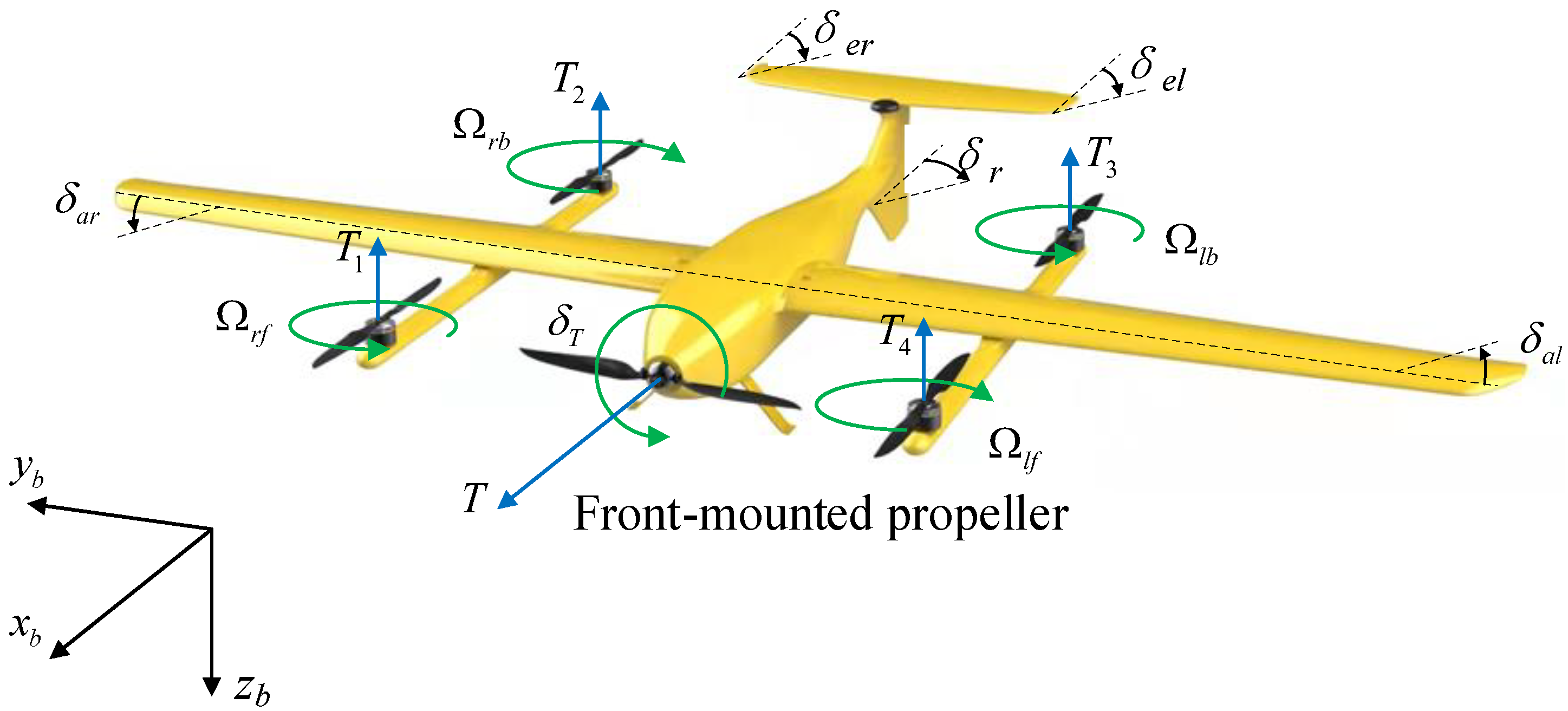
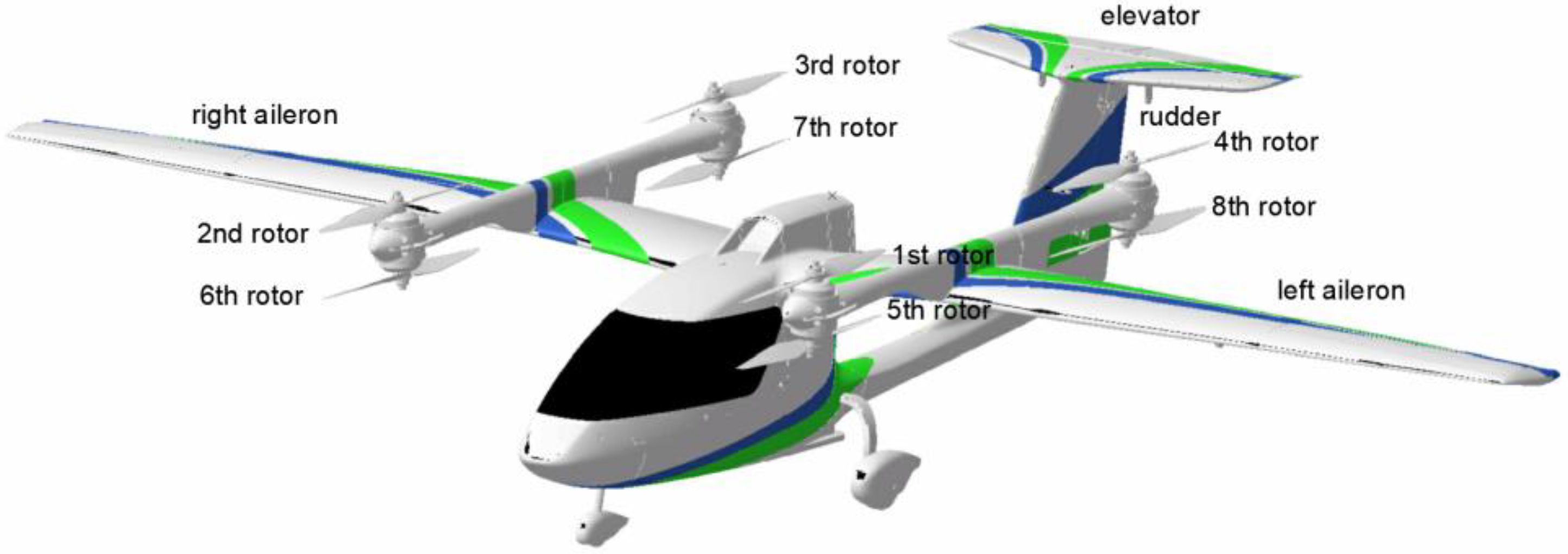
2. The UAV VtolA7

2.1. Platform Design and Operating Principle

The UAV VtolA7 shown in Figure 1, which is the subject of this study, is a lightweight compound-wing drone with eVTOL characteristics. It can be used as a test aircraft for validating control design, as well as a probe for future UAM vehicles. For example, it has a similar layout to the existing UAM vehicle ET120 (shown in Figure 2) [31], and can be used as a low-cost method for validation.
As a compound-wing UAV, VtolA7 has conventional fixed-wing surfaces (ailerons, elevators, rudder), a front-mounted propeller, and a group of four vertical rotors arranged in an X pattern. Table 1 shows its general properties.
The VtolA7 has two power systems: the hover power system and the propulsion power system. The hover system is powered by four rotor motors attached vertically on the wings. The propulsion system consists only of a single propeller mounted horizontally in front of the nacelle to provide cruise power. The VtolA7 has two attitude control systems: a fixed-wing and a rotary-wing system. The fixed-wing system consists of three conventional fixed-wing rudder surfaces: the aileron, the elevator, and the rudder. The rotary-wing system can achieve attitude control through differential speed of the four rotors. Figure 3 shows its control mechanism.

2.2. Aircraft Dynamics Modeling

2.2.1. Aerodynamic Model

The forces acting on the aircraft are the lift, drag, and side force, and the moments are, respectively, roll, pitch, and yaw moment.
L = 0.5 C L ρ V t 2 S D = 0.5 C D ρ V t 2 S Y = 0.5 C Y ρ V t 2 S l a = 0.5 C l ρ V t 2 S b m a = 0.5 C m ρ V t 2 S c n a = 0.5 C n ρ V t 2 S b
where ρ is the atmospheric density; V t is the airspeed; and S , b , and c are, respectively, reference area, reference span, and reference chord length. C L , C D , C Y , C l , C m , C n are the respective aerodynamic coefficients.

2.2.2. Six-DOF Equation

Convert the aerodynamic force L , D , Y from the wind coordinate system to the body coordinate system:
F x = D cos α cos β Y cos α sin β + L sin α G sin θ + T F y = D sin β + Y cos β + G sin ϕ cos θ F z = D sin α cos β sin α sin β L cos α + G cos ϕ cos θ k = 1 4 T k
Among the above equations, α and β are, respectively, the angle of attack and sideslip angle of VtolA7. The resultant moment acting on VtolA7 can be expressed as:
l = l a i = 1 4 T k ( y k y c g ) + Q T m = m a + m c g + k = 1 4 T k ( x k x c g ) + k = 1 4 M y k n = n a + n c g + k = 1 4 Q k
where, x k , y k , and z k are, respectively, the coordinates of the k-th rotor in the body coordinate system. l a , m a , n a are, respectively, the aerodynamic moment. x r , y r , z r and y c g , x c g , z c g are, respectively, the aerodynamic reference point and center of gravity the body coordinate system. m c g and n c g are additional changes caused by the inconsistency between the focus and the center of gravity, and the thrust line of the front paddle and the center of gravity. Q T is the reaction torque caused by the front-mounted propeller. Q k is the k-th reaction torque caused by the k-th rotor.
m c g = L cos α + Y sin α sin β + D sin α ( x r x c g ) T 5 ( z 5 z c g ) n c g = ( Y cos β D sin β ) ( x r x c g )
According to Newton’s second law, the translation and rotation equation of six-DOF can be expressed as:
u ˙ = v r w q + F x / m g v ˙ = w p u r + F y / m g w ˙ = u q v p + F z / m g l = I x p ˙ + ( I z I y ) q r I z x ( p q + r ˙ ) m = I x q ˙ + ( I x I z ) r p + I z x ( p 2 r 2 ) n = I x r ˙ + ( I y I x ) p q + I z x ( q r p ˙ )
where, u , v , and w are velocity vectors of the body coordinate system; m g is the mass of the aircraft; I x , I y , and I z are moments of inertia; I x y , I y z , and I z x are products of inertia.
Equations of motion for VtolA7 can be rewritten:
x ˙ g = u cos θ cos ψ + v ( sin θ sin ϕ cos ψ cos ϕ sin ψ ) + w ( sin θ cos ϕ cos ψ + sin ϕ sin ψ ) y ˙ g = u cos θ sin ψ + v ( sin θ sin ϕ sin ψ + cos ϕ cos ψ ) + w ( sin θ cos ϕ sin ψ sin ϕ cos ψ ) h ˙ = u sin θ v sin ϕ cos θ w cos ϕ sin θ ϕ ˙ = p + tan θ ( q sin ϕ + r cos ϕ ) θ ˙ = q cos ϕ r sin ϕ ψ ˙ = ( q sin ϕ + r cos ϕ ) / cos θ
where, x g , y g , and h are the position of the aircraft in the inertial system, ϕ , θ , and ψ are, respectively, the roll, pitch, and yaw angles.

3. Control Design for Transition Phase

The control design fir the transition phase is divided into two parts: guidance law and control law, as shown in Figure 4

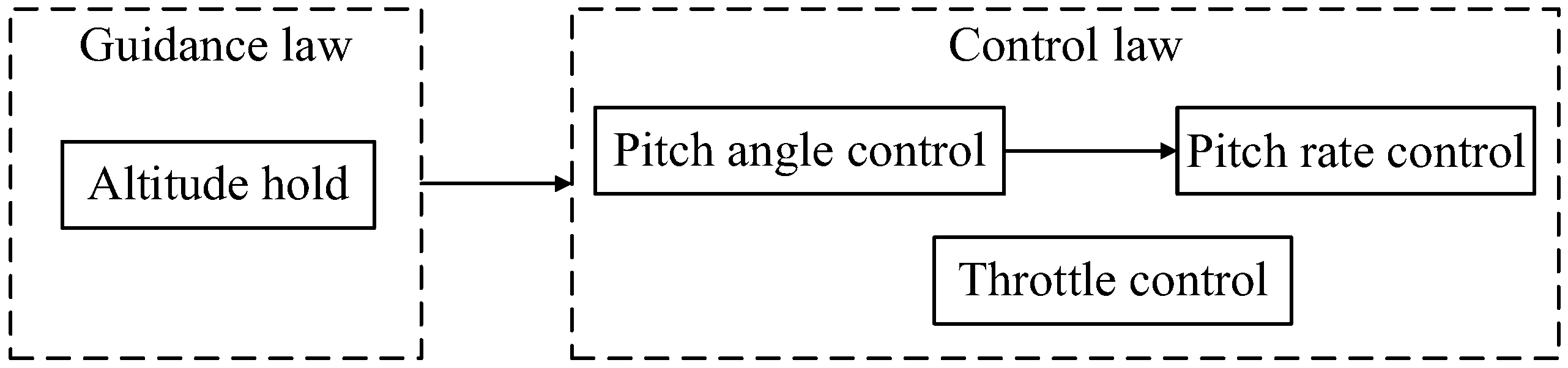
3.1. Guidance Law Design

To realize the switching design of the transition phase, the guidance law adopts the altitude hold mode to realize altitude tracking.

3.1.1. Altitude— θ Channel

This channel is used for the fixed-wing mode, which controls the altitude by adjusting the pitch angle command to achieve the altitude hold function. Figure 5 shows its geometric principles through a diagram. The guidance law design is introduced as follows.
The difference between the desired altitude and the current absolute altitude is calculated using Equation (7) to obtain the altitude error; the altitude error is then used in Equation (8) to generate the climb rate command; the climb rate command is converted into the flight path angle command using Equation (9); and the pitch angle command is obtained using Equation (10). The pitch angle command is fed into the outer loop pitch attitude control law to maintain the climb rate. Moreover, the climb rate and the normal load factor are also limited. Therefore, the altitude tracking is realized by transforming the altitude command into the pitch angle command.
Δ H = h c h
h ˙ c = k Δ H
γ c = arctan ( h ˙ c v g )
θ c = k γ ( s + Z α ) s γ c

3.1.2. Altitude— Ω h e a v e Channel

This channel is used for the rotary-wing mode, which controls the altitude by varying the lift force by changing the speed of the four rotors to achieve the altitude hold function. The guidance law design is explained as follows.
The difference between the desired altitude and the current absolute altitude is obtained using Equation (7) to get the altitude error; the altitude error is then used in Equation (8) to generate the climb rate command, and then the climb rate command is converted into the rotary-wing mode hover command Ω h e a v e ; the hover command is distributed to each rotor to realize the altitude tracking.

3.2. Control Law Design

The transition phase control of VtolA7 is a longitudinal channel control problem. The longitudinal channel control equation is given by Equation (11):
d x d t = x ˙ = Δ V ˙ Δ α ˙ Δ q ˙ Δ θ ˙ = X V X α + g 0 g Z V Z α 1 0 M ¯ V M ¯ α ˙ Z V M ¯ α M ¯ α ˙ Z a M ¯ q M ¯ α ˙ 0 0 0 1 0 Δ V Δ α Δ q Δ θ + X δ e X δ T Z δ e Z δ T M ¯ δ e M ¯ α ˙ Z δ e M ¯ δ p M ¯ α ˙ Z δ T 0 0 Δ δ e Δ δ T = Ax + Bu
where the state vector x = Δ V Δ α Δ q Δ θ T , the control vector u = Δ δ e Δ δ T T . Δ δ T and Δ δ e are, respectively, elevator deflection angle and throttle lever position.

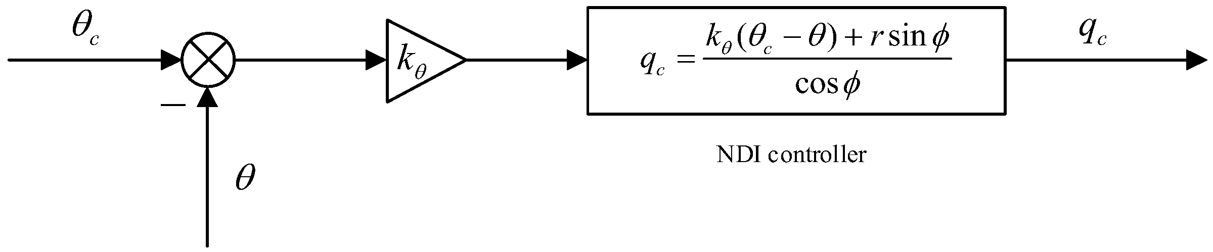
3.2.1. Pitch Angle Control

The pitch angle control structure adopts the pitch rate control as the inner loop, and the outer loop is designed using the dynamic inversion control method, which enables the pitch command to track the pitch rate command accurately. Figure 6 shows its control structure. The dynamic equation of the pitch angle is given by:
θ ˙ = q cos ϕ r sin ϕ
θ ˙ can be regarded as the desired change rate of the pitch angle. The NDI controller ensures that the pitch rate controller can track the commands quickly without steady-state errors in the presence of model uncertainty and external bounded unsteady disturbances. In order to ensure that the pitch angle can track the commands rapidly, the pitch angle control adopts the proportional control structure, and the pitch angle rate is expressed as:
θ ˙ = k θ ( θ c θ )
where k θ is the bandwidth of pitch angle control loop. Substitute Equation (13) into Equation (12):
k θ ( θ c θ ) = q cos ϕ r sin ϕ
The rolling angle is limited within −1~1 rad, and the control law of the pitch angle loop can be obtained using Equation (14):
q c = k θ ( θ c θ ) + r sin ϕ cos ϕ
where, θ c is the pitch angle command, θ is the pitch angle feedback value, ϕ is the roll angle, r is the yaw angle rate, and q c is the pitch angle rate command generated by the pitch angle loop.

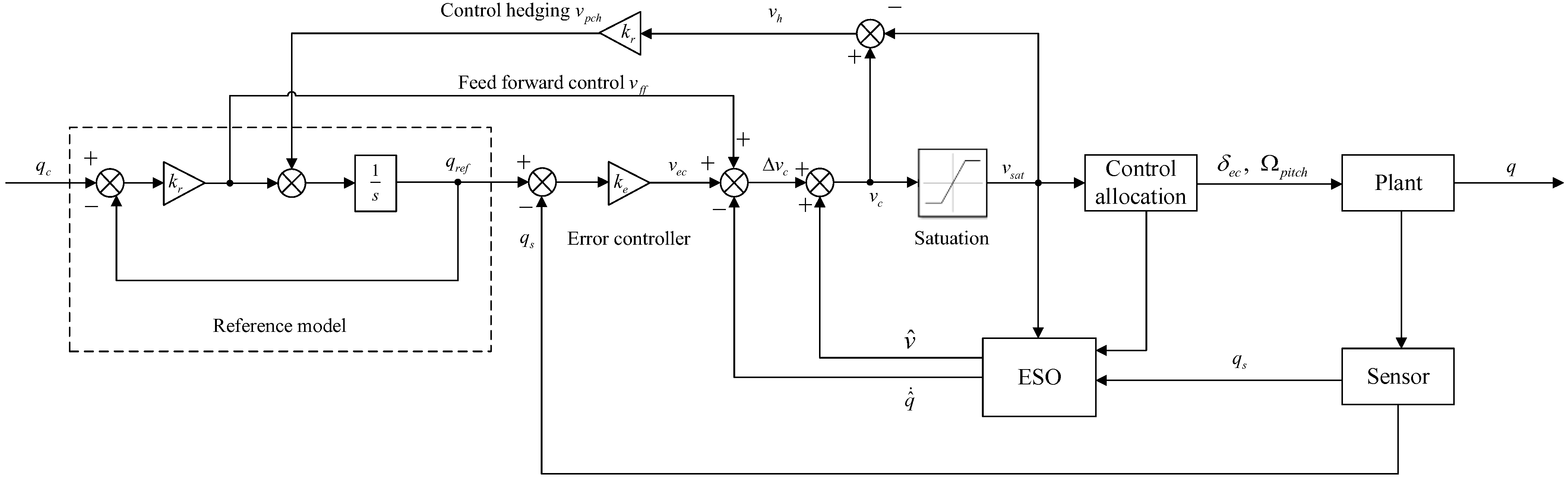
3.2.2. Pitch Angle Rate Control

The pitch angle rate loop is responsible for controlling the pitch angular rates, as the main control objectives. It is controlled using INDI+ESO [30]. The overall control structure is shown in Figure 7.
The control structure consists of four key components: reference model, error controller, ESO, and control allocation.
The gain in the control law can be determined by adjusting parameters, which requires sufficient experimentation and iteration. We chose to fine tune based on previous relevant research [30] and determined that the gains K r , K e , and K h are 7, 70, and 0.11, respectively.
For the control assignment section, how the pitch rate command q ˙ c is assigned to the elevator command δ e c and the rotary-wing pitch command p i t c h is determined by the control strategy which will be explained in Section 3.3.
The structure of ESO is shown in Figure 8.
  • where the on-board model input q ^ ˙ m can be calculated as
    q ^ ˙ m = M ¯ δ e δ e + M ¯ q q s
The gain parameters K P and K I are determined as 4 and 4, also by tuning parameters. The purpose is to enable the ESO to evaluate the angular acceleration of the current timestamp.

3.2.3. Throttle Control

To stabilize and control the airspeed of the UAV, the throttle control design adopts the NDI control design. Figure 9 shows its structure.
The throttle control design adopts the speed hold mode, and the speed control loop outputs the throttle command δ T :
δ T = m T max k i ( ν c ν ) d t k p v
where m is the mass of VtolA7, Tmax is the maximum thrust, k i and k p are throttle controller gains, k i = 0.25 , and k p = 0.8 .

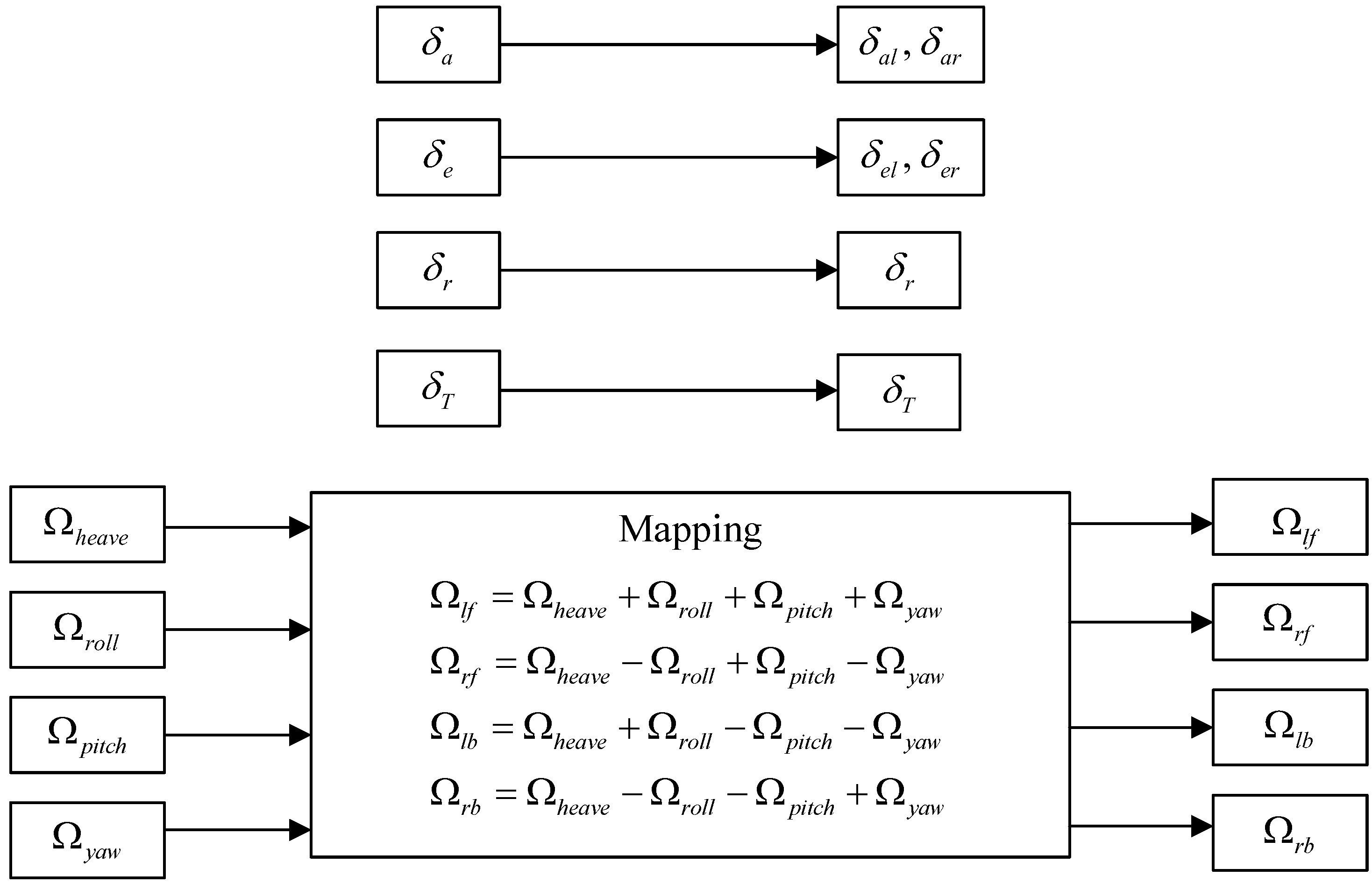
3.2.4. Lateral Directional Channel Control

Because the design of the transition phase mainly focuses on the longitudinal channel and does not require changes in the command of the lateral channel, the lateral design can use the original channel for steady-level flight. This section only provides a brief introduction to the principle of lateral channel control.
The lateral channel implements roll angle rate control. The roll angle adopts implicit NDI control, and the principle is:
p c = k ϕ ( ϕ c ϕ ) tan θ ( q sin ϕ + r cos ϕ )
where ϕ c is the roll angle command and k ϕ is the roll angle control gain.
The roll angle rate is controlled using by INDI, and its control principle is similar to that of the pitch channel, which is not explained further here.
In the fixed-wing mode of the directional channel, yaw damping control is applied, while in the rotary-wing mode, yaw rate control is used to keep the yaw rate command at 0 to ensure directional stability. The yaw rate is controlled using INDI, and its control principle is similar to that of the pitch channel.

3.3. Control Strategy for Soft Transition Design

The three modes of transition phase design are shown in Figure 10, which includes the control logic and control allocation of the entire transition phase.
The control strategy for transition phase is based on:
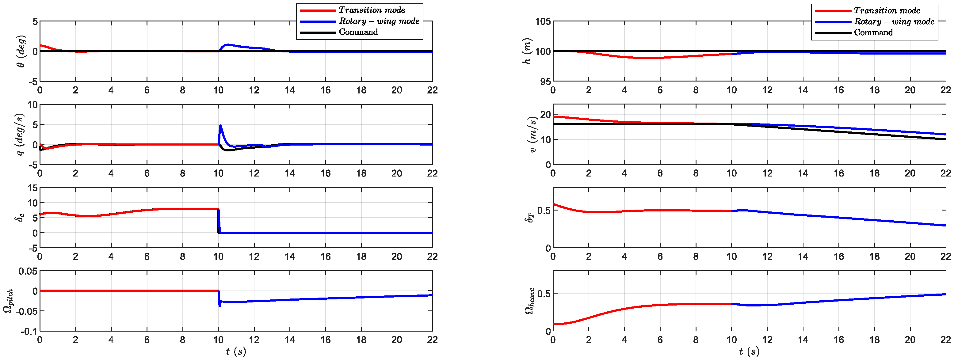
  • For the height-pitch angle-pitch angle-rate loop, before the elevator stops controlling the pitch attitude, it starts the rotors in advance to replace the elevator to follow the commands related to altitude control. After the fixed-wing mode is switched to the switching mode for 10 s (or even shorter, 5 s), the UAV’s flight attitude reaches a stable state, and then switches to the rotary-wing mode so that the elevator is no longer participates in attitude control, thus realizing a smooth transition of mode switching.
  • For the speed loop, during the switching mode, a deceleration signal is given (reducing from the cruise speed to the switching speed) to achieve the deceleration control of the transition phase.
The advantage of the soft transition design is that the mode switching is divided into two steps: in the first step, the rotary wing takes over the height control, and then takes over the attitude angle and attitude angle rate control after it reaches a steady state, so that the abrupt change in flight attitude of the UAV is split into two parts, and the stability and safety of the switching process are improved at the cost of time and energy consumption.
The early start of the rotors, as well as the sudden change in height, speed, angle, and angle rate caused by mode switching, is a disturbance to the control law, which puts forward high requirements on the robustness of the UAV, as well as on the design of the control law and control strategy.

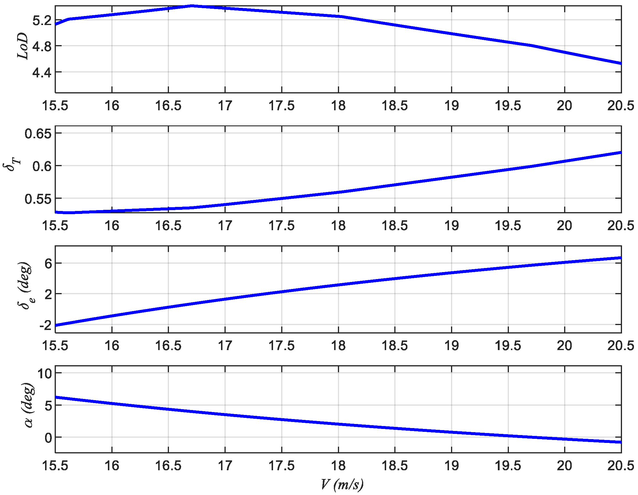
4. Performance Analysis of Deceleration Transition Phase for UAV

To obtain the level flight performance of the UAV in the deceleration transition phase, and to prepare for the subsequent simulation work, it is necessary to perform longitudinal channel trimming of the UAV model. All trim and subsequent simulation work in this article is based on software MATLAB & Simulink 9.5.0.944444 (R2018b). At a cruising altitude of 100 m, from 1 m/s to 30 m/s at intervals of 1 m/s, the longitudinal channel trimming of the fixed-wing mode UAV model is performed, and part of the trimming results are shown in Figure 11.
The selection of cruise speed requires consideration of a higher lift–drag ratio, a lower throttle, a smaller elevator angle, and a smaller pitch angle. Therefore, 19 m/s is chosen as the cruise speed.
To verify the consistency between the trim results and the actual situation of the aircraft, the authors conducted a live flight test and extracted partial live flight data of UAV VtolA7 during the level flight phase, as shown in Figure 12.
During this steady level flight for 20 s, the average values of each parameter are obtained as shown in Table 2. It can be observed that the flight test results are consistent with the trim results. Due to the small impact of altitude factors, it can be considered that the model has high accuracy, and the trim results can serve as a basis for performance analysis of the deceleration transition phase. The selection of a cruising speed of 19 m/s is reasonable.
The level flight speed in the switching mode (referred to as the switching speed) requires consideration of the lower-level flight speed and the efficiency of the elevator. Therefore, 16 m/s is selected as the switching speed.

5. Nominal Simulation and Monte Carlo Shooting Simulation

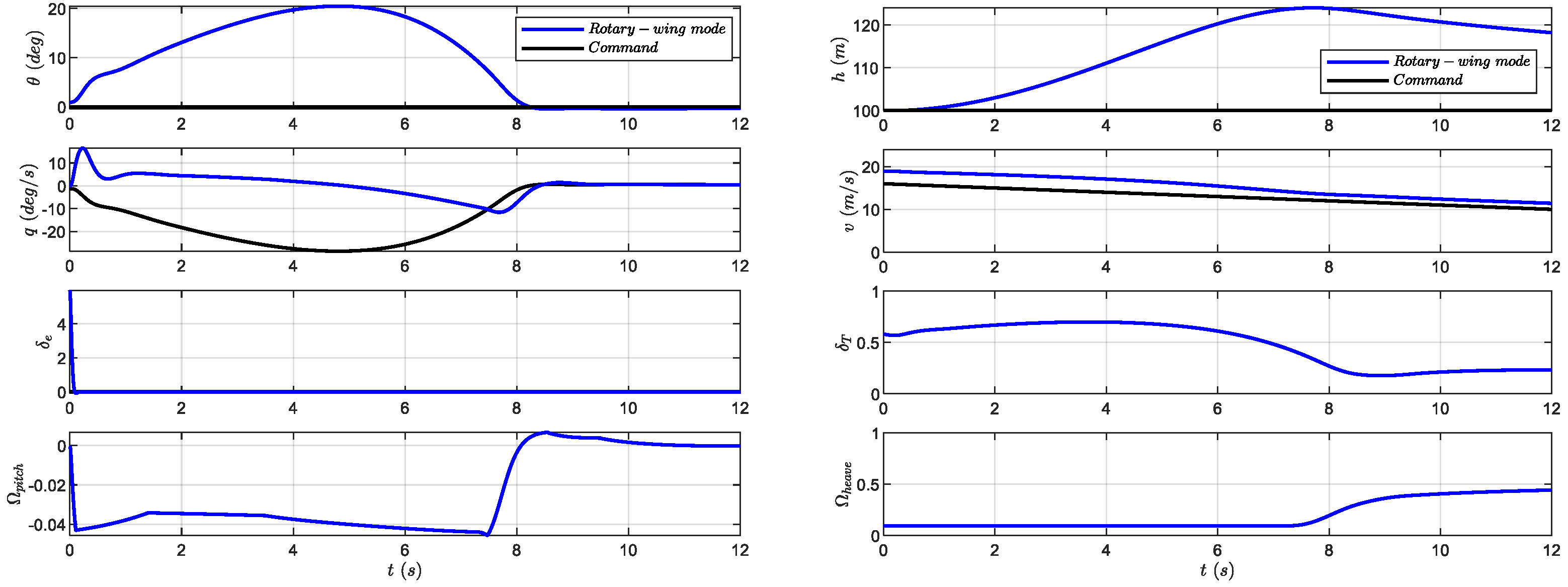
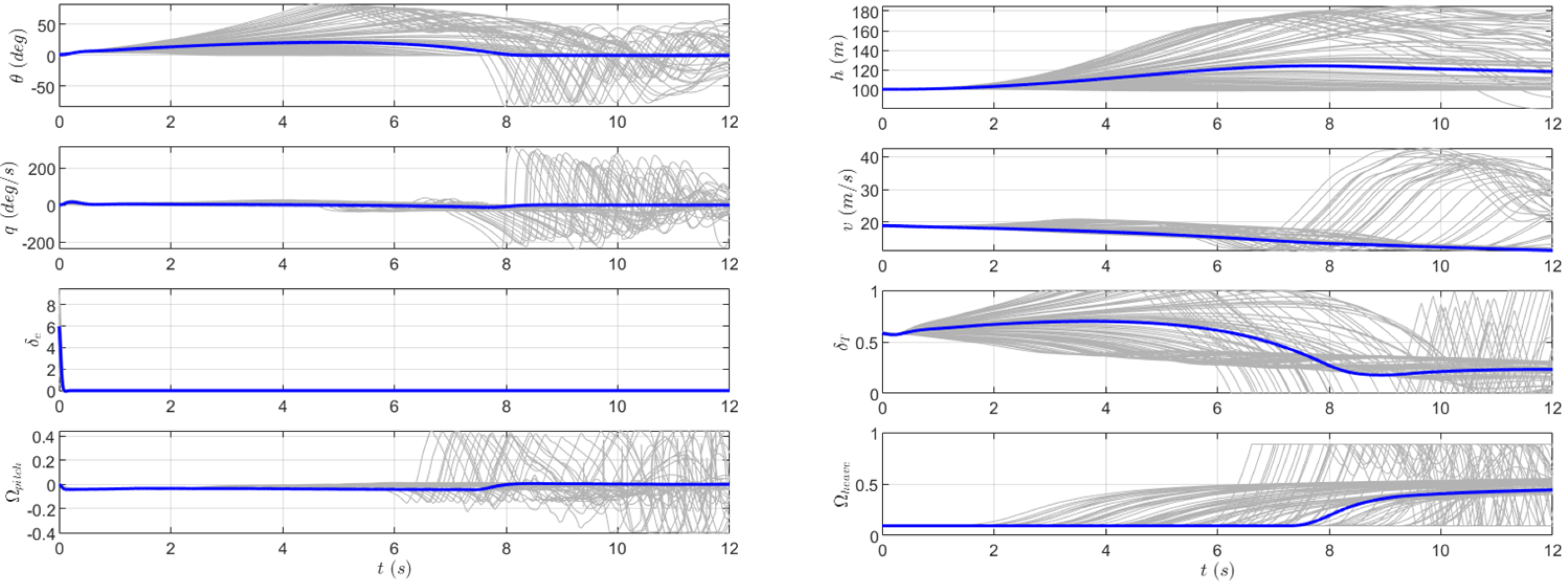
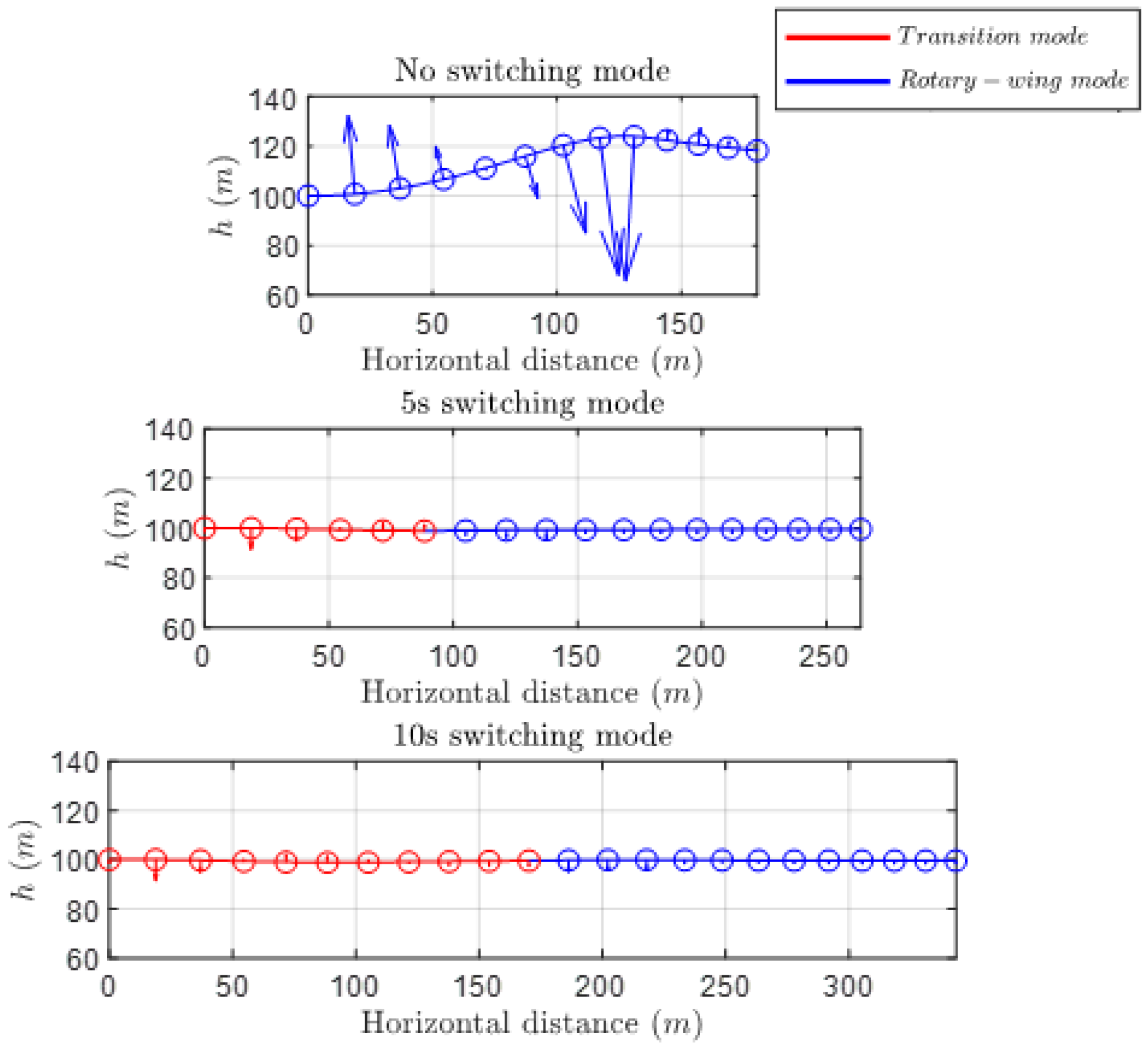
5.1. Simulation of Direct Switching

100 m height, 19 m/s cruise speed, and 16 m/s switching speed are selected as simulation environment to realize the process of switching from fixed-wing mode to switching mode, and from switching mode to rotary-wing mode. The process maintains a fixed height, and the pitch angle command is zero to ensure the smallest possible pitch angle. After switching to the rotary-wing mode, it decelerates and prepares for the subsequent hovering landing.
The nominal simulation of direct transition was conducted first. Direct transition refers to the process of switching from fixed-wing mode to rotary-wing mode without going through the switching mode (that is, reducing the switching mode duration to 0 s) and keeping the fixed height and airspeed command unchanged. Figure 13 displays the simulation results after entering the rotary-wing mode by direct transition.
Here, the commands Ω p i t c h , Ω h e a v e , and δ T are dimensionless: 0 means none and 1 means the full speed of the corresponding rotor/front-mounted propeller, which are 0 RPM and 8000 RPM, respectively.
Although the direct transition from fixed-wing mode to rotary-wing mode can be achieved under the current control framework, there are large fluctuations in pitch angle and altitude in the subsequent rotary-wing mode. It is preliminarily speculated that adverse situations may occur under the influence of model uncertainty, so Monte Carlo (MC) shooting simulation with model uncertainty is needed.
Simple and practical MC shooting simulation is often used to verify the robustness of controllers with model uncertainties. By setting the disturbance range of all model parameters, randomly forming them, and assigning them to the simulation system, it is a direct nonlinear robustness verification method that is suitable for almost all control systems. In order to compare different switching mode designs and prevent a small amount of data from affecting the accuracy of the conclusion in parameter random perturbations, a random number sequence of 100 random numbers is generated, and the subsequent biased simulations use this group of random seeds, which can facilitate the inspection and reproduction of the simulation results, and also compare different transition phase designs under the condition of variable control.
The perturbation ranges of all model parameters of the longitudinal channel designed in this manuscript are shown in Table 3.
The results of 100 times of MC shooting simulations are drawn into images, as shown in Figure 14. For the transition phase without switching mode design, although mode switching is basically realized in the nominal simulation, problems such as pitch angle oscillation and drastic change, loss of altitude maintenance, throttle saturation and rotor speed saturation occurred in all 100 MC target shooting simulations with 20% model uncertainty. Therefore, the transition phase without switching mode may pose a serious threat to flight safety and it is more vulnerable to model uncertainty and shows relatively poor robustness.
Therefore, a soft transition design is needed to address issues caused by mode switching, such as loss of altitude tracking, drastic changes in pitch attitude, and poor robustness.

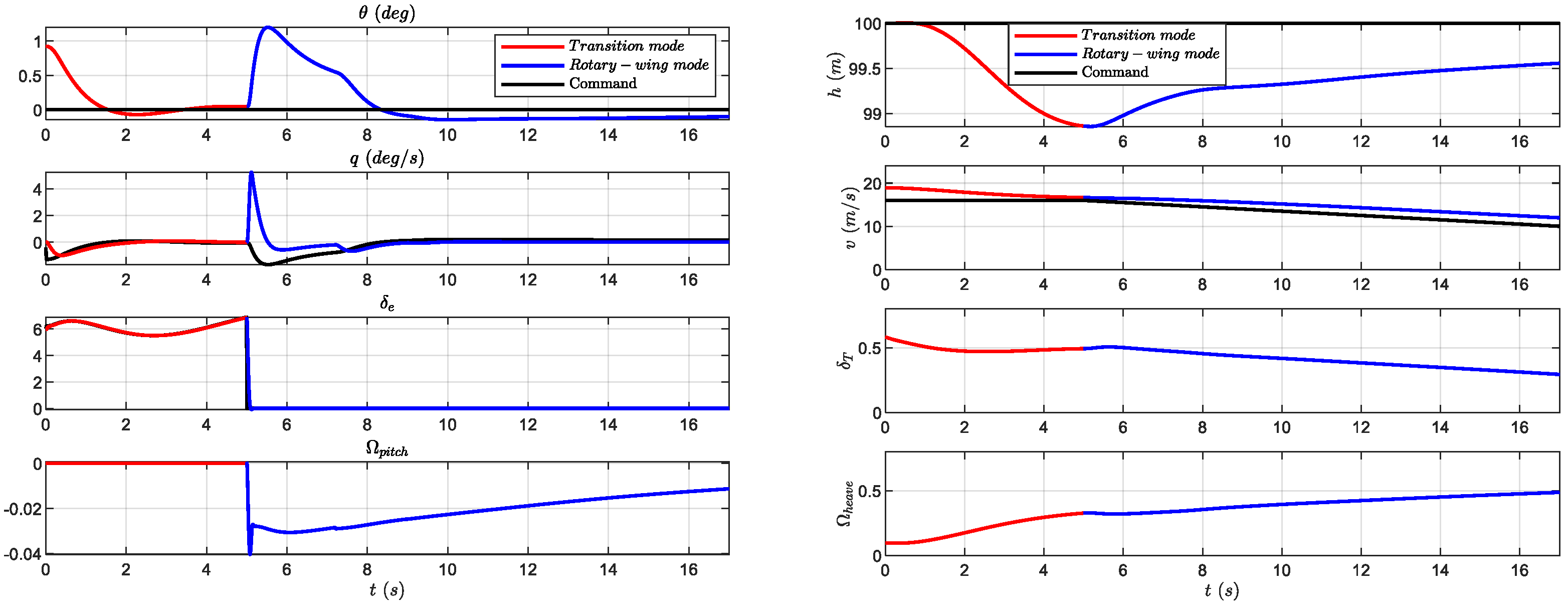
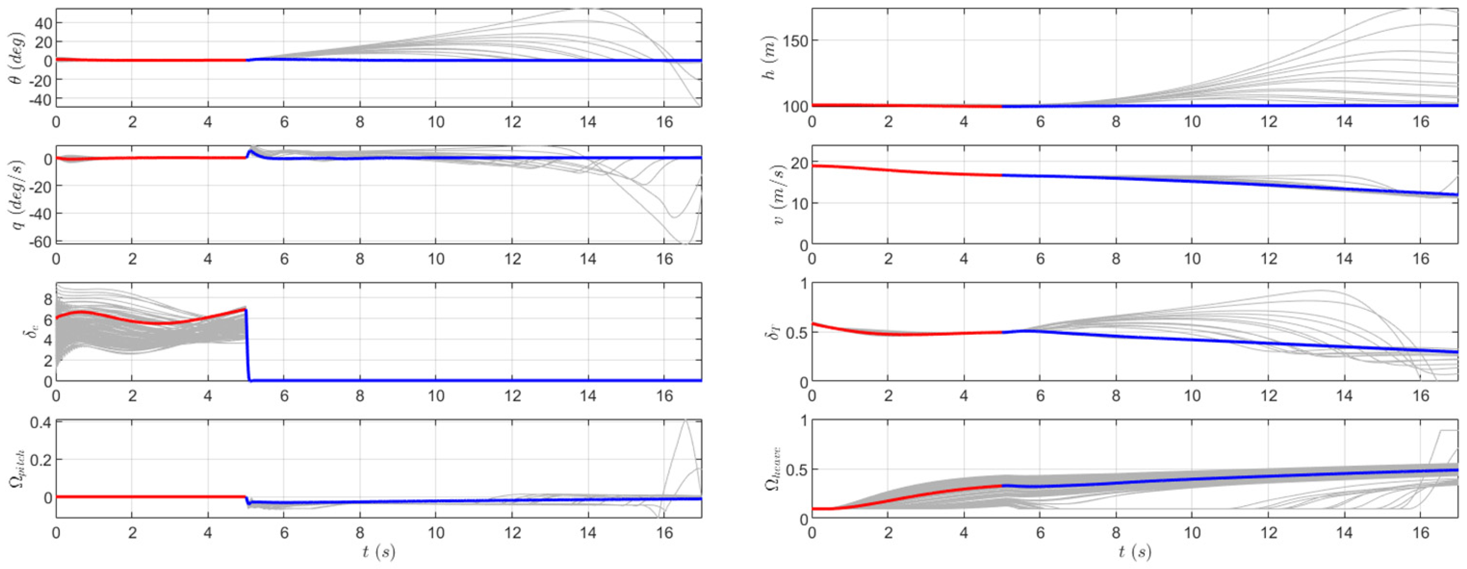
5.2. Simulation with 5 s Switching Mode

In the nominal simulation, it was observed that the UAV basically reached a steady state within 5 s after entering the switching mode, as shown in Figure 15. Therefore, the soft transition design of the 5 s switching mode was introduced for comparison.
Similarly, MC shooting simulation with 5 s switching mode uses the same random seeds with the same main parameter perturbations, and the simulation results are shown in Figure 16.
It can be observed that in the 100 MC shooting simulations, the mode switching task was completed well under most conditions, but there were also a few cases with perturbation of main parameters, resulting in poor altitude holding, throttle, and rotor speed saturation. As shown in Figure 17, details of the simulation results in Figure 16 are provided, and it was observed that, at the moment of switching to the rotary-wing mode (at the 5th second), the altitude channel had not yet entered a steady state. It was preliminarily judged that more time was needed to complete the altitude tracking, so it was considered to extend the duration of the mode switching for comparison.

5.3. Simulation with 10 s Switching Mode

Extending the duration of the switching mode to 10 s, the nominal simulation results are shown in Figure 18.
Similarly, MC shooting simulation with 10 s switching mode uses the same random seeds with the same main parameter perturbations, and the simulation results are shown in Figure 19.
It can be observed that under the condition of 20% model uncertainty with the same random seed, the results of all 100 MC shooting simulations show that the mode switching task was perfectly completed under the soft transition design with a duration of 10 s for the switching mode.

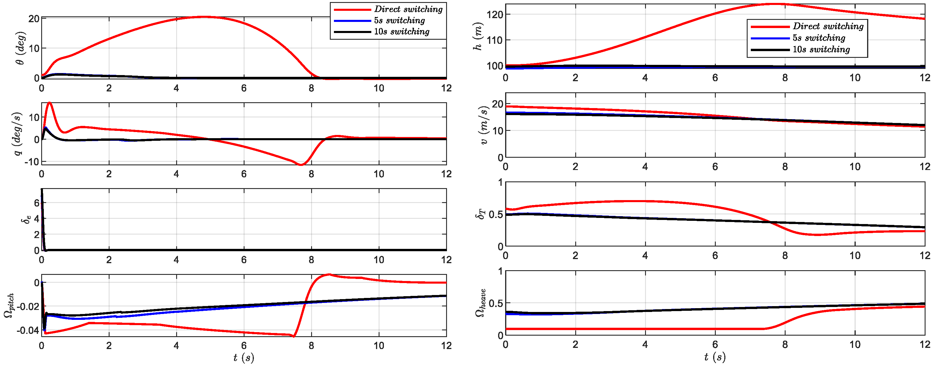
5.4. Compilation and Comparison of the Results of Three Transition Phase Designs

The deceleration process of fixed height, which is 12 s after switching to rotary-wing mode, is shown in Figure 20 and the three design methods of transition phase are compared.
The nominal simulation results under three transition phase designs are summarized and the distribution ranges of each parameter are shown in Table 4.
The comparison results in Table 4 show that:
  • A soft transition design with switching mode, after switching to rotary-wing mode, reduces the maximum pitch angle from 20.5° to 1.1°, by about 94%. In addition, the maximum pitch angle rate is reduced by about 72%. Therefore, it can inhibit the sudden change in pitch angle and pitch angle rate.
  • The soft transition design reduces the height fluctuation from 24 m to 1.1 m, which is a reduction of about 95%, so it has an enhanced effect on height maintenance.
  • The soft transition design reduces throttle usage by approximately 17% and therefore predictably withstands greater uncertainties, reducing the risks of δ T saturation.
  • When model uncertainty is excluded, the nominal simulation results of the soft transition design with a 5 s switching mode show little difference compared to the design with 10 s switching mode. Therefore, when UAV modeling is accurate, the soft transition design with 5 s switching mode is relatively ideal.
The comparison results in Table 5 show that:
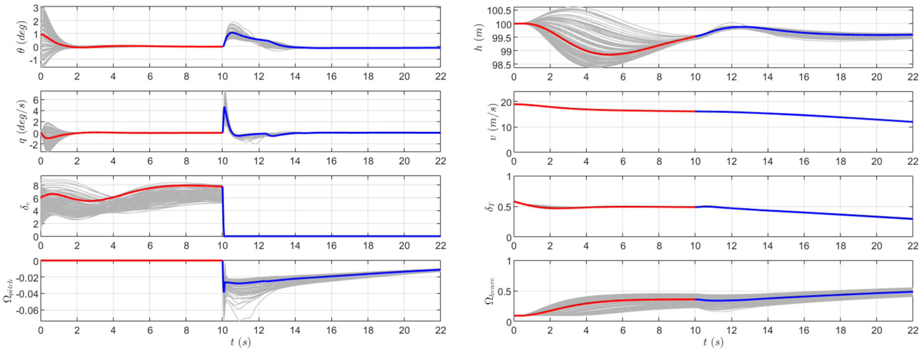
  • The design of the transition phase with 5 s has passed 100 MC shooting simulations with 20% model uncertainty. However, the design of the 10 s switching mode and the direct switching design have failed in some cases.
  • Under the random seed condition with poor pitch angle and height control in the 5 s switching mode design, good command tracking is obtained for the 10 s switching mode design. Therefore, the design of the transition phase with switching mode can effectively reduce the impact of model uncertainty and improve the robustness of the UAV transition phase, and the longer the duration of the switching mode within a certain limit, the better the flight stability.
  • Under the design of the 10 s switching mode, the occurrence of throttle and rotor speed saturation in a few extreme cases can be avoided. Therefore, extending the switching mode duration within a certain limit can reduce the possibility of extreme cases caused by mode switching, thereby improving the safety of the UAV transition phase.
Therefore, considering the uncertainty of the model, the MC shooting simulation results of the soft transition design with 10 s switching mode show greater advantages than those of the design with 5 s switching mode. For this type of UAV with inaccurate modeling, in order to achieve better robustness and safety, a 10 s switching mode is relatively more suitable.
Figure 20. Comparison between three designs for the transition phase.
Applsci 13 12225 g020

5.5. Quality Comparison of Mode Switching

The normal overload of an aircraft is the overload in the pitch direction perpendicular to the flight speed, which is the ratio of the centripetal acceleration to the gravitational acceleration. The aircraft will generate normal overload when performing pitch maneuvering flight. Normal overload will affect the equipment safety of the aircraft and the physiological condition of the pilot and passengers, such as excessive normal overload will also cause passenger comfort reduction and energy loss of the aircraft, and in serious cases even cause pilot loss of consciousness or black eye phenomenon and structural and airborne equipment damage of the aircraft.
Therefore, normal overload can be used as an important indicator to reflect the smoothness of mode switching. In UAV VtolA7, we believe that the limit normal overload within −1.5~3.8 can ensure the safety of the UAV and airborne equipment; considering the future manned scenario of air cars, a normal overload outside the range of −1~2.5 is considered unacceptable.
Figure 21 draws the normal acceleration diagram under three modes of switching in nominal simulation, which can intuitively and clearly outline the contrast between them, and also reflect the significance of normal overload as a soft switching indicator. The ranges of normal acceleration for the three modes are −0.29~0.23, −0.04~0.04, and −0.04~0.02, respectively, which imply ranges of normal overload of 0.71~1.23, 0.96~1.04, and 0.96~1.02, respectively. Therefore, in the nominal simulation, the soft switching design can decrease the maximum normal acceleration by about 86%, and the maximum normal load by about 17%.
As shown in Figure 22, the design of the transition segment can significantly reduce the overload limit caused by mode switching, which is manifested in:
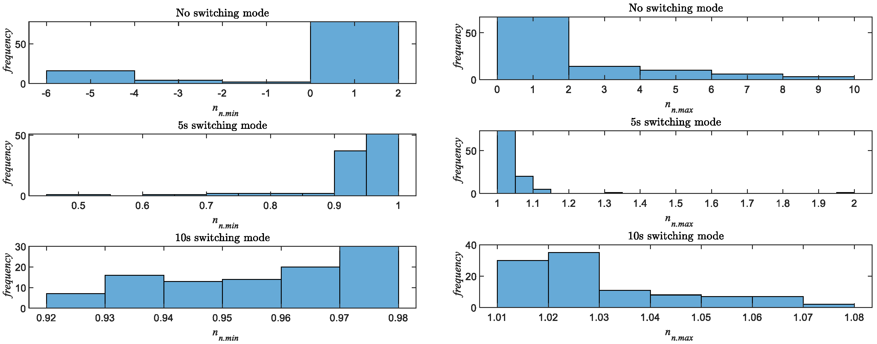
  • In the case of model uncertainty, there is a greater risk without a transition segment. Although the limit normal overload in 70% of cases is distributed between 0 and 2, it can reach −6 and 10 in extreme cases. Considering the future requirements of UAM vehicles for passenger comfort and equipment safety, direct switching is obviously a dangerous and fatal practice.
  • Under the soft switching design, the 5 s switching mode design can control the limits of the normal overload between 0.45 and 2, and about 90% of them are distributed between 0.9 and 1.1; in other words, the limit of the normal acceleration is within 0.1 to 1 times the gravitational acceleration. Therefore, the soft switching design of the 5 s switching mode can reduce the normal overload by about 80% and the limit of the normal acceleration by about 90% under the condition of 20% model uncertainty.
  • The 10 s switching mode design can control the limits of the normal overload between 0.92 and 1.08, and about 90% of them are distributed between 0.93 and 1.06, that is, the limit of the normal acceleration is within 0.06 to 0.08 times the gravitational acceleration. Therefore, under the condition of 20% model uncertainty, the soft switching design of the 10 s switching mode can reduce the normal overload by about 55% and the limit of the normal acceleration by about 90% compared with the 5 s switching mode design.
The soft switching design adopted in this paper can reduce the limit of the normal overload by about 17% under the condition of accurate model, and by about 89% under the condition of 20% model uncertainty. Therefore, especially for eVTOL aircraft with inaccurate modeling, there is a higher demand for soft switching, and a smooth switching design is needed to improve passenger comfort and solve the safety hazards caused by mode switching.

6. Conclusions and Prospects

This paper designs a soft transition control method for a compound-wing UAV VtolA7 based on the implicit NDI and INDI control law, which solves the safety problems in the transition phase from fixed-wing mode to rotary-wing mode. Moreover, this paper proposes the normal overload as a physical quantity that reflects the switching quality, which has guiding significance for the evaluation of soft switching, and reflects the value of soft switching for compound-wing aircraft.
The transition phase is a rather dangerous stage for compound-wing aircraft. This paper verifies and solves these problems in the transition phase:
  • The normal overload is too large, which affects the passenger comfort and equipment safety in future UAM applications;
  • Sensitivity to model uncertainty. Affected by its adverse effects, it poses a threat to flight safety;
  • Poor pitch attitude and altitude command tracking;
  • Throttle command and rotor command saturation.
This paper designs a soft switching control by using the method of rotor pre-start to compensate for lift, which realizes the smooth switching from fixed-wing mode to rotary-wing mode in the landing preparation phase. Through 100 Monte Carlo simulations with 20% model uncertainty, it is verified that soft switching can reduce the limit normal overload by 89%. Designing a soft switching strategy can reduce the adverse effects of model uncertainty, which not only ensures the safety of the aircraft, but also can be used to improve the passenger comfort, and provides a new idea for future UAM vehicles.
This paper finds the relatively suitable transition time by comparison, and finds that extending the duration of the transition switching mode to a certain extent is beneficial to reduce the adverse effects of model uncertainty. Therefore, finding out the appropriate duration of the transition phase is a necessary work, and is a process of optimizing the transition phase control strategy.
In the transition phase, the artificial setting of the duration of the switching mode is usually only applicable to the specific flight state of the specific aircraft. For various compound-wing UAVs, if a specific parameter is added to the autopilot module to determine whether the switching conditions are met, in other words, if it is up to the flight control system to determine the duration of the switching mode, then it is expected to better solve the robustness and safety problems of the transition phase of compound-wing UAVs. We intend to take this problem as a future research topic, to design a more widely applicable transition segment control method. The transition phase control of compound-wing UAVs is a challenging and innovative work, and also a promising research direction. We hope to see more progress and achievements in the future.

Author Contributions

Conceptualization, Y.C., H.L. and Z.G.; Methodology, Z.Y. and Y.C.; Software, Z.Y.; Validation, Z.Y.; Data Curation, Z.Y.; Writing—Original Draft, Z.Y.; Writing—Review and Editing, Y.C. and P.C.; Visualization, Z.Y. and P.C.; Supervision, J.W. All authors have read and agreed to the published version of the manuscript.

Funding

This research was funded by Aeronautical Science Foundation of China (Grant No. 2019ZA052001) and the Priority Academic Program Development of Jiangsu Higher Education Institutions (PAPD).

Institutional Review Board Statement

Not applicable.

Informed Consent Statement

Not applicable.

Data Availability Statement

The data presented in this study are available on request from the corresponding author. The data are not publicly available due to the data is based on a UAV model that involves some commercial content and these data need to be protected.

Conflicts of Interest

The authors declare no conflict of interest.

Nomenclature and Abbreviations

The following nomenclatures and Abbreviations are used in this manuscript:
Nomenclatures
LLift force
DDrag force
YSide force
lAerodynamic roll moments
mAerodynamic pitch moments
nAerodynamic yaw moments
ϕRoll Euler angle
θPitch Euler angle
VTrue airspeed
pRoll angular rate
qPitch angular rate
rYaw angular rate
αAngle-of-attack
δ e Deflection angle of the elevator
δ T Throttle command of front-mounted propeller
v g Ground speed
Abbreviations
eVTOLElectric vertical takeoff and landing
VTOLVertical takeoff and landing
UAVUnmanned aerial vehicle
NDINonlinear dynamic inversion
INDIIncremental nonlinear dynamic inversion
six-DOFSix-degree-of-freedom
ESOExtended state observer
MCMonte Carlo
LoDLift–drag ratio
nnNormal overload

References

  1. Courtin, C.; Burton, M.L.; Yu, A. Feasibility Study of Short Takeoff and Landing Urban Air Mobility Vehicles Using Geometric Programming. In Proceedings of the 2018 Aviation Technology, Integration, and Operations Conference, Atlanta, GA, USA, 25–29 June 2018; p. 70. [Google Scholar]
  2. Wang, M.; Zhang, S.; Diepolder, J.; Holzapfel, F. Battery package design optimizaiton for small electric aircraft. Chin. J. Aeronaut. 2020, 33, 2864–2876. [Google Scholar] [CrossRef]
  3. Laarmann, L.; Thoma, A.; Misch, P.; Röth, T.; Braun, C.; Watkins, S.; Fard, M. Automotive safety approach for future eVTOL vehicles. CEAS Aeronaut. J. 2023, 14, 369–379. [Google Scholar] [CrossRef]
  4. Sripad, S.; Viswanathan, V. The promise of energy-efficient battery-powered urban aircraft. Proc. Natl. Acad. Sci. USA 2021, 118, e2111164118. [Google Scholar] [CrossRef] [PubMed]
  5. Lee, Y.; Lee, J.; Lee, J.W. Holding area conceptual design and validation for various urban air mobility (UAM) operations: A case study in Seoul–GyungIn area. Appl. Sci. 2021, 11, 10707. [Google Scholar] [CrossRef]
  6. Edwards, T.; Price, G. eVTOL Passenger Acceptance (No. ARC-E-DAA-TN76992). 2020. Available online: https://ntrs.nasa.gov/citations/20200000532 (accessed on 17 October 2023).
  7. Mohsan, S.A.H.; Othman, N.Q.H.; Li, Y.; Alsharif, M.H.; Khan, M.A. Unmanned aerial vehicles (UAVs): Practical aspects, applications, open challenges, security issues, and future trends. Intell. Serv. Robot. 2023, 16, 109–137. [Google Scholar] [CrossRef] [PubMed]
  8. Ugwueze, O.; Statheros, T.; Horri, N.; Innocente, M.; Bromfield, M. Investigation of a Mission-based Sizing Method for Electric VTOL Aircraft Preliminary Design. In Proceedings of the AIAA Scitech 2022 Forum, San Diego, CA, USA, 3–7 January 2022; p. 1931. [Google Scholar]
  9. Qing, L.; Juanxia, L. Model and adaptive control of rotor/wing compound UAV based on derivative-free adaptive NDI. In Proceedings of the 2021 IEEE 4th International Conference on Electronics Technology (ICET), Chengdu, China, 7–10 May 2021; pp. 960–965. [Google Scholar]
  10. Doo, J.T.; Pavel, M.D.; Didey, A.; Hange, C.; Diller, N.P.; Tsairides, M.A.; Mooberry, J. NASA Electric Vertical Takeoff and Landing (eVTOL) Aircraft Technology for Public Services–A White Paper. 2021. Available online: https://ntrs.nasa.gov/citations/20205000636 (accessed on 15 October 2023).
  11. Bacchini, A.; Cestino, E. Electric VTOL configurations comparison. Aerospace 2019, 6, 26. [Google Scholar] [CrossRef]
  12. Ahmed, F.; Mohanta, J.C.; Keshari, A.; Yadav, P.S. Recent Advances in Unmanned Aerial Vehicles: A Review. Arab. J. Sci. Eng. 2022, 47, 7963–7984. [Google Scholar] [CrossRef]
  13. Yuksek, B.; Vuruskan, A.; Ozdemir, U.; Yukselen, M.A.; Inalhan, G. Transition Flight Modeling of a Fixed-Wing VTOL UAV. J. Intell. Robot. Syst. 2016, 84, 83–105. [Google Scholar] [CrossRef]
  14. Kamal, A.M.; Ramirez-Serrano, A. Design methodology for hybrid (VTOL+ Fixed Wing) unmanned aerial vehicles. Aeronaut. Aerosp. Open Access J. 2018, 2, 165–176. [Google Scholar]
  15. Xili, Y.; Yong, F.; Jihong, Z. Transition Flight Control of Two Vertical/Short Takeoff and Landing Aircraft. J. Guid. Control. Dyn. 2008, 31, 371–385. [Google Scholar] [CrossRef]
  16. Yuksek, B.; Inalhan, G. Transition Flight Control System Design for Fixed-Wing VTOL UAV: A Reinforcement Learning Approach. In Proceedings of the AIAA SCITECH 2022 Forum, San Diego, CA, USA, 3–7 January 2022; p. 0879. [Google Scholar]
  17. Juliana, S.; Chu, Q.P.; Mulder, J.A.; Van Baten, T.J. The analytical derivation of nonlinear dynamic inversion control for parametric uncertain system. In Proceedings of the AIAA Guidance, Navigation, and Control Conference and Exhibit, San Francisco, CA, USA, 15–18 August 2005; p. 5849. [Google Scholar]
  18. Kun, C.; Zhiwei, S.; Zheng, G. Deceleration Transition Control Law Design for Short Take-off Vertical Landing Unmanned Aerial Vehicle with Thrust Vector. J. Aerosp. Power 2015, 30, 3002–3009. [Google Scholar]
  19. Sieberling, S.; Chu, Q.P.; Mulder, J.A. Robust flight control using incremental nonlinear dynamic inversion and angular acceleration prediction. J. Guid. Control. Dyn. 2010, 33, 1732–1742. [Google Scholar] [CrossRef]
  20. Steffensen, R.; Steinert, A.; Smeur, E.J.J. Nonlinear Dynamic Inversion with Actuator Dynamics: An Incremental Control Perspective. J. Guid. Control. Dyn. 2023, 46, 709–717. [Google Scholar] [CrossRef]
  21. Luo, F.; Zhang, J.; Jiang, B. Robustness analysis of two advanced flight control laws: NDI and INDI. In Proceedings of the 5th China Aeronautical Science and Technology Conference; Springer: Singapore, 2021; pp. 660–668. [Google Scholar]
  22. Van’t Veld, R.; Van Kampen, E.J.; Chu, Q.P. Stability and robustness analysis and improvements for incremental nonlinear dynamic inversion control. In Proceedings of the 2018 AIAA Guidance, Navigation, and Control Conference, Kissimmee, FL, USA, 8–12 January 2018; p. 1127. [Google Scholar]
  23. Wang, X.; Van Kampen, E.J.; Chu, Q.; Lu, P. Stability analysis for incremental nonlinear dynamic inversion control. J. Guid. Control Dyn. 2019, 42, 1116–1129. [Google Scholar] [CrossRef]
  24. Lu, P.; Van Kampen, E.J.; De Visser, C.; Chu, Q. Aircraft fault-tolerant trajectory control using incremental nonlinear dynamic inversion. Control Eng. Pract. 2016, 57, 126–141. [Google Scholar] [CrossRef]
  25. Smeur, E.J.J.; Chu, Q.; De Croon, G.C.H.E. Adaptive incremental nonlinear dynamic inversion for attitude control of micro air vehicles. J. Guid. Control Dyn. 2016, 39, 450–461. [Google Scholar] [CrossRef]
  26. Acquatella, P.; Falkena, W.; van Kampen, E.J.; Chu, Q.P. Robust Nonlinear Spacecraft Attitude Control using Incremental Nonlinear Dynamic Inversion. In Proceedings of the AIAA Guidance, Navigation, and Control Conference, Minneapolis, MN, USA, 13–16 August 2012; p. 4623. [Google Scholar]
  27. Lombaerts, T.; Kaneshige, J.; Schuet, S.; Hardy, G.; Aponso, B.L.; Shish, K.H. Nonlinear dynamic inversion based attitude control for a hovering quad tiltrotor eVTOL vehicle. In Proceedings of the AIAA Scitech 2019 Forum, San Diego, CA, USA, 7–11 January 2019; p. 0134. [Google Scholar]
  28. Simplício, P.; Pavel, M.D.; Van Kampen, E.; Chu, Q.P. An acceleration measurements-based approach for helicopter nonlinear flight control using incremental nonlinear dynamic inversion. Control Eng. Pract. 2013, 21, 1065–1077. [Google Scholar] [CrossRef]
  29. Mokhtari, M.R.; Cherki, B.; Braham, A.C. Disturbance observer based hierarchical control of coaxial-rotor UAV. ISA Trans. 2017, 67, 466–475. [Google Scholar] [CrossRef] [PubMed]
  30. Lyu, H.; Ye, Z.; Chen, Y.; Zhao, T.; Gong, Z.; Liu, X.; Qin, B.; Chen, K. Extended-State-Observer-Based Angular Acceleration Estimation for Supersonic Aircraft Lateral–Directional Control. Appl. Sci. 2023, 13, 6598. [Google Scholar] [CrossRef]
  31. Mao, S.; Gong, Z.; Ye, Z.; Wang, Z.; Guo, T.; Zhang, C. A Linear-Active-Disturbance-Rejection-Based Vertical Takeoff and Acceleration Strategy with Simplified Vehicle Operations for Electric Vertical Takeoff and Landing Vehicles. Mathematics 2022, 10, 3333. [Google Scholar] [CrossRef]
Figure 1. Plan view of the research VtolA7 UAV.
Applsci 13 12225 g001
Figure 2. ET120, an existing UAM aircraft with a similar layout [31].
Applsci 13 12225 g002
Figure 3. Control mechanism of VtolA7 UAV.
Applsci 13 12225 g003
Figure 4. Block diagram of transition phase control.
Applsci 13 12225 g004
Figure 5. Diagram of altitude— θ control.
Applsci 13 12225 g005
Figure 6. Control structure of pitch angle.
Applsci 13 12225 g006
Figure 7. Control structure of pitch angle rate.
Applsci 13 12225 g007
Figure 8. Structure of ESO.
Applsci 13 12225 g008
Figure 9. Structure of throttle control.
Applsci 13 12225 g009
Figure 10. Structure of the three modes in transition phase design.
Applsci 13 12225 g010
Figure 11. The level flight trim curve of UAV VtolA7.
Applsci 13 12225 g011
Figure 12. UAV VtolA7 flight test records in fixed-wing mode.
Applsci 13 12225 g012
Figure 13. Nominal simulation of transition phase without switching mode.
Applsci 13 12225 g013
Figure 14. MC shooting simulation of transition phase without switching mode.
Applsci 13 12225 g014
Figure 15. Nominal simulation of transition phase with 5 s switching mode.
Applsci 13 12225 g015
Figure 16. MC shooting simulation of transition phase with 5 s switching mode.
Applsci 13 12225 g016
Figure 17. MC shooting simulation of 5 s switching mode.
Applsci 13 12225 g017
Figure 18. Nominal simulation of transition phase with 10 s switching mode.
Applsci 13 12225 g018
Figure 19. MC shooting simulation of 10 s switching mode.
Applsci 13 12225 g019
Figure 21. Schematic diagram of normal acceleration under nominal simulation trajectory.
Applsci 13 12225 g021
Figure 22. Histogram of extreme overload statistics from MC simulation.
Applsci 13 12225 g022
Table 1. General properties of the research aircraft.
ParameterExplanationValue
S Reference area 0.46 m2
b Wingspan 2.286 m
c Mean aerodynamic chord 0.2 m
m Mass 6.2 kg
I x Moment of inertia around the x-axis 0.5614 kg·m2
I y Moment of inertia around the y-axis 0.4479 kg·m2
I z Moment of inertia around the z-axis 0.87 kg·m2
Table 2. Comparison of flight test results and trim results.
Average ValueTrim Results
θ   ( deg ) 1.440.78
q   ( deg / s ) 0.160
δ e   ( deg ) 4.774.72
h   ( m ) 74.76100.00
v   ( m / s ) 19.2119.00
δ T 0.6110.582
Table 3. Perturbation range of main parameters.
ParametersExplanationRanges
m Mass±20%
I x x Inertial moment along x b ±20%
I y y Inertial moment along y b ±20%
I z z Inertial moment along z b ±20%
C m α Static derivatives±20%
C m δ e Control derivatives±20%
C m q Damper moment coefficient±20%
C L α Slope of lift curve±20%
T Thrust±20%
Table 4. Comparison of the ranges of state variables in nominal simulation.
Direct Switching5 s Switching Mode10 s Switching Mode
θ   ( deg ) −0.5~20.5−0.2~1.2−0.1~1.1
q   ( deg / s ) −11.6~16.5−1.7~5.3−1.0~4.7
δ e   ( deg ) −0.1~6.0−0.1~6.9−0.1~7.9
p i t c h −0.046~0.007−0.040~0−0.039~0
h   ( m ) 100.0~124.098.9~100.098.9~100.0
v   ( m / s ) 11.42~18.9211.97~18.9211.98~18.92
δ T 0.177~0.7000.294~0.5800.294~0.583
h e a v e 0.095~0.4430.095~0.4870.095~0.486
Table 5. Comparison of the ranges of state variables in MC simulation.
Direct Switching5 s Switching Mode10 s Switching Mode
θ   ( deg ) −83.7~82.7−49.6~54.8−1.6~3.1
q   ( deg / s ) −237.9~318.1−62.9~9.2−3.5~7.6
δ e   ( deg ) −0.1~9.5−0.1~9.5−0.1~9.5
p i t c h −0.407~0.443−0.114~0.412−0.0741~0
h   ( m ) 80.1~185.398.4~174.398.4~100.6
v   ( m / s ) 11.21~42.5511.15~18.9211.94~19.82
δ T 0~10~0.9120.280~0.599
h e a v e 0.095~0.8860.095~0.8860.095~0.552
Disclaimer/Publisher’s Note: The statements, opinions and data contained in all publications are solely those of the individual author(s) and contributor(s) and not of MDPI and/or the editor(s). MDPI and/or the editor(s) disclaim responsibility for any injury to people or property resulting from any ideas, methods, instructions or products referred to in the content.

