Article

An Evaluation of Cesium Removal from Simulated Radioactive Contaminated Soil with a Magnetized Zeolite Derived from Anthracite

Department of Radiochemistry, China Institute of Atomic Energy, Beijing 102413, China
*
Authors to whom correspondence should be addressed.
Appl. Sci. 2023, 13(22), 12192; https://doi.org/10.3390/app132212192
Submission received: 3 October 2023 / Revised: 25 October 2023 / Accepted: 1 November 2023 / Published: 10 November 2023
(This article belongs to the Section Environmental Sciences)

Abstract

:
The magnetized zeolite with an optimized conversion rate of 53% can be readily synthesized from industrial anthracite using a water-based method. The highly porous structure of ferromagnetism zeolite demonstrates robust magnetic properties with a magnetite content of 12–15%, satisfying adsorbent separation and recycling through magnetic cylinder rotating and vibrating separation. A cesium adsorption and removal efficiency as high as 99.92% with a corresponding adsorbent recovery ratio of up to 96.36% can be achieved for the simulated cesium-contaminated soil with a water content of 20% and a cesium content of 1% with an adsorbent-to-contaminated soil ratio of 1:2. Adsorption and magnetic separation technology with magnetized zeolite synthesized from anthracite exhibited a high cesium removal rate and zeolite recovery ratio, demonstrating promising application potential in treating radioactive waste soils and robust and economically viable engineering feasibility.

1. Introduction

More than 2000 nuclear tests, including military and commercial applications, have been carried out around the world since 1945, which has caused the worldwide spread of nuclear pollution [1]. The abundant long-lived radionuclides have penetrated into the ground soil and groundwater system through diffusion and transport and caused long-term harm to the local environment [2]. For example, the Chernobyl nuclear accident polluted the surrounding soil within a range of 4300 km2 with various radionuclides, such as Cs, Sr, Eu, Pu, and Am [3,4]. The Fukushima nuclear accident in Japan was estimated to contaminate buildings and roads within a land range of 1778 km2, in which the total amount of 137Cs-contaminated soil was 16–22 million m3 [5]. Radioactive contaminated soil usually features high concentrations of high-level waste with a range of radionuclides, which makes remediation challenging. Among these radioactive wastes, considerable 137Cs exists in spent fuel reprocessing liquid waste, the liquid nuclear waste generated during the operation of nuclear power facilities, and nuclear facility decontamination, and it is spontaneously released into the environment and causes soil pollution [5]. Therefore, 137Cs is the main nuclide in polluted soil, and it is a long-lived fission product that releases considerable heat (t1/2 = 30.08 years, a β/γ emitter) and has a half-life of approximately 30 years in high-level radioactive liquid waste [6]. High levels of 137Cs brought near the human body through inhalation or ingestion accumulate in tissue or muscles, which causes nausea, vomiting, diarrhea, bleeding, coma, or more severe scenarios leading to death [7].
Existing nuclear waste treatment technologies exhibit shortcomings, such as low decontamination efficiencies, low waste volume reduction ratios, and high cost-effectiveness ratios, and they might lead to byproduct production [8]. Research on the decontamination of radioactive contaminated soil initially began in the 1980s. A series of remediation strategies for the decontamination of soil containing radionuclides were developed, including chemical decontamination, physical decontamination, physical and chemical hybrid treatments, and biological remediation, based on the migration capacities of the radionuclides [9]. Specifically, chemical decontamination includes chemical extraction, electrokinetic decontamination, and heap leaching [10], while physical decontamination technologies include screening, flotation, separation gating, and in situ vitrification [11]. In the 1980s, the Pacific Northwestern National Lab (PNNL) in the United States developed an in situ vitrification technology (in situ vitrification ISV) to remediate soil with nuclear waste [12]. The Argonne National Laboratory (ANL) created a device for in situ vitrification of contaminated soils that simultaneously conducts radioactive waste treatment and research [13]. Moreover, physical and chemical hybrid treatment technologies were studied. Sidhu et al. (2004) showed that radioactive Pu was removed from contaminated soil via extraction with hydrochloric acid, nitric acid, and citric acid, and the nuclear waste removal rates were as high as 90% [14]. Sear et al. (1983) found that uranium removal was significantly improved with NaHCO3 as the eluting agent [15]. In addition, bioremediation, including phytoremediation and microbial remediation, has been studied recently due to the low costs and feasibility for use in large polluted fields [16]. Recent bioremediation of radioactive soil was carried out with sunflowers that were planted after the Fukushima accident in Japan [17]. The specific activities of radioactive Cs in the sunflower stems and roots were 52 Bq kg−1 and 148 Bq kg−1, respectively, while in the soil, it was 7715 Bq kg−1 after waste bioremediation [18].
Although numerous soil remediation technologies have been developed, the existing soil decontamination methods have disadvantages that limit their application [18]. For example, physical methods are relatively simple but usually involve considerable labor costs and can cause problems such as secondary pollution. Although the radioactive waste in soil is readily removed by chemical treatment, it is economically unfavorable and has low remediation efficiency, which is infeasible for the remediation of large areas of radioactive contaminated soil [13]. Biological methods, including bioremediation with plants, generally have long remediation periods and are limited by highly selective plants [18]. Therefore, new methods are urgently needed to increase the economic benefits of radioactively contaminated soil decontamination.
Recently, contaminated soil remediation through adsorption has been developed with various adsorbents [19]. Compared to the above-mentioned methods, adsorption through physical or chemical pathways has the advantages of high removal efficiencies, environmental safety, and favorable economics, and the adsorbents can be recycled and reused with magnetic separation processes. Zeolite with a general molecular formula of M2/nAl2O3∙xSiO2∙yH2O is a porous hydrous aluminosilicate mineral with anionic framework structure, where M is a metal ion, usually Na+ and K+, n is the valence of the metal ion, x is the amount of SiO2, and y is the amount of H2O. The composition of zeolites can be divided into A-type, X-type, Y-type zeolite, and mordenite based on the x value [20]. Furthermore, the silicon–oxygen tetrahedron or aluminum–oxygen tetrahedron of zeolite can be interconnected to form cavities and pores by more than 50% of the volume of the zeolite crystal with different shapes and sizes, resulting in a high surface area [21]. The adsorption capacity of zeolite can be activated and regenerated by heating. The highly porous structure of the zeolites can facilitate the adsorption of different kinds of molecules, depending on their molecule sizes. The different zeolites can absorb cations smaller than the micropores into the cavity while blocking cations larger than the pore size from adsorption, acting as a molecular sieve [20]. In addition, zeolite itself has good cation exchange performance, so zeolite exhibits unique selective adsorption characteristics for cations, which can be improved by pore modification [22]. Based on the above discussion, it is particularly important to detect and screen the appropriate raw materials to artificially design and synthesize proper zeolite adsorbent with a suitable pore size for the selective adsorption of Cs+ [23].
In the current study, a highly selective Cs+-magnetized zeolite adsorbent was prepared, and the adsorption capability was characterized with a laboratory-scale simulation, which will be detailed in the following section. The microstructure of the as-synthesized zeolite was characterized with scanning electron microscopy (SEM) and transmission electron microscopy (TEM). The crystallinity of the zeolite was determined with X-ray diffraction (XRD), while the magnetism was measured with magnetic hysteresis cycle analysis. The adsorbent was recovered and reused after decontaminating radioactive soil via magnetic separation with self-assembled magnetic recovery equipment. This technology significantly increased the soil decontamination efficiency while reducing secondary waste and recycling and reusing the adsorbent, which demonstrates promise for use in radioactive soil decontamination.

2. Materials and Methods
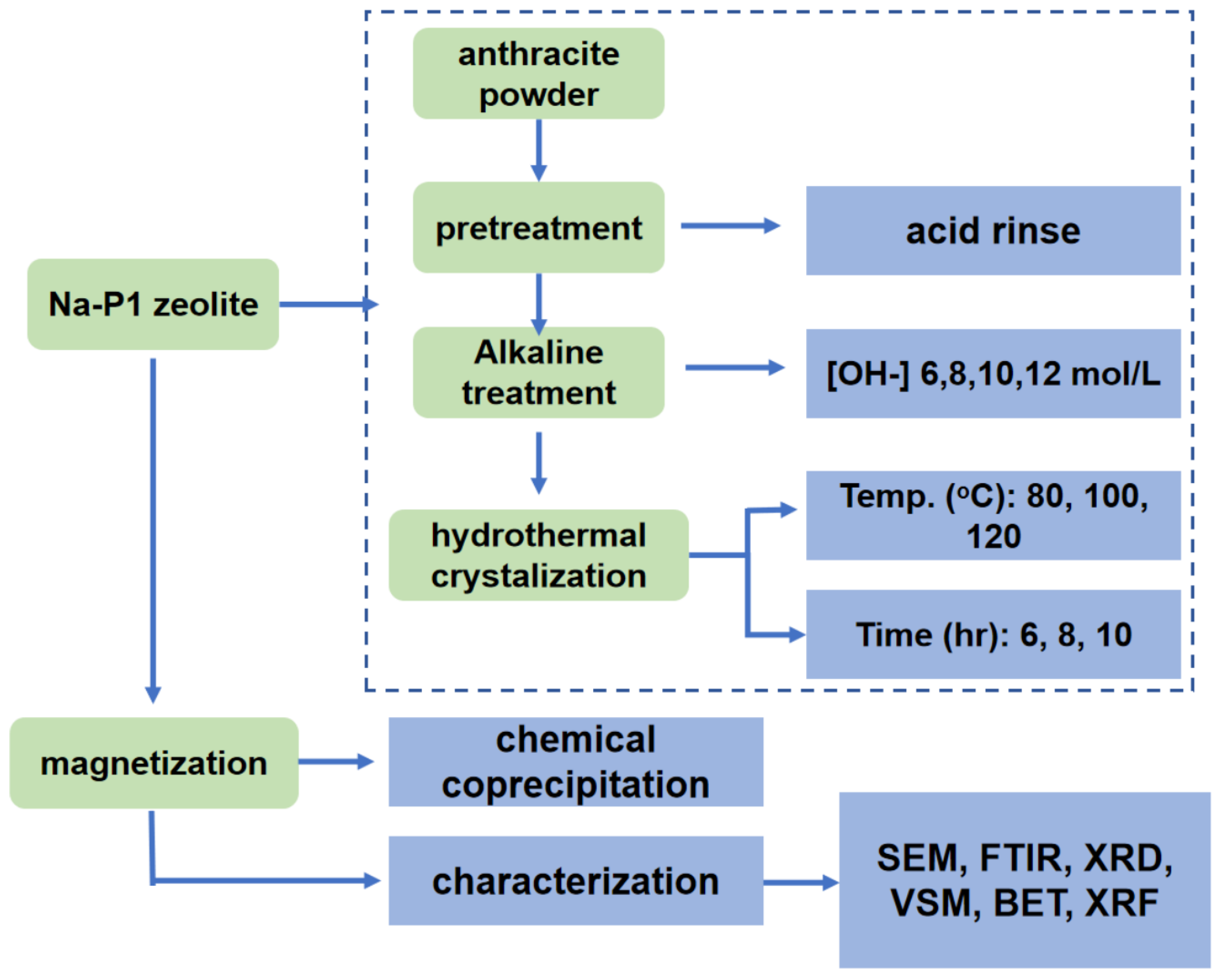
2.1. Materials

The anthracite used herein to synthesize the magnetized zeolite was obtained from the thermal power plants (Zhengzhou Yuzhong power plant, Zhengzhou, China), which can be sorted into three types based on their particle sizes, namely 1~3 mm, 60~80 mesh, and 80~120 mesh, as shown in Figure 1. The anthracite powder was first dried in a blast dry oven under 150 °C for 8 h, followed by pulverization to the designed particle sizes. The anthracite powder was further acidified by analytical pure hydrochloric acid (20 wt%) in a digitally controlled hot plate (NIB-946A, MTI, Hefei, China) under 80 °C with rigid agitation for 2 h, followed by rinsing with deionized water until pH equals 7.0. The harvested powder, named FA-1 to 3, was dried in an oven for further testing. The chemical composition of the anthracite powder was characterized by XRF and is shown in Table 1.

2.2. Synthesis of Magnetized Zeolite

The zeolite was synthesized from the anthracite powder using the hydrothermal method, which is specified below and described in the schematic in Figure 2. Anthracite powder (250 g) was first acid-washed to remove the adsorbed contaminates, followed by being alkalified with a mixing solution of NaOH (Analytical pure, Alfa Aesar, Haverhill, MA, USA) and KOH (Analytical pure, Alfa Aesar, Haverhill, MA, USA) with different levels of [OH-] concentration ranges of 6 mol/L, 8 mol/L, 10 mol/L, and 12 mol/L under 80 °C for 2 h. The mixture suspension was further filtered, and the slurry was rinsed with deionized water until neutralization. The dried powder post-alkaline solution modification was named base-treated (abbreviated as FB-1-1 to 3), as shown in the following Table 2.
Quartz powder with a grain size of 450 mesh (Sigma Aldrich, St. Louis, MO, USA), which belongs to the chemical composition of zeolite, was added to the treated anthracite with the assistance of NaOH and deionized water in order to adjust the ratio of SiO2 and Al2O3, as shown in the following Table 2. The mixture was further reacted and cured for 24 h in a PTFE reactor to trigger the crystallization of zeolite with controlled crystallization temperatures ranging from 80, 100, to 120 °C and a time regime of 6 h, 8 h, and 10 h.
The modified zeolite was further magnetized by mixing it with FeCl3·6H2O (Sigma Aldrich, St. Louis, MO, USA) solution (86 g/L) for 2 h, followed by sonicating treatment to stabilize the mixing suspension. FeCl2·4H2O (Sigma Aldrich, St. Louis, MO, USA) solution with a concentration of 37 g/L was then slowly added into the mixing suspension with high purity N2 protection, resulting in a solution with a Fe2+/Fe3+ ratio of 1:1.75. The pH of the solution with a total iron concentration of 0.5 mol/L was adjusted to 9.0 by 25% ammonia at 62 °C and stirred for 30 min. The solution was then filtered, and the slurry was further rinsed with deionized water to neutral and dried in an oven under 110 °C to achieve the magnetized zeolite for further testing.

2.3. Microstructure and Crystalline Phase Characterization

The elemental analysis of the as-synthesized zeolite sample was determined by X-ray fluorescience (XRF) (Thermo electron corporation, Waltham, MA, USA). The microstructures of the as-synthesized zeolite and magnetized zeolite were first dried in a digitally controlled oven under 95 °C for 24 h and further characterized by scanning electron microscopy (SEM) (S4800, HITACHI, Tokyo, Japan), transmission electron microscopy (H-9000NAR, HITACHI, Tokyo, Japan), and Brunauer–Emmett–Teller (BET) (Tristar 3020 II, Micrometrics Instrument Corporation, Norcross, GE, USA). The crystalline structure was further characterized by Fourier transform infrared spectroscopy (FTIR) (FTIR-650, GangDong Instrument Corporation, Shanwei, China) and X-ray diffraction (XRD) with a copper target and step size of 0.36° (D/max-rD, Jeol, Tokyo, Japan). The magnetic property of the zeolite was further characterized by magnetic hysteresis cycle analysis (BKT-4500, NACIS, Shanghai, China).

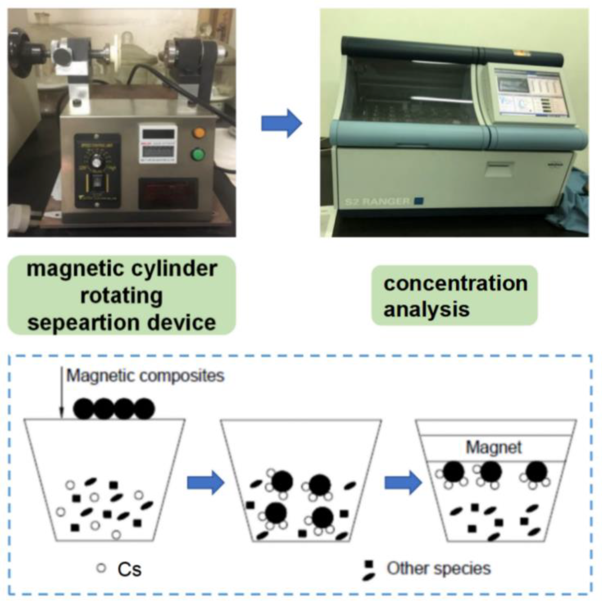
2.4. Simulated Leaching Experiment

The on-site performance and the adsorption property of the as-fabricated magnetized zeolite were characterized by mixing the magnetized zeolite powder with 10 g of target contaminated soil with CsCl (Sigma Aldrich, St. Louis, MO, USA) acting as the simulated Cs137 source. The simulated Cs-contaminated soil, with particle size detailed in Table 3, was prepared by mixing the CsCl with kaolinite (Sigma Aldrich, St. Louis, MO, USA) (20 wt% of moisture) using a mechanical stirrer (DX234, Guangdong, China) and keeping the Cs-to-soil ratio at 1%. The details of the simulated Cs-contaminated soil can be seen in the following table. The magnetized zeolite was thoroughly mixed with the simulated contaminated soil at room temperature, and we then waited 24 h before proceeding with the separation. The magnetization separation process of the contaminated soil and the magnetized zeolite can be further realized by a self-assembled magnetic cylinder separation device with a cylinder volume of around 50 mL, as shown in Figure 3. The rotating speed of the cylinder was kept at 50 rpm, and the vibration frequency was set at 200 Hz with a vibration impulse of 0.1 N∙s. The Cs concentration in the treated soil can be further determined by an X-ray fluorescence spectrometer (XRF) (PW4400, PANalytical, Almelo, The Netherland) with rhodium target X-ray tube with an energy of 60 kV and a current of 50 mA. The adsorption efficiency and recovery efficiency of the magnetized zeolite can be determined by the following Equations (1) and (2), where mr and m0 stand for the mass of magnetized zeolite recovered and the magnetized zeolite initial added, and Ct and C0 stand for the Cs concentration for the treated soil and intact soil separately:
Recovery   efficiency   ( θ ) = ( m r / m 0 ) × 100 %
Adsorption   efficiency   ( μ ) = ( C t / C 0 ) × 100 %

3. Results

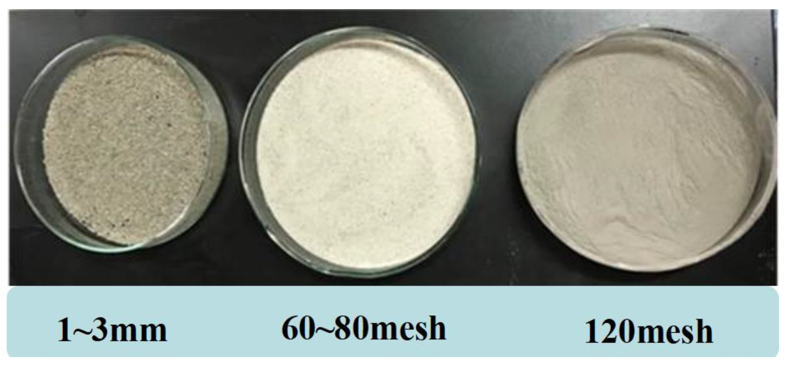
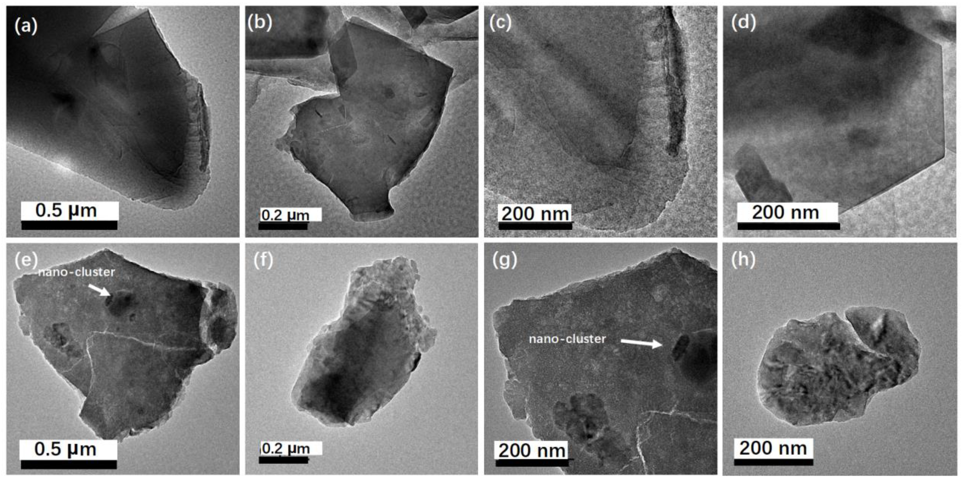
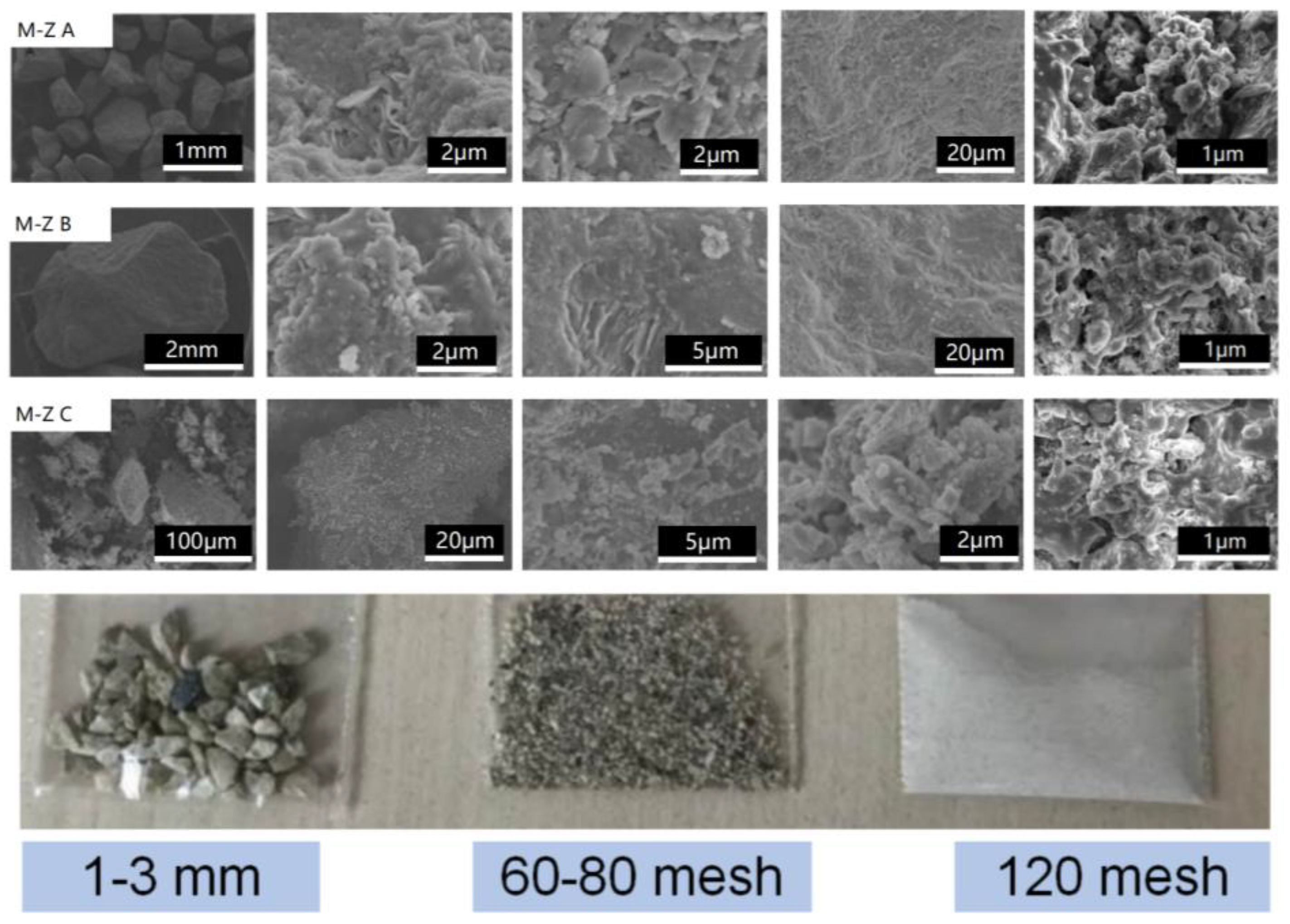
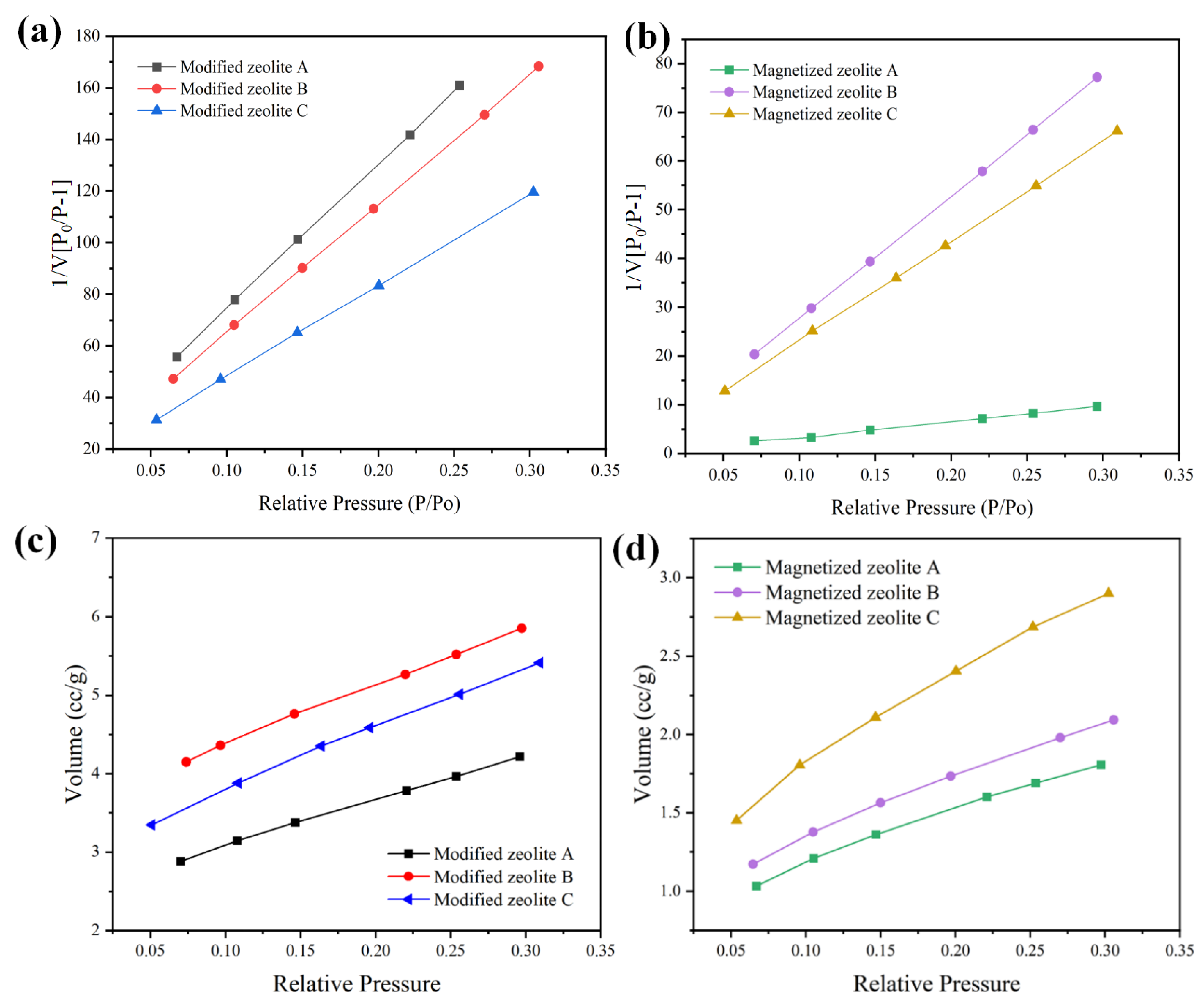
3.1. Microstructure and Phase Property of the Anthracite, Modified Zeolite, and Magnetized Zeolite

The microstructures of the anthracite raw material and the acid-washed anthracite powder were determined with SEM and TEM, and the images are shown in Figure 4 and Figure 5. The modified and magnetized zeolite is shown in Figure 6 and Figure 7. Fine particles were attached to the raw anthracite powder with particle sizes between 600 μm and 1 mm, according to SEM images processed with ImageJ software version 1.51 (NIH, Bethesda, MD, USA), which indicated agglomeration of the fine particles, as shown in Figure 4a–f. The surface fine particles contained residual organic compounds and metal oxides, as shown by the XRF data in Table 1; they were removed by acid washing, which exposed the spherical anthracite powder with particle sizes around 20 to 200 μm with an average particle size of 80 μm, as shown in Figure 4g–j and the corresponding particle partition chart [24]. A nanoscale microstructural analysis of the anthracite powder was carried out with TEM, as shown in Figure 5. The bright-field TEM images clearly indicated a hexagonal crystalline structure with black spots spread randomly on the anthracite particles before acid washing, which indicated residual contamination, probably from organic residues or metal oxides, consistent with the SEM images and the XRD analysis. The fine particles remaining on the anthracite were removed by acid rinsing, as shown in Figure 5e–h. In addition to the removal of the trace contaminants, the acid rinse further pulverized the anthracite grains, and the grain sizes were significantly reduced from the micron scale to 600 nm, as shown in the TEM image and the SEM analysis.
The microstructures of the alkaline-modified zeolite originating from the anthracite raw materials with different grain sizes are shown by the SEM image in Figure 6 and the corresponding photograph, while the magnetized zeolite is shown in Figure 7. Compared to the modified zeolite, the color in the optical images turned dark gray or black after magnetization, which was attributed to iron oxide nanoclusters precipitated on the modified zeolite from the alkaline solution (ammonia). The modified zeolite and the magnetized zeolite maintained microstructures similar to that of the tetrahedral zeolite without spherical structures, indicating a gradual phase transformation from anthracite to zeolite after the hydrothermal treatment. The high-resolution SEM images of the modified and magnetized zeolites in Figure 6 and Figure 7 show relatively high porosity and nano- and submicron pores. The particle sizes of the as-synthesized zeolite, including the alkaline-modified and magnetized zeolite, gradually increased with the particle sizes of the raw anthracite and featured a layered structure, as shown in Figure 6 and Figure 7. Numerous small pieces of the modified and magnetized zeolite agglomerated to form large particles for both the alkaline-modified and magnetized zeolites, with particle sizes of 1–3 mm, 60–80 mesh, and 120 mesh.
The surface areas, porosities, and nitrogen adsorption volumes of the as-synthesized zeolites were determined using the BET method, and the data are summarized in Figure 8 and Table 4 below. The BET tests were carried out with nitrogen adsorption–desorption isotherms at 200 °C and under nitrogen pressure up to 1 bar (Figure 8c,d). The specific surface area can be determined by the following equations [25]:
1 v [ p 0 / p 1 ] = c 1 v m c ( p p 0 ) + 1 v m c
v m = 1 s l o p e + i n t e r c e p t
c = 1 + s l o p e i n t e r c e p t
S B E T = v m N s a V  
where v is the amount of adsorbed gas, c is the BET constant, vm is the monolayer adsorbed gas volume, and a is the mass of the adsorbent. Although the adsorption isotherm, which reflects the adsorbed gas quantity, is low for the magnetized zeolite, the monolayer adsorbed gas volume might not decrease accordingly. As a result, the surface area is higher for magnetized zeolite compared to the modified zeolite, and the largest specific surface area of 109.443 m2/g was that of magnetized zeolite A with a particle size of about 3 mm. On the other hand, the specific surface area of the alkaline-modified zeolite with a specific surface area of approximately 6 m2/g was generally an order of magnitude lower than that of the magnetized zeolite, as shown in Figure 8 and Table 3. The specific surface areas of the modified zeolite and magnetized zeolite were lower than those of the synthesized Na-zeolite, consistent with previous research on Cu-impregnated zeolites, which can probably be attributed to the adsorption of Fe or K cations in the pores originating from the alkaline solution and iron chloride solution, which closed the pores [26]. Substitution of some of the surface cations by iron oxide nanoclusters as well as the ammonia treatment increased the number of open channels and the specific surface area, which facilitated adsorption [27]. Therefore, magnetization did not reduce the adsorption capacity because channels were opened by the alkaline solution treatment.

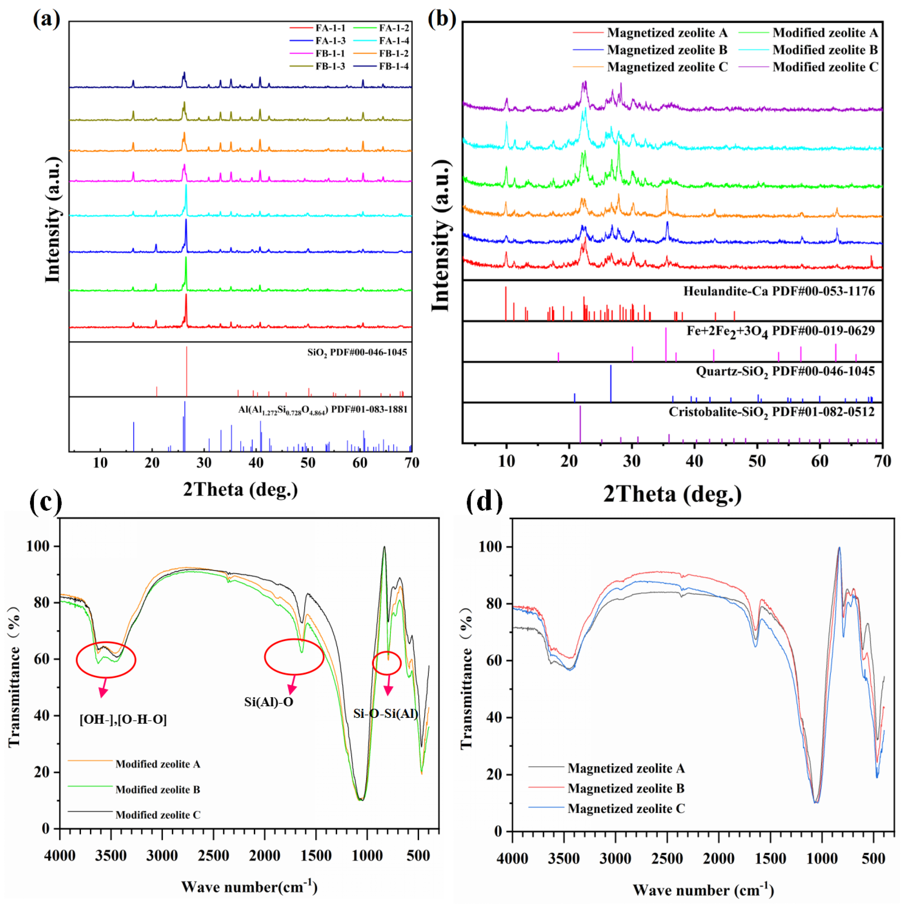
3.2. Crystalline Structure of Anthracite, Modified Zeolite and Magnetized Zeolite

The corresponding crystalline structure of the anthracite powder treated by variable concentrations of alkaline solution, as well as the as-fabricated modified and magnetized zeolites, can be seen in the following XRD profiles in Figure 9. The anthracite powder post different alkaline treatments demonstrates the same crystalline structure composed of silica and mullite without manifest crystalline phase degradation, as shown in Figure 9a, and the corresponding semi-quantitative phase analysis via Rietwald peak refinement, as shown in Table 5. Interestingly, the peak intensities are higher for FA-1-2, FA-1-4, FB-1-2, and FB-1-4, indicating a higher crystallinity, which does not have a close correlation with the alkaline solution concentration or anthracite powder size. The crystalline phase of mullite can be significantly enhanced with a decrease in the silica phase, which can be seen in Table 5. Partial metal oxides, including these rare earth oxides and the phosphate oxide, sulfur oxides, and chloride, have been eliminated by dissolving into the alkaline solution, as evidenced by the XRF analysis in Supplemental Table S1. The Si/Al ratio in the anthracite powder can be further adjusted by rinsing it with a base solution in order to facilitate zeolite formation. Specifically, the lowest ratio of Si and Al (corresponding to the ratio between silica and mullite) can be seen for the anthracite treated with a 10 mol/L alkaline solution, while the sodium ratio increases by elevating the alkaline concentration (Table 5). Therefore, it is suggested that the mixed alkali has a strong influence on the partition of SiO2 and Al2O3 in anthracite, causing a change in charge distribution between Si-O and Al-O bonds, thereby enhancing the polarization of chemical bonds and active centers (positive and negative charges) in the lattice, leading to bond relaxation in the tetrahedral structure of Si-O and Al-O bonds under the synergistic effect of time, temperature, and mixed alkali concentration, which would directly impact the zeolite transformation ratio [28]. The entire tetrahedral active core is exposed, the surface activation energy is increased, and the ion exchange capacity is enhanced so that Na+ enters the tetrahedral lattice to form a stable hole structure.
The anthracite transfer to zeolite through hydrothermal reaction under temperature ranges from 80 °C to 120 °C for 6 h, 8 h, and 10 h with the addition of different silica, NaOH, and deionized water following the protocols is outlined in Table 2. The anthracite with a dark gray color gradually transferred to a white color, as shown in Figure 6, suggesting the reaction-induced gradual crystallization of zeolite. The optimized zeolite yield rate of as high as 42% can be observed for the hydrothermal reaction with 10% of alkaline solution at a crystallization temperature of 120 °C for 8 h as denoted by the XRD analysis and corresponding Table 6. The corresponding XRD analysis for the modified zeolite indicates a major crystalline phase of zeolite, followed by Heulandite-Ca, cristobalite-SiO2, and silicon dioxide-SiO2, suggesting a complete re-crystallization and transformation reaction occurred [29].
On the other hand, the corresponding XRD profiles for the magnetized zeolite, as shown in Figure 9, further denote strong characteristic peaks indexed as iron oxides (magnetite Fe2O3) (PDF#00-019-0629) with an FCC crystalline structure, suggesting successful magnetization with the existence of iron oxide (Fe2O3). The iron incorporated as magnetite in the zeolite matrix can be further confirmed by previous research that suggested that Fe(III) dominated the crystalline phase agglomerated in the zeolite layer structure, according to XPS [30]. The corresponding semi-quantitative analysis by Rietwald peak refinement indicated the highest amount of magnetite can be seen for the magnetized zeolite B, followed by magnetized zeolite C and A, with corresponding compositions of 15 wt%, 13 wt% and 12 wt%, respectively, consistent with the XRD peak intensity as shown in Figure 9. In addition to the zeolite and magnetite, other crystalline phases of cristobalite, silica, and Heulandite can be further confirmed by the XRD profile and the semi-quantitative analysis. The XRF analysis demonstrates the composition of magnetite decreases from magnetized zeolite C to A, consistent with the XRD results, suggesting higher iron incorporation resulted from the particle size subdivision, as denoted in Table 7.
The FTIR spectra of the modified zeolite and magnetized zeolite demonstrate the existence of hydroxyl (OH-), water (O-H-O), and chemical bonding with a corresponding wave number higher than 3000 cm−1, while the peaks between 2000~1000 cm−1 and below 1000 cm−1 can be further attributed to Si(Al)-O vibration and Si-O-Si(Al) vibration separately [31], consistent with the FTIR spectra of typical Na-P1 zeolite with a chemical formula of Na6Al6Si10O32∙12H2O [32]. The Na-P1-type zeolite maintains a Gismodine structure with 2D cross-open channels following [100] and [010] directions, leading to superior ion exchange and adsorption ability. Furthermore, the pore diameter of Na-P1-type zeolite, around 3.6 Å, is close to the diameter of Cs+, suggesting excellent selective Cs+ capture ability [33], especially under a complex environment containing multiple ions. The magnetized zeolite demonstrates identical FTIR bands compared to the modified zeolite, indicating the iron oxide nano cluster incorporated into the zeolite crystalline structure as an inorganic crystalline phase without changing the original structure.

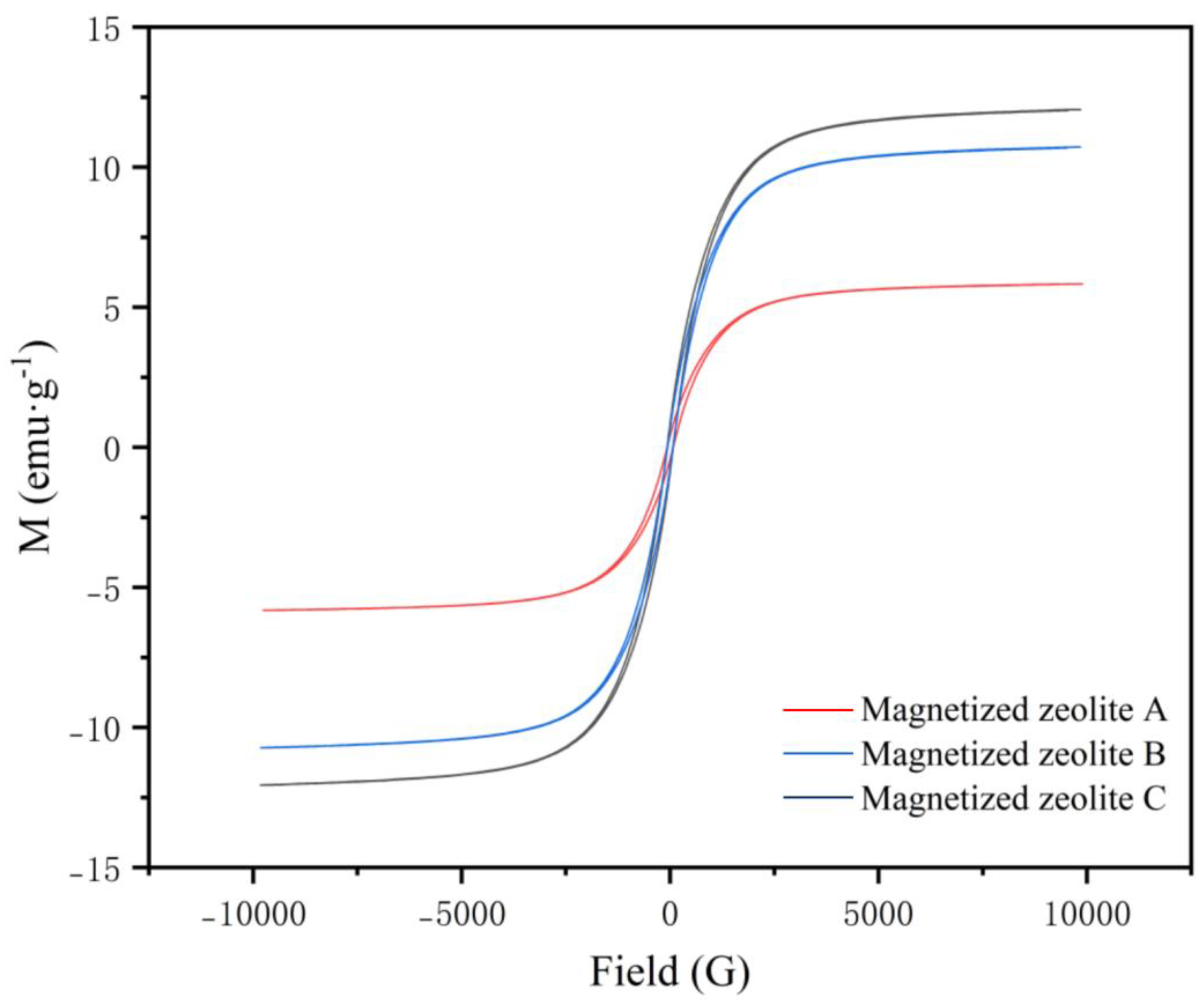
3.3. Magnetic Property of the As-Synthesized Magnetized Zeolite

The magnetization curve and hysteresis loop of the as-synthesized magnetized zeolite are shown in Figure 10, and the magnetization intensity data are summarized in Table 8. The results clearly indicated that the magnetized zeolites maintained high magnetization intensities, which would facilitate the separation and recovery of the zeolite powder from the contaminated soil sample (the higher the magnetization intensity is, the better the magnetization), which will be described in the following section. Similar ferromagnetism was seen in previous research, and the magnetism of the Fe-zeolite was attributed to the random distribution of Fe2+ and Fe3+ ions present to provide charge compensation for the oxygen vacancies and the magnetic interactions between them [30]. The pore volume of the magnetized zeolite was lower than that of the modified zeolite, although the average specific surface area was higher, which was attributed to the range of the pore sizes, consistent with previous research [26]. All three magnetized zeolites exhibited paramagnetism, and the magnetization decreased from zeolite C (12.055 A∙m2/kg) to B (10.722 A∙m2/kg) and A (5.8257 A∙m2/kg); these values were even higher than those reported in a previous study [30]. This was consistent with the iron concentrations indicated by the XRF analyses, so the higher magnetic intensity caused by particle subdivision resulted in a higher concentration of iron oxide nanoclusters.

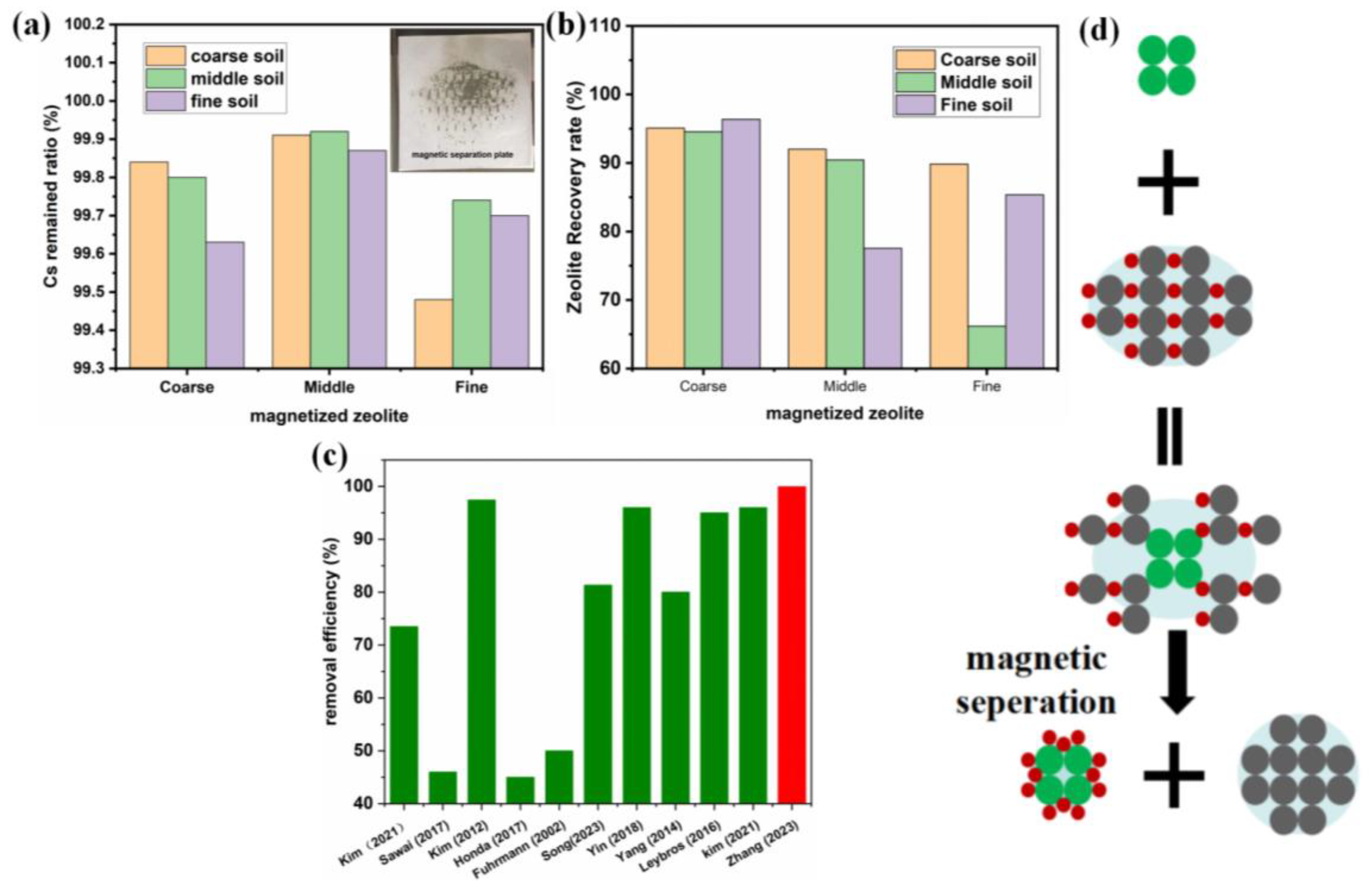
3.4. Cs+ Adsorption Efficiency and Magnetized Zeolite Recovery Efficiency

The Cs+ adsorption efficiencies and magnetized zeolite recovery efficiencies of the magnetized zeolites with different particle sizes were evaluated with 24 h cascade adsorption experiments using simulated Cs-contaminated soil, followed by magnetic separation and recovery for 1 min. The ratio of magnetized zeolite and soil (by weight) was kept at 0.5, and 3.33 g of magnetized zeolite was mixed with 6.67 g of wet contaminated soil (total weight of 10 g), while the Cs+ concentration in the contaminated soil was kept at 1 wt% with a 20 wt% moisture content in the soil, as shown in Table S2. The Cs+ concentration in the treated soil was characterized by XRF, and the adsorption efficiency was determined from the Cs+ remaining in the soil divided by the initial Cs+ concentration. The magnetized zeolite recovery ratio was determined by weighing the zeolite recycled in the magnetic separation cylinder, as shown in Figure 11 and Supplemental Table S2.
The results indicate that the magnetized zeolite exhibited efficient Cs+ adsorption and Cs+ removal rates up to 99.92% for the magnetized zeolite with 60–80 mesh particle sizes; this was inconsistent with the theoretical adsorption kinetics, which should be higher after particle subdivision. In theory, a fine-grained zeolite was sufficiently reactive in Cs+ adsorption, which was not the phenomenon operating herein [34]. The reason for this can be attributed to the intrinsic weakness of the operation process, which affects the separation of fine-particle zeolite. A small proportion of the fine-grained zeolite was blocked by the soil particles during the magnetic rotating vibration separation process in the magnetic cylinder, so that was not adsorbed by the inner wall of the magnetic cylinder and was carried into the product during the discharge process. The adsorption capacity of the magnetic zeolite with medium particle sizes was higher due to the better adsorption exchange reaction and breakthrough steric hindrance. The particle sizes of magnetized zeolite affected the removal rate of Cs+ in the soil and the waste reduction ratio in the above analysis. For actual polluted soil, the treatment would be improved by controlling the particle size range of the magnetized zeolite. The preparation process can be used to control the particle sizes appropriately.
Based on the different particle sizes of the contaminated soil and the zeolite, the magnetized zeolite could be recovered and recycled through magnetic treatment with a recovery ratio as high as 96%, as shown in Table S2. Generally, the magnetized zeolite was more efficiently recovered with coarse zeolite and finely contaminated soil, which should guide the design of the magnetized zeolite and the industrial treatment process [35]. The following table shows that the specific surface area of the coarse-grained zeolite was small, most of the pores with Cs+ adsorption and exchange capacity were located inside the particles, and the diffusion and exchange of Cs+ into the interior and the release of Na+ and K+ all required long reaction times. Therefore, the Cs adsorption and adsorbent recovery rates of the magnetized zeolite were summarized with the schematic in Figure 11d: the initial contact of the magnetized zeolite particles with the Cs-contaminated soil triggered adsorption, which was accelerated by agitation, followed by the adsorption of Cs in the pores of the zeolites. Separation and recovery of the magnetized zeolite were accomplished with an external magnetic field, for example, the magnetic cylinder designed herein.
Figure 11. The Cs adsorption (a) and recovery ratio (b) under room temperature with simulated Cs-contaminated soil for 24 h of the magnetized zeolites; the Cs removal efficiency compared to the literature [36,37,38,39,40,41,42,43,44] (c); the schematic figure illustrates the adsorption and recovery of magnetized zeolite (d).
Applsci 13 12192 g011
The performance of the magnetized zeolite studied herein was further compared to the previous literature research [36,37,38,39,40,41,42,43,44], as shown in Figure 11c and Table S3. Compared to the literature research, the Cs removal efficiency is significantly higher (99.92%) for the study herein, while the electrokinetic method can achieve a Cs removal rate of 97.6%, which ranks second in table. Although the electrokinetic washing method can reach as high Cs removal efficiency as the magnetized zeolite, the application of electrokinetic washing might pose other environmental concerns, which limits its application. Although the treatment conditions might vary depending on different scenarios, which makes it relatively difficult to make an accurate comparison, it is suggested that the magnetized zeolite studied herein demonstrates certain advantages for Cs-contaminated soil treatment. Overall, the magnetized zeolite studied herein enjoys advantages, including high efficiency, easy recovery, and low cost, which is of great significance for emergency radioactive soil remediation. However, the application of current adsorption and desorption methods based on magnetized zeolite is still limited by its Cs adsorption capacity, especially in an acid/base or high-salinity environment, which is closer to the real industrial scenario.

4. Conclusions

In the current study, a magnetized zeolite showing a high Cs removal efficiency was synthesized from anthracite, and the microstructure, textural properties, and crystalline structure were determined. The Cs adsorption and zeolite recovery properties were determined with a preliminary study of the magnetic separation technology for adsorption of simulated Cs+-polluted soil, and the conclusions are as follows:
(1)
The synthesis of the highly efficient magnetized zeolite adsorbent from anthracite is industrially feasible, and the yields ranged from 18 to 53%. The zeolite demonstrated high surface porosity and crystallinity, with tunable particle sizes.
(2)
The magnetized zeolite had saturation magnetic strengths of 12.055, 5.8257, and 10.722 emu g−1, which decreased with increasing particle sizes, and the magnetite content was 12% to 15%. The zeolite exhibited robust thermal stability at 75 °C.
(3)
The Cs+ removal rate from the simulated soil was as high as 92.82%, with a waste reduction ratio of 1.823 and a product recovery rate of 96.36%; there was no secondary waste generated, and the decontamination cost was low.
Overall, the cost-effective magnetized zeolite derived from anthracite demonstrates robust Cs adsorption and good adsorbent recovery efficiency, which shows promise for use in industrial applications in place of state-of-the-art Cs removal strategies.

Supplementary Materials

The following supporting information can be downloaded at https://www.mdpi.com/article/10.3390/app132212192/s1, Table S1: XRF measures fly ash composition after alkaline washing (wt%); Table S2: The Cs+ removal ratio and magnetized zeolite recovery ratio; Table S3: The Cs+ removal efficiency compare to literatures.

Author Contributions

Conceptualization, Y.Z. and S.Z.; methodology, X.Z. and Y.G.; investigation; writing—original draft preparation, Y.Z. All authors have read and agreed to the published version of the manuscript.

Funding

The current study was supported by the Governor’s Fund of China Institute of Atomic Energy (grant number YZ-163220).

Institutional Review Board Statement

Not applicable.

Informed Consent Statement

Not applicable.

Data Availability Statement

The data will be available upon request. Please contact the corresponding author for further information.

Conflicts of Interest

The authors declare no conflict of interest. The funders had no role in the design of the study; in the collection, analyses, or interpretation of data; in the writing of the manuscript; or in the decision to publish the results.

References

  1. Prăvălie, R. Nuclear Weapons Tests and Environmental Consequences: A Global Perspective. AMBIO 2014, 43, 729–744. [Google Scholar] [CrossRef]
  2. Gunten, H.R.; Benes, P. Speciation of Radionuclides in the Environment; 94-03; Paul Scherrer Institut: Villigen, Switzerland, 1994. [Google Scholar]
  3. Zelenina, D.; Kuzmenkova, N.; Sobolev, D.; Boldyrev, K.; Namsaraev, Z.; Artemiev, G.; Samylina, O.; Popova, N.; Safonov, A. Biogeochemical Factors of Cs, Sr, U, Pu Immobilization in Bottom Sediments of the Upa River, Located in the Zone of Chernobyl Accident. Biology 2022, 12, 10. [Google Scholar] [CrossRef] [PubMed]
  4. IAEA. Environment Consequences of the Chernobyl Accident and Their Remediation: Twenty Years of Experience; Radiological Assessment Reports Series; IAEA: Vienna, Austria, 2006.
  5. Yasunari, T.J.; Stohl, A.; Hayano, R.S.; Burkhart, J.F.; Eckhardt, S.; Yasunari, T. Cesium-137 deposition and contamination of Japanese soils due to the Fukushima nuclear accident. Proc. Natl. Acad. Sci. USA 2011, 108, 19530–19534. [Google Scholar] [CrossRef] [PubMed]
  6. Ojavan, M.I.; Lee, W.E. A Introduction to Nuclear Waste Immobilization; Elsevier: Amsterdam, The Netherlands, 2005; Chapter 11; pp. 645–655. [Google Scholar]
  7. Ha, M.; Ju, Y.-S.; Lee, W.J.; Hwang, S.-S.; Yoo, S.-C.; Choi, K.-H.; Burm, E.; Lee, J.; Lee, Y.-K.; Im, S. Cesium-137 Contaminated Roads and Health Problems in Residents: An Epidemiological Investigation in Seoul, 2011. J. Korean Med. Sci. 2018, 33, e58. [Google Scholar] [CrossRef]
  8. Lui, J.; Chen, W.-H.; Tsang, D.C.; You, S. A critical review on the principles, applications, and challenges of waste-to-hydrogen technologies. Renew. Sustain. Energy Rev. 2020, 134, 110365. [Google Scholar] [CrossRef]
  9. IAEA. Strategies And practices in the Remediation of Radioactive Contamination in Agriculture; IAEA: Vienna, Austria, 2016.
  10. Zhang, M.; Wang, X.; Yang, L.; Chu, Y. Research on Progress in Combined Remediation Technologies of Heavy Metal Polluted Sediment. Int. J. Environ. Res. Public Health 2019, 16, 5098. [Google Scholar] [CrossRef]
  11. USEPA. Technologuy Screening Guide for Radioactively Contaminated Sites; Technical Report; EPA 402-R-96-017; USEPA: Washington, DC, USA, 1996.
  12. Buelt, J.L.; Farthworth, R.K. In-Situ Vitrification of Soils Containing Various Metals; Technical Report; PNL-SA-17242; CONF-900210-35; Taylor & Francis: Abingdon, UK, 1990. [Google Scholar]
  13. Mazer, J.J.; Rosine, S.D.; No, J.J. Vitrification of Low-Level Radioactive Mixed Waste at Argonne National Laboratory; Waste Management; ANL--CMT/CP-85710; Argonne National Lab. (ANL): Argonne, IL, USA, 1995. [Google Scholar]
  14. Sidhu, R. Extraction Chromatographic Separation of Sr, Pu and Am in Environmental Samples. Ph.D. Dissertation, University of Oslo, Oslo, Norway, 2004. [Google Scholar]
  15. Sear, M.B.; Etnier, E.L.; Hill, G.S.; Patton, B.D.; Witherspoon, J.P.; Yen, S.N. Correlation of Radioactive Waste Treatment Costs and the Environmental Impact of Waste Effluents in the Nuclear Fuel Cycle-Conversion of Yellow Cake to Uranium Hexafluoride; Technical Report; ORNL/TM-8602; Oak Ridge National Lab.: Oak Ridge, TN, USA, 1983. [Google Scholar]
  16. Zhang, H.; Yuan, X.; Xiong, T.; Wang, H.; Jiang, L. Bioremediation of co-contaminated soil with heavy metals and pesticides: Influence factors, mechanisms and evaluation methods. Chem. Eng. J. 2020, 398, 125657. [Google Scholar]
  17. Li, Z.; He, Y.; Sonne, C.; Lam, S.S.; Kirkham, M.B.; Bolan, N.; Rinklebe, J.; Chen, X.; Peng, W. A strategy for bioremediation of nuclear contaminants in the environment. Environ. Pollut. 2023, 319, 120964. [Google Scholar] [CrossRef]
  18. Sasaki, H.; Shirato, S.; Tahara, T.; Sato, K.; Takenaka, H. Accumulation of Radioactive Cesium Released from Fukushima Daiichi Nuclear Power Plant in Terrestrial Cyanobacteria Nostoc commune. Microbes Environ. 2013, 28, 466–469. [Google Scholar] [CrossRef]
  19. Wang, L.; Gao, H.; Wang, M.; Xue, J. Remediation of petroleum-contaminated soil by ball milling and reuse as heavy metal adsorbent. J. Hazard. Mater. 2022, 424, 127305. [Google Scholar] [CrossRef]
  20. Win, H.H.; Aye, T.T.; Naing, K.M.; Wynn, N. Preparation and characterization of high silica molecular sieve from rice husk. J. Myan. Acad. Arts Sci. 2008, 6, 141–152. [Google Scholar]
  21. Vasconcelos, A.A.; Len, T.; Oliveira, A.d.N.d.; da Costa, A.A.F.; Souza, A.R.d.S.; da Costa, C.E.F.; Luque, R.; Filho, G.N.d.R.; Noronha, R.C.R.; Nascimento, L.A.S.D. Zeolites: A Theoretical and Practical Approach with Uses in (Bio)Chemical Processes. Appl. Sci. 2023, 13, 1897. [Google Scholar] [CrossRef]
  22. Zhang, J.; Tang, X.; Yi, H.; Yu, Q.; Zhang, Y.; Wei, J.; Yuan, Y. Synthesis, characterization and application of Fe-zeolite: A review. Appl. Catal. A Gen. 2022, 630, 118467. [Google Scholar] [CrossRef]
  23. Yıldız, B.; Erten, H.N.; Kış, M. The sorption behavior of Cs + ion on clay minerals and zeolite in radioactive waste management: Sorption kinetics and thermodynamics. J. Radioanal. Nucl. Chem. 2011, 288, 475–483. [Google Scholar] [CrossRef]
  24. Chen, X.; Srubar, W.V. Sulfuric acid improves the reactivity of zeolites via dealumination. Constr. Build. Mater. 2020, 264, 120648. [Google Scholar] [CrossRef]
  25. Walton, K.S.; Snurr, R.Q. Applicability of the BET Method for Determining Surface Areas of Microporous Metal−Organic Frameworks. J. Am. Chem. Soc. 2007, 129, 8552–8556. [Google Scholar] [CrossRef]
  26. Fajaroh, F.; Santoso, A.; Wardani, R.K. Performance of Activated Natural Zeolite/Cu as a catalyst on Degradation of Glycerol into Ethanol Assisted by Ultrasonic. In Proceedings of the 2017 International Conference on Mathematics, Science, and Education, Malang, Indonesia, 29–30 August 2017; Volume 1093. [Google Scholar]
  27. Szymaszek-Wawryca, A.; Díaz, U.; Samojeden, B.; Motak, M. Synthesis, Characterization, and NH3-SCR Catalytic Performance of Fe-Modified MCM-36 Intercalated with Various Pillars. Molecules 2023, 28, 4960. [Google Scholar] [CrossRef] [PubMed]
  28. Moafor, S.N.; Tsobnang, P.K.; Oyedotun, K.O.; Fomekong, R.L.; Kabongo, G.L.; Lebohang, M.; Lambi, J.N.; Jewella, L.L. Effect of SiO2/Al2O3 ratio on the electrochemical performance of amorphous zeolite loaded with cobalt oxide grown via steam-assisted crystallization method. RSC Adv. 2023, 31, 21393–21402. [Google Scholar] [CrossRef]
  29. Kuizumi, M.; Roy, R. Zeolite studies I Synthesis and stability of the calcium zeolites. J. Geol. 1960, 68, 41–53. [Google Scholar] [CrossRef]
  30. Murrieta-Rico, F.N.; Antúnez-García, J.; Yocupicio-Gaxiola, R.I.; Zamora, J.; Serrato, A.R.; Petranovskii, V. One-Pot Synthesis of Iron-Modified Zeolite X and Characterization of the Obtained Materials. Catalysts 2023, 13, 1159. [Google Scholar] [CrossRef]
  31. Lin, L.; Zhang, X.; He, N.; Liu, J.; Xin, Q.; Guo, H. Operando Dual Beam FTIR Study of Hydroxyl Groups and Zn Species over Defective HZSM-5 Zeolite Supported Zinc Catalysts. Catalysts 2019, 9, 100. [Google Scholar] [CrossRef]
  32. Ryu, G.U.; Khalid, H.R.; Lee, N.; Wang, Z.; Lee, H.K. The Effects of NaOH Concentration on the Hydrothermal Synthesis of a Hydroxyapatite–Zeolite Composite Using Blast Furnace Slag. Minerals 2020, 11, 21. [Google Scholar] [CrossRef]
  33. Yang, H.-M.; Jeon, H.; Lee, Y.; Choi, M. Sulfur-modified zeolite A as a low-cost strontium remover with improved selectivity for radioactive strontium. Chemosphere 2022, 299, 134309. [Google Scholar] [CrossRef]
  34. Navlani-García, M.; Miguel-García, I.; Berenguer-Murcia, Á.; Lozano-Castelló, D.; Cazorla-Amorós, D.; Yamashita, H. Pd/zeolite-based catalysts for the preferential CO oxidation reaction: Ion-exchange, Si/Al and structure effect. Catal. Sci. Technol. 2016, 6, 2623. [Google Scholar] [CrossRef]
  35. Yu, H.; Li, C.; Yan, J.; Ma, Y.; Zhou, X.; Yu, W.; Kan, H.; Meng, Q.; Xie, R.; Dong, P. A review on adsorption characteristics and influencing mechanism of heavy metals in farmland soil. RSC Adv. 2023, 13, 3505–3519. [Google Scholar] [CrossRef]
  36. Sawai, H.; Rahman, I.M.; Lu, C.; Begum, Z.A.; Saito, M.; Hasegawa, H. Extractive decontamination of cesium-containing soil using a biodegradable aminopolycarboxylate chelator. Microchem. J. 2017, 134, 230–236. [Google Scholar] [CrossRef]
  37. Song, H.; Nam, K. Development of a potassium-based soil washing solution using response surface methodology for efficient removal of cesium contamination in soil. Chemosphere 2023, 332, 138854. [Google Scholar] [CrossRef] [PubMed]
  38. Yang, H.; Li, H.; Zhai, J.; Sun, L.; Zhao, Y.; Yu, H. Magnetic prussian blue/graphene oxide nanocomposites caged in calcium alginate microbeads for elimination of cesium ions from water and soil. Chem. Eng. J. 2014, 246, 10–19. [Google Scholar] [CrossRef]
  39. Yin, X.; Horiuchi, N.; Utsunomiya, S.; Ochiai, A.; Takahashi, H.; Inaba, Y.; Wang, X.; Ohnuki, T.; Takeshita, K. Effective and efficient desorption of Cs from hydrothermal-treated clay minerals for the decontamination of Fukushima radioactive soil. Chem. Eng. J. 2018, 333, 392–401. [Google Scholar] [CrossRef]
  40. Kim, J.-H.; Kim, S.-M.; Yoon, I.-H.; Yang, H.-M.; Kim, I. Novel two-step process for remediation of Cs-contaminated soil assisted by magnetic composites. Chem. Eng. J. 2021, 424, 130554. [Google Scholar] [CrossRef]
  41. Leybros, A.; Grandjean, A.; Segond, N.; Messalier, M.; Boutin, O. Cesium removal from contaminated sand by supercritical CO2 extraction. J. Environ. Chem. Eng. 2016, 4, 1076–1080. [Google Scholar] [CrossRef]
  42. Kim, G.N.; Kim, S.S.; Kim, G.H.; Park, H.M.; Kim, W.S.; Park, U.R.; Kwon, H.J.; Ryu, O.H.; Moon, J.K. The removal of Cs-137 from soil using washing-electrokinetic decontamination equipment. In Proceedings of the Transactions of Korean Nuclear Society Autumn Meeting, Gyeongju, Republic of Korea, 25–26 October 2012; pp. 25–26. [Google Scholar]
  43. Fuhrmann, M.; Lasat, M.M.; Ebbs, S.D.; Kochian, L.V.; Cornish, J. Uptake of Cesium-137 and Strontium-90 from Contaminated Soil by Three Plant Species; Application to Phytoremediation. J. Environ. Qual. 2002, 31, 904–909. [Google Scholar] [PubMed]
  44. Honda, M.; Shimoyama, I.; Kogure, T.; Baba, Y.; Suzuki, S.; Yaita, T. Proposed Cesium-free Mineralization Method for Soil Decontamination: Demonstration of Cesium Removal from Weathered Biotite. ACS Omega 2017, 2, 8678–8681. [Google Scholar] [CrossRef] [PubMed]
Figure 1. Anthracite used to synthesize the zeolite with different particle sizes (1~3 mm, 60~80 mesh, and 120 mesh).
Applsci 13 12192 g001
Figure 2. Schematic figure demonstrates the preparation process of the magnetized zeolite from anthracite.
Applsci 13 12192 g002
Figure 3. Cs separation and adsorption testing procedure; the Cs-adsorbed zeolite can be successfully separated using a self-assembled magnetic cylinder, followed by a concentration analysis via an XRF.
Applsci 13 12192 g003
Figure 4. Microstructures of the anthracite (80 mesh) before and post-acid treatment demonstrating the significant morphology alteration; (af) raw anthracite; (gj); and acidtreated anthracites with corresponding particle size partition.
Applsci 13 12192 g004
Figure 5. TEM analyses of the anthracite (80 mesh) particle before (ad) and post-acid treatment (eh).
Applsci 13 12192 g005
Figure 6. Microstructures and the optical images of the alkaline-modified zeolite (M-Z A to M-Z C) derived from anthracite with different particle sizes.
Applsci 13 12192 g006
Figure 7. Microstructures and the optical images of the magnetized zeolite derived from the modified zeolite with different particle sizes.
Applsci 13 12192 g007
Figure 8. BET surface area test of modified and magnetized zeolites A, B, and C with elevated relative pressure: (a,b) the specific surface area; (c,d) nitrogen adsorption–desorption isotherms (200 °C).
Applsci 13 12192 g008
Figure 9. XRD and FTIR profiles of the modified zeolite and magnetized zeolite; (a) XRD profiles of the modified zeolites; (b) XRD profiles of the magnetized zeolites; (c) FTIR spectra of the modified zeolites; and (d) FTIR spectra of the magnetized zeolites.
Applsci 13 12192 g009
Figure 10. Hysteresis loop of the magnetized zeolites A to C.
Applsci 13 12192 g010
Table 1. XRF measures anthracite chemical composition assumed as oxides (mol/mol%).
SiO2Al2O3Fe2O3K2OTiO2Na2OMgOCaOP2O5Cl
57.55029.8303.9202.2600.8581.8801.4301.4600.1830.003
V2O5SrOZrO2La2O3CeO2MnOSO3Cr2O3WO3Co3O4
0.0220.0220.0120.0070.0010.0390.0390.0100.0020.003
Nd2O3CuOSc2O3Rb2ONiOZnOY2O3Ga2O3CeO2
0.0100.0050.0060.0040.0050.0050.0040.0020.007
Table 2. Shows the adjustment of Si and Al ratio through alkaline treatment.
Sample No. (10 g)SiO2/gNaOH/gH2O/g
FA-1-15.412.9116.4
FA-1-25.212.6113.6
FA-1-35.312.8115.4
FA-1-45.312.7114.7
FB-1-15.312.8115.0
FB-1-25.212.5112.2
FB-1-35.814.1126.9
FB-1-45.513.3120.1
Table 3. Particle size and partition of simulated soil.
Particle SizePartition (%)
<160 mesh2.97
60~160 mesh13.99
2 mm~60 mesh32.82
>2 mm50.22
Table 4. Specific surface area data of magnetized zeolite.
Sample NameSpecificationSpecific Surface Area m2/g
Magnetic zeolite A1–3 mm109.443
Magnetic zeolite B60–80 mesh13.704
Magnetic zeolite C120 mesh16.754
Modified zeolite A (M-Z A)1–3 mm6.013
Modified zeolite B (M-Z B)60–80 mesh6.769
Modified zeolite C (M-Z C)120 mesh9.511
Table 5. Semi-quantitative analysis of the anthracite post-alkaline treatment from the XRD profiles.
Alkaline Conc.SilicaMullite
FA-1-16 mol/L37%63%
FA-1-28 mol/L40%60%
FA-1-310 mol/L37%63%
FA-1-412 mol/L36%64%
FB-1-16 mol/L12%88%
FB-1-28 mol/L11%89%
FB-1-310 mol/L11%89%
FB-1-412 mol/L11%89%
Table 6. Semi-quantitative analysis of the zeolite derived from hydrothermal reaction from the XRD profiles (wt%).
ZeoliteMagnetiteSilicon DioxideCristobaliteHeulandite-CaMicrocline
Magnetized A60–80 mesh18%15%13%10%20%24%
Magnetized B1–3 mm53%12%16%19%--
Magnetized C120 mesh26%13%8%9%31%13%
Modified A1–3 mm26%-10%10%38%16%
Modified B60–80 mesh42%-12%14%21%12%
Modified C120 mesh23%-10%12%36%19%
Table 7. XRF data of magnetized zeolite (wt%).
Sample NumberSiAlFeKTiNaMgCaSrZrMn
Magnetic zeolite A39.687.7430.871.380.252.721.042.400.130.060.23
Magnetic zeolite B59.9411.3511.022.560.232.910.771.850.020.020.12
Magnetic zeolite C58.2011.7910.842.520.163.400.851.950.020.010.10
Modified zeolite A70.2512.500.833.780.152.760.440.960.020.020.07
Modified zeolite B70.6212.371.073.040.083.310.421.370.060.030.06
Modified zeolite C69.0613.561.133.280.110.780.782.570.020.010.05
Table 8. VSM result of the magnetized zeolites.
Sample No.SizeSaturated MagnetizationResidual MagnetizationRectangle RatioCoercive Force (Hc/G)
Ms (A∙m2/kg)Mr (A∙m2/kg)
Magnetized zeolite A1–3 mm5.82570.406360.0772.115
Magnetized zeolite B60–80 mesh10.7220.681840.06463.611
Magnetized zeolite C120 mesh12.0550.823130.06871.612
Disclaimer/Publisher’s Note: The statements, opinions and data contained in all publications are solely those of the individual author(s) and contributor(s) and not of MDPI and/or the editor(s). MDPI and/or the editor(s) disclaim responsibility for any injury to people or property resulting from any ideas, methods, instructions or products referred to in the content.

