
A Large-Diameter Earth–Air Heat Exchanger (EAHX) Built for Standalone Office Room Cooling: Monitoring Results for Hot and Dry Summer Conditions


Abstract
:1. Introduction
2. Materials and Methods
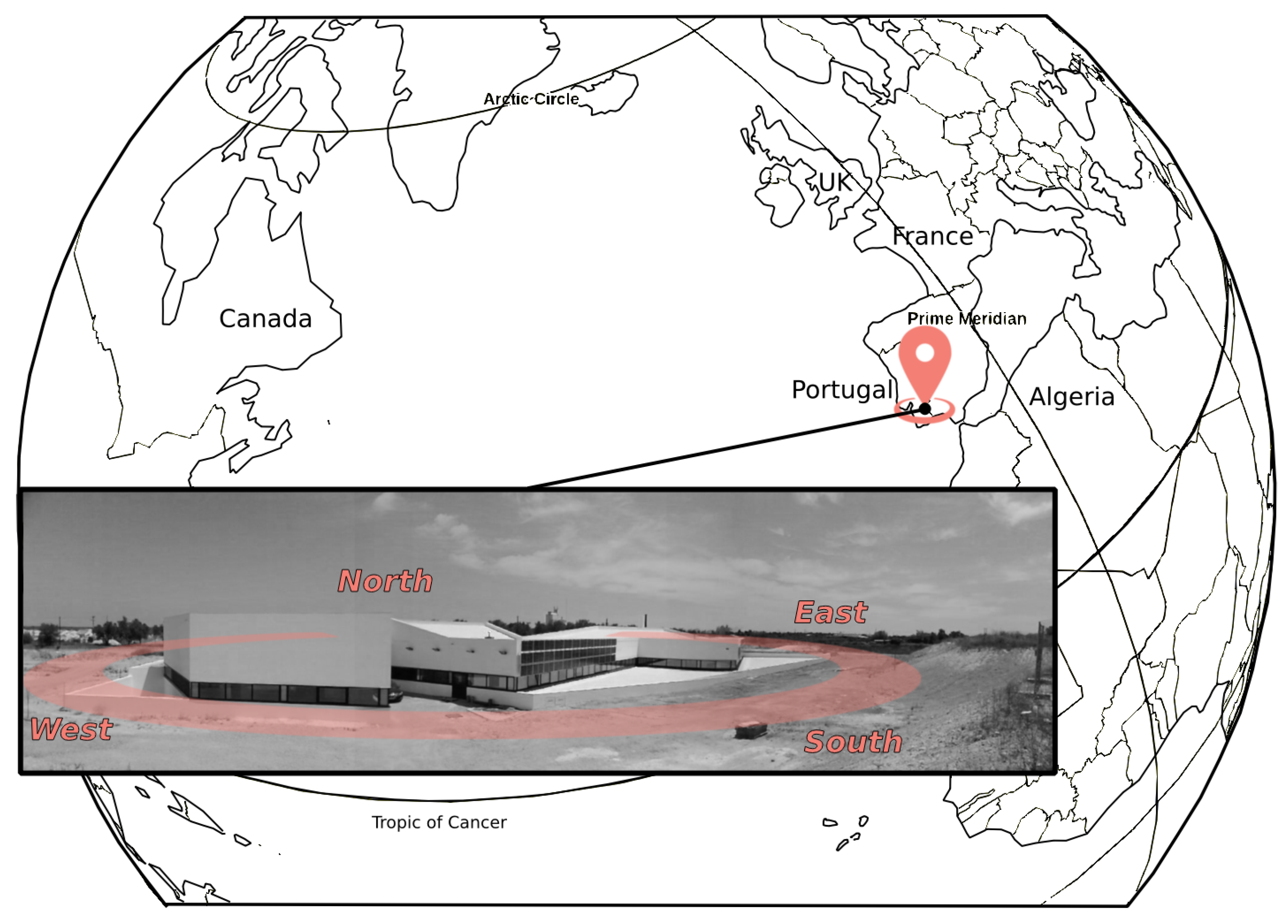
2.1. The Building Served by the EAHX: Location, Climate and Relevant Features
2.2. The Cooling and Ventilation System
2.3. EAHX Performance Assessement
- EAHX outdoor air load removal,
- EAHX room load removal,
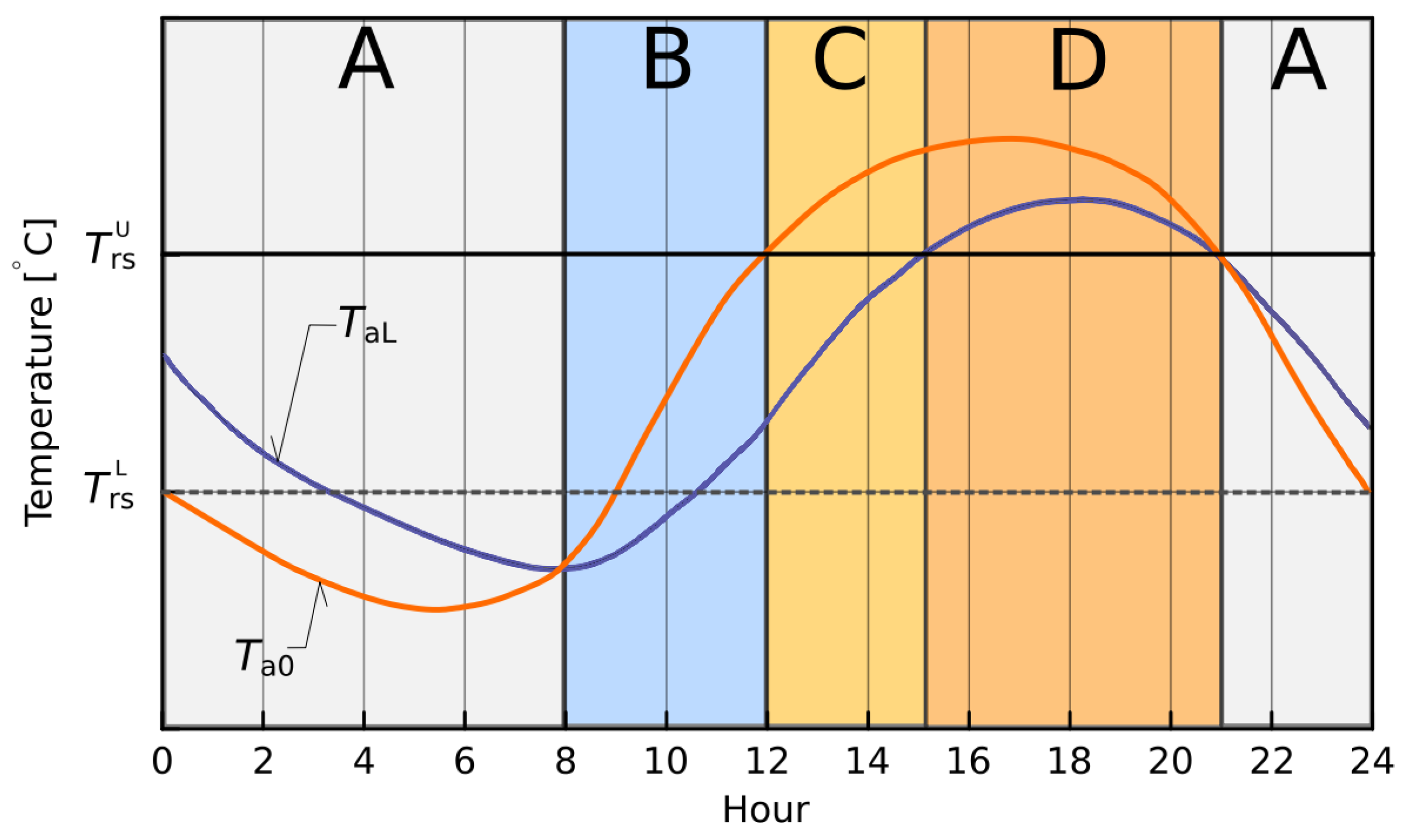
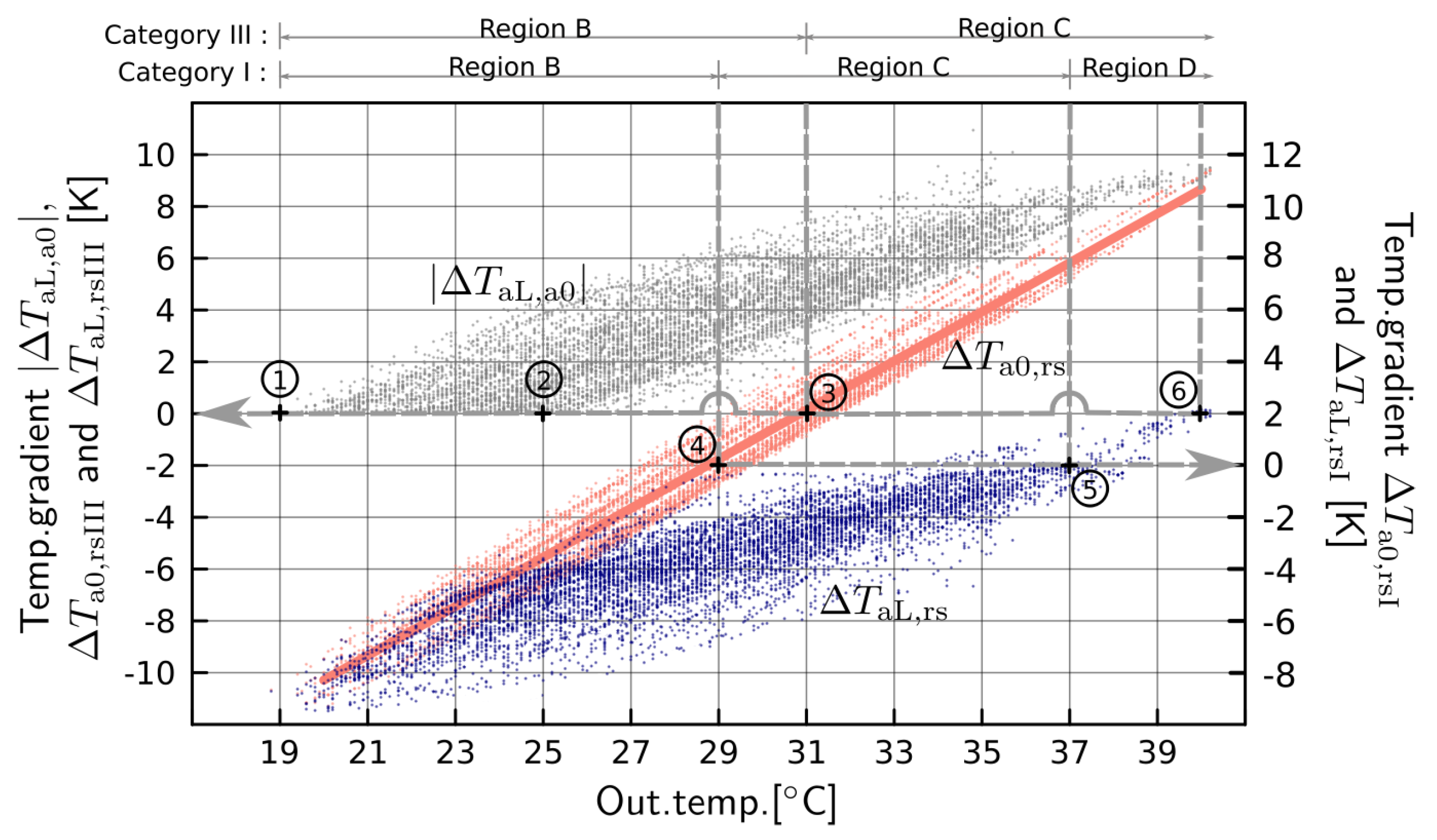
- Region A: Nighttime (from evening to the start of the working day) with outdoor air temperature lower than EAHX exit air temperature, .In this region, the EAHX heats the outdoor air, operating, therefore, in heating mode. Since this paper discusses cooling performance, Region A is excluded from the analysis.
- Region B: From the start of the working day to noon with EAHX exit air temperature lower than outdoor air temperature and both of these lower than the upper room setpoint temperature, .In this region, the EAHX cools the outdoor air, operating, therefore, in cooling mode. Since the outdoor air temperature is lower than the room upper setpoint temperature, EAHX room load removal has two components,namely, the EAHX outdoor air load removal component, ; and the outdoor air room free-cooling component, (actually, this latter component is independent of the EAHX; however, because the flow of outdoor air in large-diameter EAHXs has negligible added fan cost—negligible pressure losses—, is absorbed into ). In Equation (6), the outdoor air to room upper setpoint temperature gradient, , is defined as,In region B, due to outdoor air free cooling, the following inequation applies: .
- Region C: Start of the afternoon with EAHX exit air temperature lower than the room upper setpoint temperature and both of these lower than outdoor air temperature, .In this region, outdoor air makes no contribution to room cooling; still, it is customary to distinguish two components in the EAHX outdoor air load removal,namely, the EAHX room load removal component, , and a component for the EAHX outdoor air load removal to the “neutral” state, , withbeing the temperature gradient that brings outdoor air to the room upper setpoint temperature, i.e., the condition for which outdoor air neither heats nor cools the room (“neutral” state).In region C, the following inequation applies:
- Region D: During the afternoon, with room upper setpoint temperature lower than EAHX exit air temperature and both of these lower than outdoor air temperature, .In this region, since EAHX exit air temperature exceeds the room upper setpoint, the EAHX is incapable of removing room loads, . The EAHX operates for outdoor air load removal only.
- In region B, the EAHX complements free cooling with outdoor air, increasing room load removal.
- In region C, the EAHX replaces free cooling with outdoor air, increasing the duration of room load removal.
- A prime sizing requirement for standalone EAHX cooling is to avoid region D, i.e., for cooling design conditions, inequations and should stand.
2.4. Monitoring
3. Results and Discussion
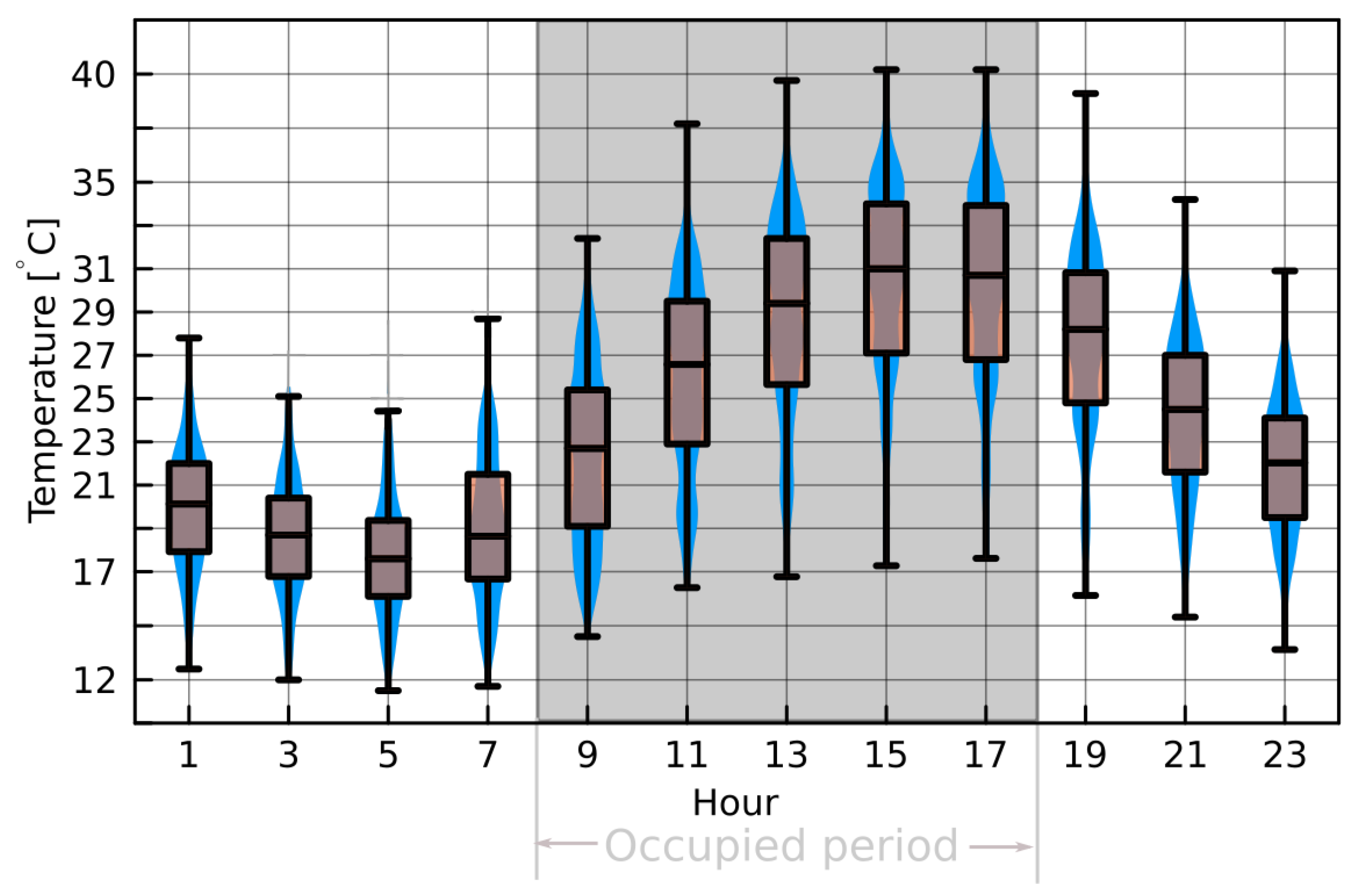
3.1. Outdoor Conditions and Challenges Facing Standalone EAHX Cooling
3.2. EAHX Exit Air Temperature: Assessing EAHX Room Load Removal
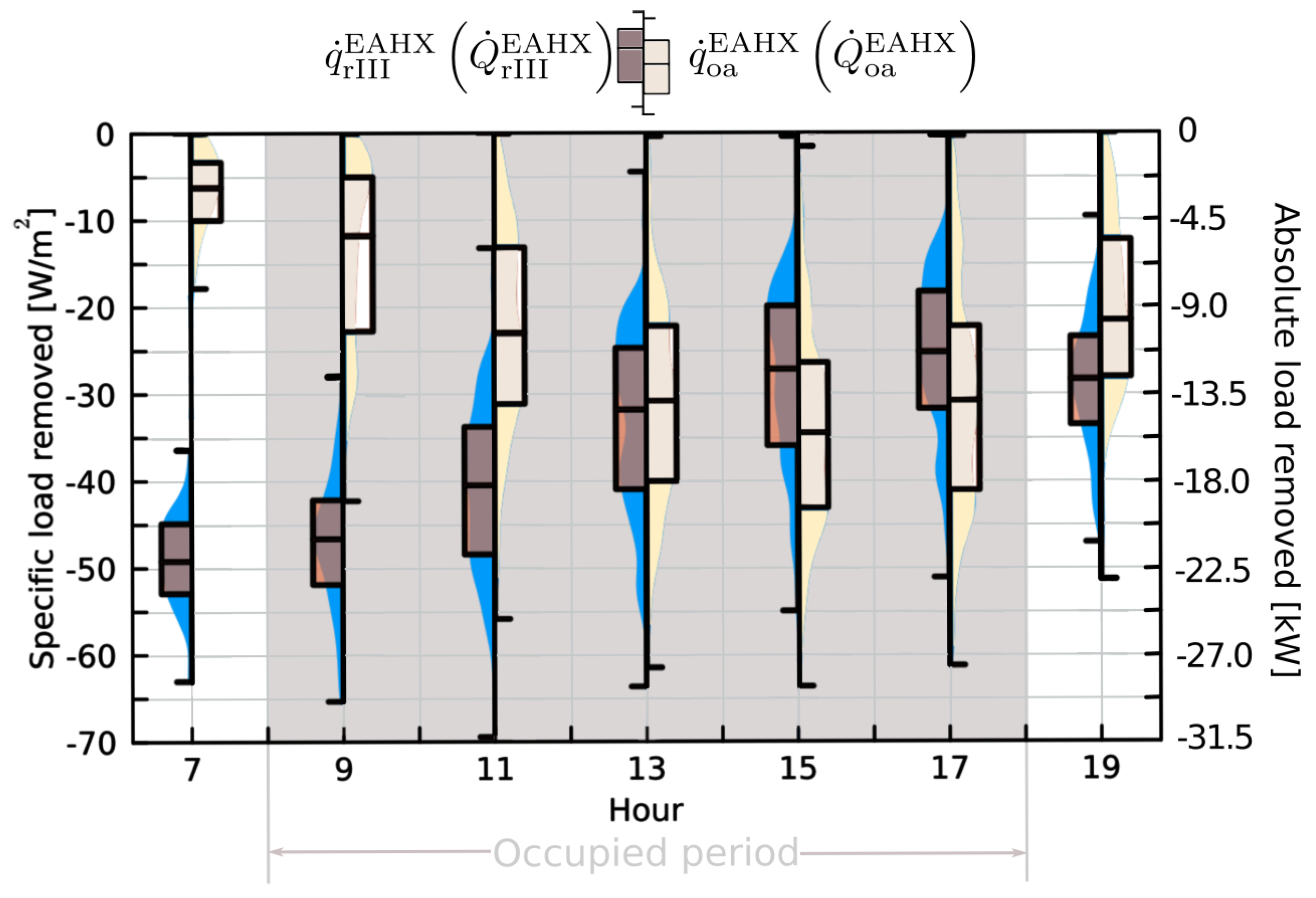
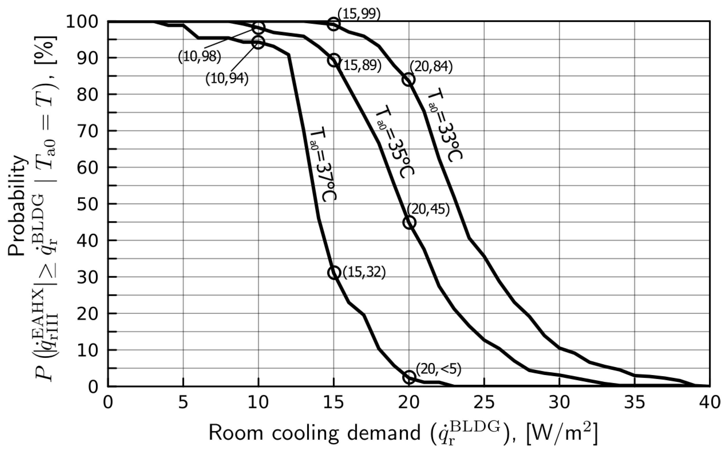
3.3. EAHX Room Load Removal: Assessing Standalone EAHX Cooling and EAHX Design
- (i)
- (ii)
- For outdoor air temperatures exceeding 33 °C, the built EAHX allows for room cooling during the whole summer; however, room load removal is insufficient to meet the room design cooling demand. If room comfort Category III is judged to be appropriate, the built EAHX provides, on its own, more than 50% of the room design cooling demand.
- (iii)
- 1.
- Alter the EAHX design; for example, increase pipe length, change pipe layout.
- 2.
- Complement EAHX room load removal with passive cooling techniques, e.g., forced nighttime ventilation and appropriate use of building thermal mass.
4. Conclusions
- The large temperature difference between the undisturbed soil temperature (∼17 °C) and the room upper setpoint (∼30 °C, considering adaptive comfort principles [29]) confirmed the feasibility of EAHX standalone cooling.
- Daily maximum EAHX outflow temperatures can be 9 K lower than the simultaneous outdoor air temperatures and results confirm that air exits the EAHX at temperatures that never exceed room upper setpoint for Category III, and that seldom exceed room upper setpoint for Category I comfort expectancy level [29].
- Median values of EAHX specific room load removal are larger than 20 W/m, the room design cooling demand; however, smaller EAHX room load removal occurs during the afternoon, precisely when the room cooling demand is higher.
- A detailed analysis of EAHX room load removal shows that the EAHX is capable of standalone cooling when outdoor temperatures do not exceed 33 °C. When this temperature is exceeded, standalone cooling would require changes in the EAHX design. Despite this limitation, the built EAHX is capable of delivering more than 50% of the required cooling (for Category III comfort expectancy) when outdoor temperatures are as high as 37 °C (the most demanding outdoor air temperature criterion used in “traditional” HVAC design [38]), and the combined use of the EAHX and passive cooling strategies (i.e., nighttime ventilation) should increase the cooling delivered, meeting the room design cooling demand.
Author Contributions
Funding
Institutional Review Board Statement
Informed Consent Statement
Data Availability Statement
Acknowledgments
Conflicts of Interest
Nomenclature
| A | area, m | III | denotes Category III comfort expectancy level |
| c | specific heat, J/(kg K), in this paper J/(kg K) | a | denotes air |
| D | diameter (EAHX pipe), m | a0 | denotes air entering the EAHX |
| mass-flow rate, kg/s (in this paper kg/m) | aL | denotes air exiting the EAHX | |
| first quartile, n.a. | as | denotes air supplied to a room | |
| third quartile, n.a. | oa | denotes outdoor air | |
| heat-transfer rate, W | r | denotes (cooled) room | |
| specific heat-transfer rate, W/m (of cooled floor area) | rm | denotes running mean | |
| T | temperature, °C | rs | denotes room setpoint |
| EAHX airflow rate, m/s | s∞ | denotes undisturbed soil | |
| z | depth (soil), m | Superscipts and abbreviations | |
| coefficient (taken as 0.8) used in Equation (12), none | AHU | denotes air handling unit | |
| measurement error | BLDG | denotes building | |
| temperature gradient, K | EAHX | denotes earth–air heat exchanger | |
| outdoor daily mean temperature, °C | HVAC | denotes heating, ventilation and air-conditioning | |
| relative humidity, % | L | denotes lower (setpoint) | |
| Subscripts | NZEB | denotes nearly zero energy building | |
| I | denotes Category I comfort expectancy level | TM | denotes (building or soil) thermal mass |
| U | denotes upper (setpoint) | ||
References
- IEA. Buildings, IEA, Paris. License: CC BY 4.0. 2022. Available online: https://www.iea.org/reports/buildings (accessed on 2 May 2023).
- IEA. Space Cooling, IEA, Paris. License: CC BY 4.0. 2022. Available online: https://www.iea.org/reports/space-cooling (accessed on 2 May 2023).
- IEA. Global Energy and Climate Model: Documentation, IEA, Paris. License: CC BY 4.0. 2022. Available online: https://www.iea.org/reports/global-energy-and-climate-model (accessed on 2 May 2023).
- Mihalakakou, G.; Santamouris, M.; Lewis, J.; Asimakopoulos, D. On the application of the energy balance equation to predict ground temperature profiles. Sol. Energy 1997, 60, 181–190. [Google Scholar] [CrossRef]
- Ascione, F.; Bellia, L.; Minichiello, F. Earth-to-air exchanger for Italian climates. Renew. Energy 2011, 36, 2177–2188. [Google Scholar] [CrossRef]
- Michalak, P. Hourly Simulation of an Earth-to-Air Heat Exchanger in a Low-Energy Residential Building. Energies 2022, 15, 1898. [Google Scholar] [CrossRef]
- Lee, K.; Strand, R. The cooling and heating potential of an earth tube system in buildings. Energy Build. 2008, 40, 486–494. [Google Scholar] [CrossRef]
- Al-Ajmi, F.; Loveday, D.; Hanby, V. The cooling potential of earth–air heat exchangers for domestic buildings in a desert climate. Build. Environ. 2006, 41, 235–244. [Google Scholar] [CrossRef]
- Singh, B.; Asati, A.; Kumar, R. Evaluation of the Cooling Potential of Earth Air Heat Exchanger Using Concrete Pipes. Int. J. Thermophys. 2021, 42, 19. [Google Scholar] [CrossRef]
- Hollmuller, P.; Lachal, B. Air-soil heat exchangers for heating and cooling of buildings: Design guidelines, potentials and constraints, system integration and global energy balance. Appl. Energy 2014, 119, 476–487. [Google Scholar] [CrossRef]
- Kopecký, P. Hygro-Thermal Performance of Earth-to-Air Heat Exchangers: Numerical Model, Analytical and Experimental Validation, Measurements In-Situ, Design. Ph.D. Thesis, Czech Technical University in Prague, Prague, Czech Republic, 2008. [Google Scholar]
- Recknagel, H.; Sprenger, E.; Schramek, E. Taschenbuch für Heizung und Klimatechnik; Oldenbourg Industrieverlag München: Munich, Germany, 2009. [Google Scholar]
- Blümel, E.; Fink, C.; Reise, C. Luftdurchströmte Erdreichwärmetauscher—Handbuch zur Plannung und Ausfürung von luftdurchströmten Erdreichwärmetauschern für Heiz- und Kühlanwendungen; Technical Report; Erneuerbare Energie, AEE INTEC, Institut für Nachaltige Technologien: Gleisdorf, Österreich, 2001. [Google Scholar]
- Huber, A.; Müller, C.; Berchtold, O.; Eggenberger, H. Luftvorwärmung für Wärmepumpen in Erdregistern—Phase 1: Kosten, Nutzen, Analyse; Technical Report; Huber Energietechnik und Trainingszentrum–Wärmepumpen, im Auftrag des Bundesamtes für Energie: Füllinsdorf, Switzerland, 1996. [Google Scholar]
- Pfafferott, J. Evaluation of earth-to-air heat exchangers with a standardised method to calculate energy efficiency. Energy Build. 2013, 35, 971–983. [Google Scholar] [CrossRef]
- Zimmermann, M. Handbuch der Passiven Külung; Technical Report; EMPA: Dübendorf, Switzerland, 1999. [Google Scholar]
- VDI 6022:2018; Ventilation and Indoor-Air Quality: Hygiene Requirements for Ventilation and Air-Conditioning Systems and Units (VDI Ventilation Code of Practice). Verein Deutscher Ingenieur: Düsseldorf, Germany, 2018.
- Barnard, N.; Jauzens, D.E. IEA Annex 28 Subtask 2: Design Tools for Low Energy Cooling: Technology Selection and Early Design Guidance; Technical Report; Building Research Establishment: Watford, UK, 2001. [Google Scholar]
- Liu, X.; Xiao, Y.; Inthavong, K.; Tu, J. A fast and simple numerical model for a deeply buried underground tunnel in heating and cooling applications. Appl. Therm. Eng. 2014, 62, 545–552. [Google Scholar] [CrossRef]
- Xiangkui, G.; Yongtong, Q.; Yimin, X. A numerical method for cooling and dehumidifying process of air flowing through a deeply buried underground tunnel with unsaturated condensation model. Appl. Therm. Eng. 2019, 159, 113891. [Google Scholar]
- Yang, D.; Wei, H.; Wang, J.; He, M. Coupled heat and moisture transfer model to evaluate earth-to-air heat exchangers exposed to harmonically fluctuating thermal environments. Int. J. Heat Mass Transf. 2021, 174, 121293. [Google Scholar] [CrossRef]
- Ferrucci, M.; Peron, F. Ancient Use of Natural Geothermal Resources: Analysis of Natural Cooling of 16th Century Villas in Costozza (Italy) as a Reference for Modern Buildings. Sustainability 2018, 10, 4340. [Google Scholar] [CrossRef]
- Zhang, J.; Haghighat, F. Convective heat transfer prediction in large rectangular cross-sectional area Earth-to-Air Heat Exchangers. Build. Environ. 2009, 44, 1892–1898. [Google Scholar] [CrossRef]
- Long, T.; Zheng, D.; Li, W.; Li, Y.; Lu, J.; Xie, L.; Huang, S. Numerical investigation of the working mechanisms of solar chimney coupled with earth-to-air heat exchanger (SCEAHE). Sol. Energy 2021, 230, 109–121. [Google Scholar] [CrossRef]
- IPMA. Climate Normals—Köppen Climatic Classification. Available online: https://www.ipma.pt/en/oclima/normais.clima (accessed on 1 January 2023).
- Pina dos Santos, C.; Matias, L. (Eds.) ITE 50—Coefficients of Thermal Transmission for Building Envelope Elements; LNEC: Lisboa, Portugal, 2010. (In Portuguese) [Google Scholar]
- EN 13370:2017; Thermal Performance of Buildings—Heat Transfer via the Ground—Calculation Methods. European Committee for Standardization: Brussels, Belgium, 2017.
- EN 779:2012; Particulate Air Filters for General Ventilation—Determination of the Filtration Performance. European Committee for Standardization: Brussels, Belgium, 2012.
- EN 15251:2007; Indoor Environmental Input Parameters for Design and Assessment of Energy Performance of Buildings Addressing Indoor Air Quality, Thermal Environment, Lighting and Acoustics. European Committee for Standardization: Brussels, Belgium, 2007; Currently EN 16798-1:2019.
- Nicol, J.; Humphreys, M. Adaptive thermal comfort and sustainable thermal standards for buildings. Energy Build. 2002, 34, 563–572. [Google Scholar] [CrossRef]
- de Dear, R.J.; Brager, G.S. Thermal comfort in naturally ventilated buildings: Revisions to ASHRAE Standard 55. Energy Build. 2002, 34, 549–561. [Google Scholar] [CrossRef]
- Raja, I.A.; Nicol, J.; McCartney, K.J.; Humphreys, M.A. Thermal comfort: Use of controls in naturally ventilated buildings. Energy Build. 2001, 33, 235–244. [Google Scholar] [CrossRef]
- Maerefat, M.; Haghighi, A. Passive cooling of buildings by using integrated earth to air heat exchanger and solar chimney. Renew. Energy 2010, 35, 2316–2324. [Google Scholar] [CrossRef]
- Givoni, B.; Katz, L. Earth temperatures and underground buildings. Energy Build. 1985, 8, 15–25. [Google Scholar] [CrossRef]
- Vaisala. Vaisala Weather Transmitter WXT520—User’s Guide; Vaisala Oyj: Vantaa, Finland, 2012; Available online: https://www.vaisala.com/sites/default/files/documents/M210906EN-C.pdf (accessed on 1 January 2023).
- Onset. HOBO Datalogger Temp/RH/2 ext.Channels (U12-0011). Available online: https://www.onsetcomp.com/ (accessed on 1 January 2023).
- Ziehl-Abegg. Ziehl-Abegg Sensor Control Module for Differential Pressure and Volume Flow Measurements. Available online: https://www.ziehl-abegg.com/en/products/control-modules#modelselection (accessed on 1 January 2023).
- ASHRAE. ASHRAE Handbook—Fundamentals; ASHRAE: Peachtree Corners, GA, USA, 2005. [Google Scholar]
- Soares, N.; Rosa, N.; Monteiro, H.; Costa, J. Advances in standalone and hybrid earth-air heat exchanger (EAHX) systems for buildings: A review. Energy Build. 2021, 253, 111532. [Google Scholar] [CrossRef]
- Geros, V.; Santamouris, M.; Tsangrasoulis, A.; Guarracino, G. Experimental evaluation of night ventilation phenomena. Energy Build. 1999, 29, 141–154. [Google Scholar] [CrossRef]
- Givoni, B. Effectiveness of mass and night ventilation in lowering the indoor daytime temperatures. Part I: 1993 experimental periods. Energy Build. 1998, 28, 25–32. [Google Scholar] [CrossRef]
- Blondeau, P.; Spérandio, M.; Allard, F. Night ventilation for building cooling in summer. Sol. Energy 1997, 61, 327–335. [Google Scholar] [CrossRef]


| Architectural | |
| Layout | (a) A laboratory located at the west with larger ceiling height takes approximately 40% of the total building floor area. The remaining area—office area—with lower ceiling height extends towards the east, holding a technical room supporting the laboratory, research and administrative offices, a large meeting/training room, a reception, a restroom, WC and corridors connecting these spaces. Technical room, reception, and corridors lie on the north side of the building whilst offices and meeting room lie on the south side. The building is characterized by a small window-to-wall ratio. |
| Floor area | (b) Laboratory: 300 m; Office area: 450 m. |
| Room height | (c) For the cooled office area: 3 m. |
| Envelope (thermal characteristics) | |
| Exterior walls | (d) From the outside to the inside: mortar (30 mm), extruded polystyrene insulation board (XPS, 80 mm), cement bricks (300 mm), mortar (30 mm). U-value of 0.36 W/(m K) [26]. |
| Pavement floor | (e) From the outside to the inside: concrete slab (200 mm), XPS insulation board (60 mm), screed (60 mm). U-value of 0.39 W/(m K) [27]. |
| Ceiling | (f) Occupied spaces separated from an inverted roof (insulated on the outside with 60 mm XPS) by a false ceiling comprising (from the outside to the inside): mineral wool (60 mm), gypsum board (12 mm). U-value of 0.6 W/(m K) [26]. |
| Windows and shading | (g) Double-glazed (6 mm + 12 mm + 8 mm) window with solar control (solar factor, 0.33; U-value of 1.4 W/(m K)) and aluminium frame with thermal break. In the summer, slightly recessed windows and photovoltaic panels placed over the windows on the south façade block out direct solar radiation. |
| Occupancy | |
| (h) Low occupancy density (lower than 0.03 person/m), weekdays from 8 to 18 h. | |
| EAHX | |
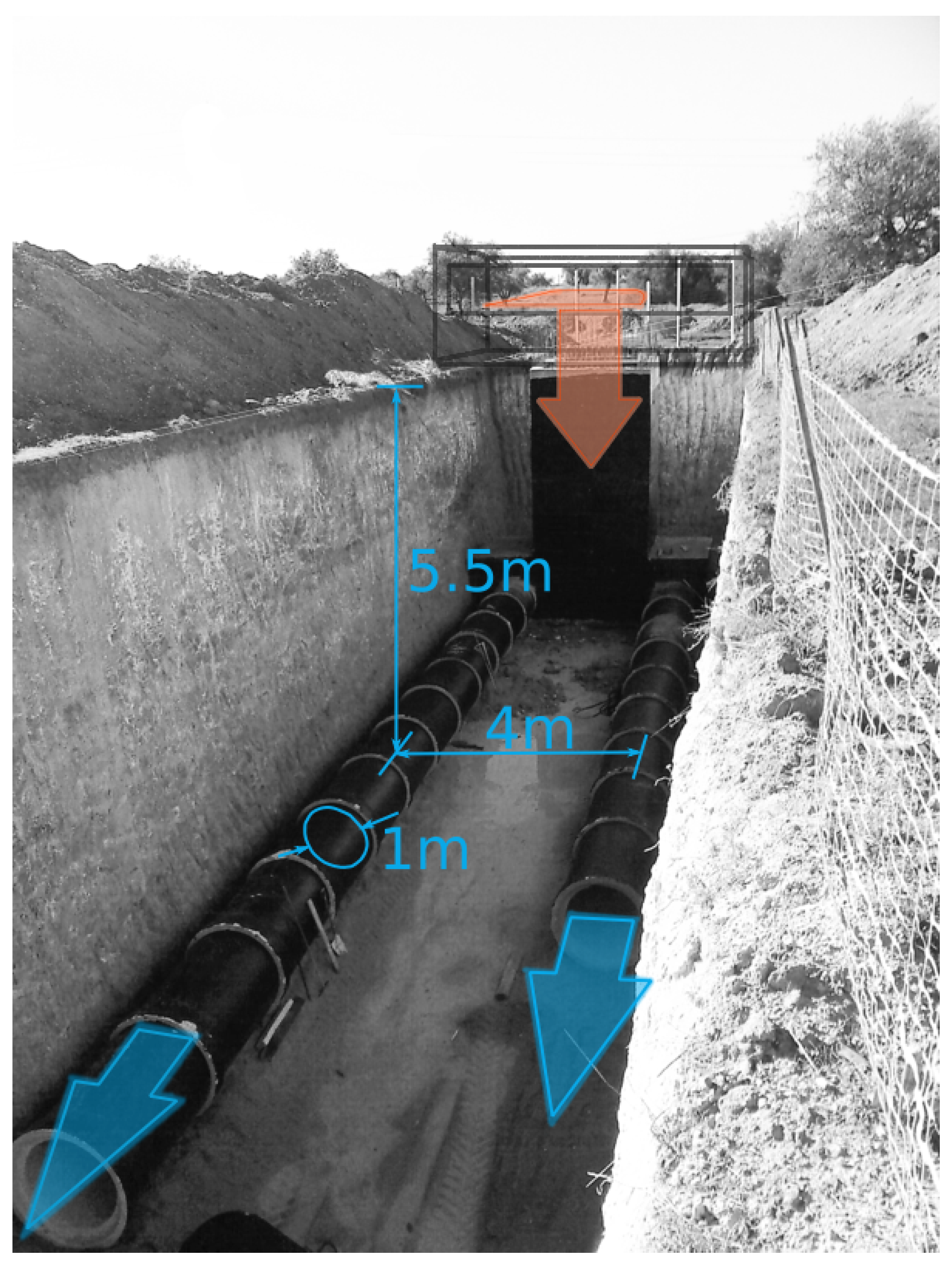
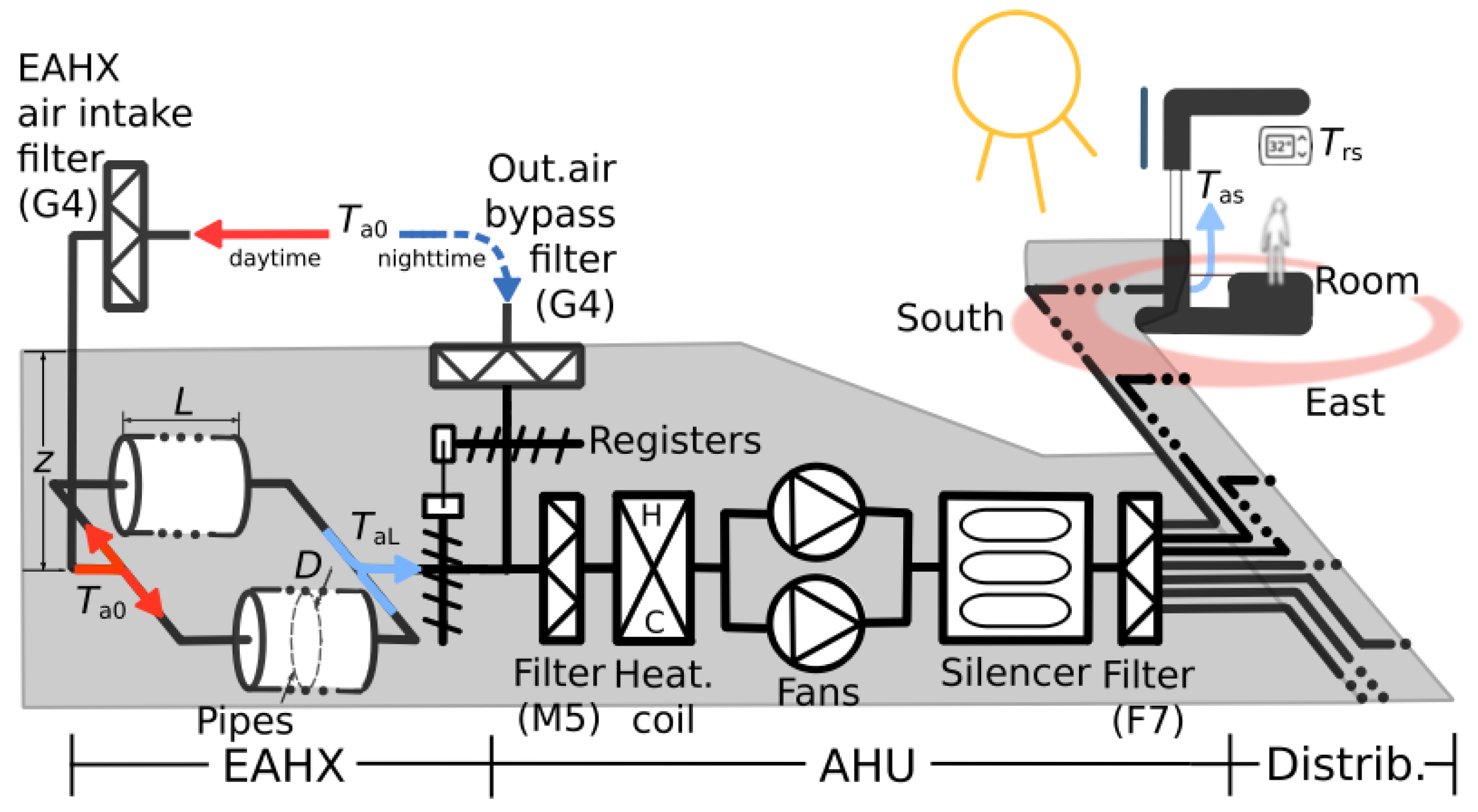
| Pipes | (a) The EAHX consists of two pipes (concrete) with 1 m diameter placed 4 m apart (distance between axes), 70 m long, buried 5.5 m deep (average depth, since pipes are sloped towards the air intake for water drainage). Water-resistant coatings prevent the transfer of water across the pipes towards/from the soil. The pipes’ inner surface coating has fungicidal and bactericidal properties to prevent the growth of mold and bacteria. |
| Air intake | (b) Outdoor air is admitted into the buried pipes at a technical space built above ground. A G4 filter [28] installed in this technical space prevents the intake of spores, pollen and coarse dust. |
| Vegetative cover | (c) To reduce soil surface temperature (during the summer period), species found in tallgrass prairies (e.g., Lolium perenne, Festuca arundinacea, Poa pratensis, Festuca rubra) were planted covering the ground above the EAHX. |
| Pressure loss | (d) Due to the large pipe diameter, pressure loss in the EAHX is related to the air intake filter, which, with its large surface and low face velocity, has negligible pressure loss compared to that in the AHU and in the distribution piping. |
| AHU | |
| Generic description | (e) In the direction of the airflow, the EAHX consists of a mixing chamber fitted with registers to allow for EAHX bypass with outdoor air (not used in this study), an M5 filter [28], a heating coil (not used in this study), two fans, a silencer and, prior to the air distribution to the rooms, a final F7 filter [28] for fine dust particles (1∼10 µm), preventing the distribution into rooms of bacteria and germs carried on host particles. As for the EAHX air intake, a coarse G4 filter is used at the bypass outdoor air intake. AHU dimensions were intentionally oversized to reduce pressure loss. |
| Fans | (f) To supply a nominal flowrate of 8000 m/h of air to the rooms, a redundant set of two electrically commutated plug fans (IE5) with 3.6 kW rated power each are used. |
| Pressure loss | (g) Design pressure loss in the AHU is 325 Pa. |
| Distribution piping | |
| Generic description | (h) Cooled air is distributed to the rooms using high-density polyethylene (HDPE) corrugated pipes with varying diameters (<0.40 m) laid along the south façade of the building. Pipes run inside a rectangular pathway, buried 3.0 to 1.5 m deep, made of cement (bottom) and cement blocks (side walls). This pathway is (inside) insulated with XPS (60 mm), limiting heat loss to the soil (through the sides and bottom). |
| Pressure loss | (i) Design pressure loss in the distribution piping is 375 Pa. |
| Diffusion of air and temperature control in the cooled rooms | |
| Generic ventilation strategy | (j) A 100% fresh air system. Forced (cooled) air is supplied to the rooms at the south façade and at the reception through linear air diffusers placed along the exterior wall at floor level. Air flows to corridors and from there to the outside, exiting the building behind the south façade photovoltaic panels. |
| Pressure loss | (k) Linear air diffusers’ specification is such that pressure loss associated with the introduction of supply air in the rooms is negligible compared to that in the AHU and in the distribution piping. |
| Temperature control | (l) Temperature control in the cooled rooms is achieved by varying the air-change rate. This control is limited by outdoor air conditions and by heat transfer with the soil. The control law depends (for hot and dry conditions) on room air and room setpoint temperatures, on EAHX exit air temperature, and on outdoor air temperature. To compensate for the system lower room-to-supply-air temperature gradients, large air-change rates are allowed [10,18]. Special attention is given to the specification of linear air diffusers so that larger airflow velocities in the room do not cause local discomfort with draught. |
| Temperature setpoint | (m) Adaptive comfort principles are assumed allowing free-floating room temperatures correlated to outdoor air temperatures. In other words, room setpoint temperature is allowed to vary and may be larger than setpoints typically associated with refrigeration machine cooling (>27 °C). |
| Nighttime ventilation | (n) Nighttime forced ventilation with cold outdoor air is used in two ways. Firstly, in combination with heavyweight building construction materials (insulated on the outside), making use of the walls’ and floor’s large thermal lag times to decrease room peak cooling requirements and decrease operative room temperatures. Secondly, in combination with the soil covering the insulated rectangular pathway for the distribution piping, allowing the use of the soil thermal mass to increase thermal lag times, contributing to additional daytime cooling of EAHX exit air. |
| Outdoor Air (Vaisala Weather Station [35]) | |
| Out.air temp.sensor, | Duration: 1 year. |
| Log.frequency: 1 min. | |
| Sensor location: Outdoor, ∼1.5 m above ground in a unobstructed area. | |
| Range: −53 to +60 °C. | |
| Accuracy: ±0.3 °C (at 20 °C). | |
| Out.air rel.hum.sensor, | Duration: 1 year. |
| Log.frequency: 1 min. | |
| Sensor location: Outdoor, ∼1.5 m above ground in a unobstructed area. | |
| Range: 0 to 100%. | |
| Accuracy: ±3% (from 0 to 90%); ±5% (from 90 to 100%). | |
| EAHX | |
| Exit air temp. sensor, (Onset datalogger [36]) | Duration: From 1 June to 30 September. |
| Log.frequency: 15 min. | |
| Sensor location: AHU mixing chamber. | |
| Range: −20 to +70 °C. | |
| Accuracy: ±0.35 °C (from 0 to 50 °C). | |
| Airflow rate, (Fan controller module [37] measuring airflow rate from fan diff.pressure) | Duration: From 1 June to 30 September. |
| Log.frequency: 15 min. | |
| Sensor location: AHU. | |
| Range: 0 to 1000 Pa. | |
| Accuracy: ±1.3% (max). | |
| June | July | August | September | Summer (June–September) | ||
|---|---|---|---|---|---|---|
| max. | 40.2 | 38.8 | 36.1 | 31.9 | 40.2 | |
| 29.3 | 31.1 | 28.2 | 24.7 | 28.3 | ||
| median | 23.6 | 25.7 | 23.5 | 20.5 | 23.3 | |
| 19.3 | 21.0 | 19.3 | 17.5 | 19.1 | ||
| min. | 11.5 | 14.9 | 14.4 | 11.3 | 11.3 | |
| max. | 93 | 88 | 90 | 92 | 93 | |
| 57 | 62 | 67 | 71 | 65 | ||
| median | 41 | 44 | 51 | 54 | 47 | |
| 26 | 28 | 36 | 39 | 32 | ||
| min. | 9 | 9 | 8 | 15 | 8 |
| max. | 31.9 | 29.9 | 25.9 | 23.9 |
| median | 30.8 | 28.8 | 24.8 | 22.8 |
| min. | 28.7 | 26.7 | 22.7 | 20.7 |
| June | July | August | September | Summer (June–September) | ||
|---|---|---|---|---|---|---|
| max. | 31.0 | 29.9 | 29.8 | 25.6 | 31.0 | |
| 25.4 | 26.7 | 25.5 | 22.6 | 25.4 | ||
| median | 23.0 | 24.4 | 23.7 | 21.1 | 23.3 | |
| 20.5 | 22.7 | 22.0 | 20.1 | 21.4 | ||
| min. | 16.0 | 20 | 19.3 | 17.6 | 16.0 | |
| max. | 10.9 | 9.1 | 9.2 | 7.1 | 10.9 | |
| 5.9 | 5.8 | 5.4 | 4.2 | 5.5 | ||
| a | median | 3.7 | 4.2 | 3.9 | 2.5 | 3.7 |
| 1.6 | 2.2 | 1.8 | 1.1 | 1.7 | ||
| min. | ∼0 | ∼0 | ∼0 | ∼0 | ∼0 |
Disclaimer/Publisher’s Note: The statements, opinions and data contained in all publications are solely those of the individual author(s) and contributor(s) and not of MDPI and/or the editor(s). MDPI and/or the editor(s) disclaim responsibility for any injury to people or property resulting from any ideas, methods, instructions or products referred to in the content. |
© 2023 by the authors. Licensee MDPI, Basel, Switzerland. This article is an open access article distributed under the terms and conditions of the Creative Commons Attribution (CC BY) license (https://creativecommons.org/licenses/by/4.0/).
Share and Cite
Duarte, R.; Gomes, M.d.G.; Moret Rodrigues, A.; Pimentel, F. A Large-Diameter Earth–Air Heat Exchanger (EAHX) Built for Standalone Office Room Cooling: Monitoring Results for Hot and Dry Summer Conditions. Appl. Sci. 2023, 13, 12134. https://doi.org/10.3390/app132212134
Duarte R, Gomes MdG, Moret Rodrigues A, Pimentel F. A Large-Diameter Earth–Air Heat Exchanger (EAHX) Built for Standalone Office Room Cooling: Monitoring Results for Hot and Dry Summer Conditions. Applied Sciences. 2023; 13(22):12134. https://doi.org/10.3390/app132212134
Chicago/Turabian StyleDuarte, Rogério, Maria da Glória Gomes, António Moret Rodrigues, and Fernando Pimentel. 2023. "A Large-Diameter Earth–Air Heat Exchanger (EAHX) Built for Standalone Office Room Cooling: Monitoring Results for Hot and Dry Summer Conditions" Applied Sciences 13, no. 22: 12134. https://doi.org/10.3390/app132212134
APA StyleDuarte, R., Gomes, M. d. G., Moret Rodrigues, A., & Pimentel, F. (2023). A Large-Diameter Earth–Air Heat Exchanger (EAHX) Built for Standalone Office Room Cooling: Monitoring Results for Hot and Dry Summer Conditions. Applied Sciences, 13(22), 12134. https://doi.org/10.3390/app132212134