Abstract
A new parameter estimation method for a UAV braking system with unknown friction parameters is suggested. The unknown part containing friction is separated from the coupling system. The law of parameter updating is driven by the estimation error extracted by the auxiliary filter. A controller is developed to guarantee the convergence of the parameter estimation and tracking errors simultaneously. Furthermore, a designed performance index function enables the system to track the desired slip rate optimally. The optimal value of the performance function is updated by a single critic neural network (NN) to obtain comprehensive optimization of the control energy consumption, dynamic tracking error, and filtering error during braking. In addition, the unknown bounded interference and neural network approximation errors are compensated by robust integral terms. Simulation results are presented to confirm the effectiveness of the proposed control scheme.
1. Introduction
With the rapid development of unmanned aerial vehicles (UAVs), the safety and efficiency of braking systems have drawn significant attention. Due to the coupling mechanism of vertical and longitudinal torques, the highly nonlinear aircraft dynamics model, and time-varying friction, it is challenging to establish an accurate mathematical model [1]. The most common control strategy for brake systems is slip rate control, which obtains the maximum tire–road friction by regulating the slip rate. Several methods have been proposed, such as dynamic surface control [2], adaptive control [3], and extreme value search control [4]. These methods focus on adjusting the slip rate in real time to track the expected slip rate but only partially consider an excellent dynamic performance and the system’s robustness. The ideal brake control should ensure that the brake operating point is always in the stable region. A rule-based control strategy has been studied in [5,6] to avoid the brake operating point being in an unstable region, which requires high model accuracy and has a complex controller structure. In [6], an adaptive radial basis function (RBF) neural network (NN) is used to predict the upper bound of the system’s complex external interference to improve the brake control’s robustness. The RBFNN and error backpropagation NN were used, respectively, to approximate the nonlinear interference of reduction gear deformation and switched reluctance motor in an Electro Mechanical Actuator (EMA) [7,8]. However, these models need to be trained offline in advance.
The friction coefficient affecting the binding force between the tire and runway in brake systems is influenced by external environments and various factors, making it challenging to measure directly or calculate accurately. Previous studies [9,10] proposed a fitting function between aircraft speed and slip rate. Still, this method requires a large amount of data for offline fitting and may not reflect the complex and changeable runway environment in real time and reduce control accuracy. Ref. [11] proposed the estimation of aircraft speed and ground–tire joint force based on the Kalman filter, but this requires additional sensors or algorithmic complexity, leading to practical difficulties. In addition, uncertain nonlinear systems with unmodeled dynamics can also be approximated by neural networks (NNs) [12,13,14] and fuzzy logic systems (FLSs) [15,16,17]. In these methods, the unknown friction is considered part of the nonlinearity of the unknown system and approximated by NN or FLS. Ref. [18] proposes an adaptive feedforward NN control scheme to deal with the pandybat friction effect, assuming that the friction model parameters are known. Moreover, traditional adaptive control design often adopts methods such as gradient [19], least squares [20], and the modified parameter estimation method [21]. However, none of the mentioned achieve convergence of the estimated parameters and tracking errors simultaneously. A new parameter estimation method [22] is proposed to ensure the convergence of parameters. In the controller design, the adaptive rate based on the parameter estimation method ensures that the unknown parameter converges to the true value and the tracking error converges to zero.
Moreover, as the balance criterion of resource control and control effect plays an increasingly important role in the design process, optimal control has attracted wide attention [23,24,25,26,27]. At present, the optimal control theory related to the design of the controller has been a significant research result. It can meet the tracking tasks or control objectives, while minimizing some performance indicators. In the classical optimal control method, the derived Riccati or Hamilton–Jacobi–Bellman (HJB) equation is usually solved offline iteratively [28]. In recent years, adaptive dynamic programming (ADP) has been proven to be a feasible method to solve the optimal control solution online [29]. In the classical critic–actor-based ADP framework [30], the complex ADP structure of multiple NN approximators increases the computational burden in the implementation. Thus, a simple and effective ADP structure based on a single critic NN is proposed in [31,32], in which the convergence of critic NN weight can be retained so that control actions can be calculated directly through the weight of a critic NN. Due to the fact that the approximate error of the NN cannot be compensated for, the steady-state error can only be guaranteed to converge to a small set near zero. A new error sign robust integral (RISE) control is developed in [33] to compensate for bounded uncertainties and perturbations. The key feature of the RISE method is that asymptotic stability can be proved by using an integral of the sign of the error feedback term. In addition, compared with the traditional Sliding Mode Control (SMC) method [34], this scheme generates continuous control signals, thus avoiding the requirement of infinitely fast control switching.
Motivated by the above discussions, the aim of this article is to develop a new adaptive law to ensure convergence of estimation parameters and tracking errors in UAV braking systems. A performance index function of error and input is established for the braking system, considering the balance criterion of control resources and control effect, and the optimal solution is updated online with ADP. Moreover, the improved adaptive optimal control strategy includes robust feedback items. Their purpose is to compensate bounded disturbance, modeling uncertainty, and NN estimation error, minimizing the cost function while tracking slip rate, reducing the use of control resources, and improving control performance. Comparative simulations are given to validate the effectiveness.
The contributions of this paper are as follows.
- (1)
- A parameter-updating law driven by parameter estimation error is designed for UAV braking systems with unknown parameters. The contradiction between system robustness and parameter convergence is solved, and the tracking error and estimation error converge simultaneously.
- (2)
- The performance index function about the error and input of the UAV braking system is established. The adaptive dynamic programming based on a single critic NN is adopted to solve the function so that the control energy consumption, dynamic tracking error, and filtering error in the braking process are optimized comprehensively.
2. Dynamic Model
Braking Dynamics of UAV
The dynamics model of the UAV braking system generally includes the body dynamics model, braking wheel dynamics model, tire–runway friction, and brake actuator. Brake control design should be based on a reasonable and simplified mathematical model. According to [35], consider the system formulated as
where and are unknown bounded disturbances. The above parameters are described in Table 1. The slip rate in the system is defined as

Table 1.
Parameters of UAV and EMA.
The slip rate represents the ratio of the sliding motion of the wheel to the runway; thus, . The braking process depends on the binding force between the brake wheel and the ground, which is defined as
It is affected by many factors and cannot be directly measured or accurately calculated.
We define the state of the system as , and then the system is described as
where , , , , , and are positive constants.
Rewrite the derivative of in (4) as , where is the unknown parameter vector, and is the known regressor vector.
Let be the expected slip rate set, and define the tracking error as
Assumption 1.
The perturbation and its derivatives , and are bounded.
Assumption 2.
Linear velocity , angular velocity of the wheel ω, brake pressure , motor speed , and armature current i can be measured.
The problems to be solved in this paper are as follows:
- Online estimation of unknown parameters of UAV braking system to ensure convergence.
- When , tracking errors converge quickly and steady-state tracking errors remain within a small range.
- The system control input and filtering error meet the performance function.
3. Adaptive Optimal Control Design with Guaranteed Parameter Estimation
This section proposes an adaptive optimal control based on the parameter estimation error for the system (4). We will introduce a new adaptive law driven by the estimation error to estimate unknown parameters and an optimal control item for minimizing performance function. The control structure is shown in Figure 1.
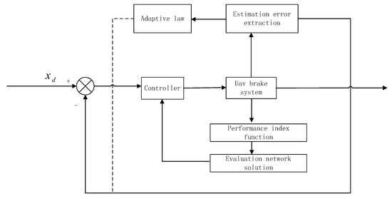
Figure 1.
Structure of the control system.
3.1. Filter Design
The traditional adaptive control derives the adaptive law through the gradient algorithm and least square method to minimize tracking error, but the robustness is poor. Based on the previous research, an auxiliary filter is used to extract the parameter estimation error and drive parameter updating to obtain a better-estimated response [36].
To facilitate the design of the adaptive law, the first equation in (4) is considered:
where is the unknown parameter vector, is a known nonlinear function matrix, and is a known nonlinear. The filtered variables and , of the dynamics and , F are defined as [22]
where ∂ is a filter constant. Then it is obtained from (6) and (7) that
and
The matrix G and vector Q are defined as
where is a design parameter. The solution of (9) is derived as
Then, another auxiliary variable H is defined as
where the estimation of the unknown parameter is . Substituting (8) into (10), one has
where is defined as the estimation error.
3.2. Adaptive Control with Finite-Time Parameter Estimation
For the position tracking control, we define filter tracking error variables as
where and are positive constants, and is the auxiliary filter error.
From (4), (5), (6), (13), (14), one has
will be regarded as virtual input, the design virtual control rate is , and we define the input error as
In order to reduce the impact of noise in measurement, the expected trajectory is used to replace , so can be rewritten by using the expected trajectory as
where the auxiliary function is
The design virtual control rate is
where is the feedback item of RISE and
The time derivative of is
where is a positive feedback gain, is a positive constant, and is a function of signum. The extracted estimation error is added to the traditional adaptive law. This method makes the error of parameter estimation and system control converge eventually.
The parameter-updating law of is
with
where is the regressor and are the learning gains. Since is not to directly implement online learning, inspired by [37], we write (22) in the following form:
As follows from (24), the variables can be replaced by , where the Newton–Leibniz formula is used to calculate . Therefore, the parameters can be calculated according to (24). The auxiliary filtering signal is designed as
The error variable combined with (4), (16), and (25) can be rewritten by using the desired trajectory and as
where the auxiliary function is
The brake control effect is also affected by brake performance. Thus, torque and energy consumption need to be considered in the brake control system, to realize efficient and stable control of the aircraft brake. According to (26), the controller is
where is the auxiliary optimal controller for the given secondary performance index of the system and is the feedback item of RISE with
The time derivative of is
where are normal numbers.
3.3. Optimal Control Auxiliary Item Design
Considering the optimal synthesis of control energy consumption, dynamic tracking error, and filtering error, we design the performance index functions for the following dynamic error closed-loop system of the system, which can be obtained from (4) and (16) such that
By substituting controller (28) into (31), the dynamic equation of filtering error is
where denotes the lumped disturbances and compensation error. The cost function for the system (32) is designed as
According to Bellman’s optimality principle [38], the solution of the optimal cost function is the solution of the HJB equation:
And the optimal control solution can be obtained as
where , and it is a necessary condition for solving the optimal control, which is approximated by NN:
where and are the optimal weight and activation function of the evaluation NN, and represents the approximate error that converges to zero after proper training under continuous excitation. In practice, the ideal NN weights W are unknown, combined with (36) and (37); thus, we have the actual optimal control as
In order to make the weight estimation of the NN converge quickly to the ideal value, the control mode of parameter updating is driven by the extraction estimation error in (13)–(21). This mode avoids using an executive NN, which significantly reduces the amount of training computation, speeds up the weight convergence, and improves the estimation accuracy. In order to determine the critical NN weight, the HJB equation can be expressed as
where is a bounded error caused by the approximation error of critic NN, model linearization error, and system uncertainty. Suppose ; we obtain
where is a utility function. We define regression matrix A and regression vector B. One has
where the regression parameter l is the normal number. The auxiliary vector based on A and B is introduced as
According to (19)–(21), we obtain
where is the estimation error. We have for . is the weight error, which is related to the auxiliary vector . The designed update rule is
where is learning gain, and the calculation of is the same as (24).
4. Stability and Convergence Analysis
To analyze the stability of the closed-loop system, we obtain by (28) and (22) as
where
The auxiliary function is
Let . Substituting control law (35) and (43) into (26), the closed-loop system can be written as
The time derivative of is
where
The auxiliary function is
Lemma 1
([2]). Define the following two auxiliary functions for the convenience of analysis:
where , meet the following conditions:
where , , , and are positive constants, and the following defined functions , are always positive:
Select a Lyapunov function candidate as
Let us define a vector
where
The Lyapunov function satisfies the inequality
The continuous, positive definite functions and are defined as
where are positive constants. We substitute (5), (13), (16), (22,) (43), (44), (48), (55), and (56) into the derivative of . It follows that
Using the Young’s inequality, one has
where ρ is the function of , and it may have a constant term, a first term, a second term, or a higher term.
It is shown that the proposed NN weight estimation method can make the error converge to zero exponentially, and the convergence is determined by continuous excitation and learning rate. Substitute (64), (65), (66) into (63) to obtain
where is a positive constant, and is a continuous positive function over a set defined as
Therefore, inequalities (67) and (68) can be used to prove above Ξ, which further implies that in . in can be proven through . Meanwhile, the fact that and are bounded implies that , given that in . A similar analysis to that given in [39] can prove that in . Then, we can also verify that . The is uniformly continuous in due to in Ξ. Hence, we can verify that by an analysis similar to that shown in [36]. Then, from the definition of r,,, we can obtain that for , and the proof of convergence of parameter estimation error can be seen [1].
5. Simulations
In order to verify the effectiveness of the proposed control law, simulation tests are carried out on the MATLAB platform with the model parameters in [35]. The reference slip rate is set as 0.1, the initial landing velocity m/s, and the initial main wheel angular velocity rad/s, and the initial slip rate is set as .
The parameters in the controller are designed to , , , , = 1, , , and the critic NN weights converge to [−1.982, −1.553, −4.006, −3.86, −1.210, −0.567, 0.72, −0.9234, −0.34, 0.765, 1.076, 0.365, 3.023].
The changes in the speed and distance of the UAV during braking are shown in Figure 2 and Figure 3. It takes 21.6 s from the start of braking to the end of the anti-skid control, and the braking distance is 702.5 m. No significant overshoot occurs during the braking process, and the velocity and wheel speed decrease smoothly without large fluctuations or deep skid of the wheel.
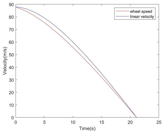
Figure 2.
Aircraft speed and wheel speed.
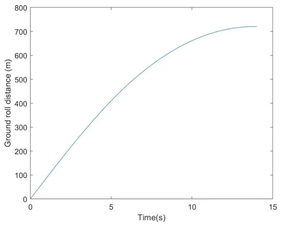
Figure 3.
Stopping distance.
It can be seen from Figure 4 that the controller can track the optimal slip rate of real-time changes quickly and accurately and is always in the stable region. Figure 5 shows that the tracking error of the optimized controller based on RISE correction converges asymptotically to zero, meeting the high-precision requirements compared to the generic control with the gradient algorithm.
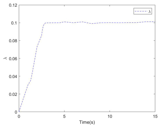
Figure 4.
Wheel slip ratio.
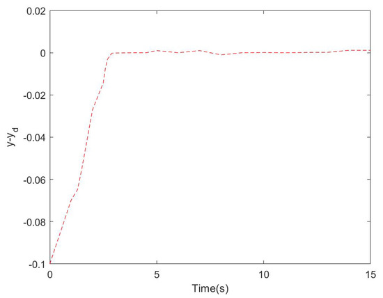
Figure 5.
The tracking error.
To show the improved estimation and control performance, the method proposed in this paper is shown in Figure 6. Compared with the conventional control algorithm shown in Figure 7, the parameter estimation error can converge to zero and the convergence speed is fast.
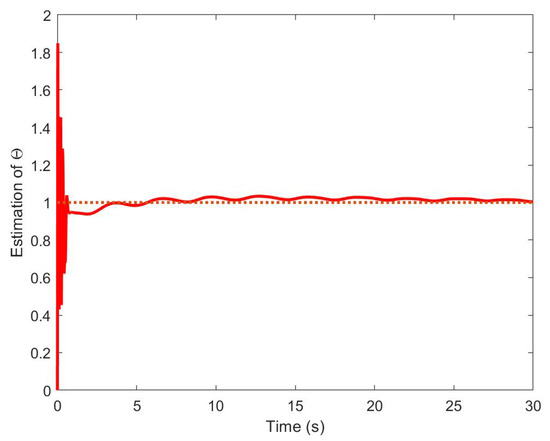
Figure 6.
Textual method.
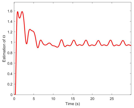
Figure 7.
Gradient descent.
The quadratic performance index function of the algorithm is designed in this paper and the conventional algorithm is estimated by MATLAB. The performance index function of the optimized controller is larger than that of the conventional controller, which indicates that the RISE-modified adaptive optimal controller ensures the comprehensive quasi-optimal of the system dynamic error and control energy consumption during the whole braking process. The control input is shown in Figure 8.
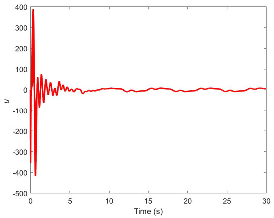
Figure 8.
Gradient descent.
Figure 9 shows the estimated weight of the NN. It can be seen that the weights converge to constant values. This result shows the convergence of the adaptive law and verifies the effectiveness of the proposed learning algorithm.
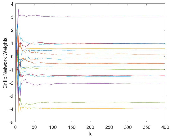
Figure 9.
The control input.
To show the improved performance of the proposed single critic NN-based ADP, compared with a critic–actor NN-based ADP method mentioned in [31], it is clear that the proposed single critic NN-based can achieve faster transient error convergence and smaller steady-state tracking errors.
The simulation results show that the designed controller has a good control effect, realizes the tracking of the unknown optimal slip rate, and has a robust ability. By comparing the size of the secondary performance index, the modified optimized controller can meet the performance index, and the system’s control input and control error are optimized comprehensively.
6. Conclusions
This paper investigated unknown parameter estimation for the UAV brake system and tracked the optimal slip rate at minimum cost. Parameter estimation error is extracted by an auxiliary filter and drives a parameter-updating law incorporated into adaptive control synthesis. Compared with traditional estimation methods, this method can simultaneously guarantee the convergence of parameter estimation and track errors. A performance index function of control input and filtering error was designed, considering the balance of control resources and control effect. This paper made up for the lack of consideration of resource control in the previous literature on UAV brake systems. Based on the ADP idea, an NN was introduced to approximate the performance index function online, and an adaptive law was designed to update the NN weights and optimal control online. Simulation results prove that the proposed single critic NN-based method can achieve faster transient error convergence and smaller steady-state tracking errors. Through theoretical and simulation analysis, the modified controller can converge to the optimal controller, compensating for external perturbations, modeling uncertainties, and NN estimation errors by combining the principles of adaptive control and optimal control with the RISE robust term.
Author Contributions
Conceptualization, X.G. and H.L.; methodology, Q.L. and H.L.; software, Y.W.; validation, Y.W., F.L. and Z.L.; formal analysis, Q.L.; invetigation, H.L.; data curation, F.L.; writing—original draft preparation, H.L.; writing—review and editing, X.G.; visualization, Y.W.; funding acquisition, X.G. All authors have read and agreed to the published version of the manuscript.
Funding
This research received no external funding.
Institutional Review Board Statement
Not applicable.
Informed Consent Statement
Not applicable.
Data Availability Statement
The data that support the findings of this study are available from the corresponding author upon reasonable request. The data are not publicly available due to privacy or ethical restrictions.
Conflicts of Interest
The authors declare no conflict of interest.
References
- Hoseinnezhad, R.; Bab-Hadiashar, A. Efficient Antilock Braking by Direct Maximization of Tire–Road Frictions. IEEE Trans. Ind. Electron. 2011, 58, 3593–3600. [Google Scholar] [CrossRef]
- Peng, Z.; Jiang, Y.; Wang, J. Event-Triggered Dynamic Surface Control of an Underactuated Autonomous Surface Vehicle for Target Enclosing. IEEE Trans. Ind. Electron. 2021, 68, 3402–3412. [Google Scholar] [CrossRef]
- Hu, J.; Zheng, M. Disturbance observer-based control with adaptive neural network for unknown nonlinear system. Meas. Control 2022, 56, 287–294. [Google Scholar] [CrossRef]
- Dinçmen, E.; Güvenç, B.A.; Acarman, T. Extremum-Seeking Control of ABS Braking in Road Vehicles with Lateral Force Improvement. IEEE Trans. Control Syst. Technol. 2014, 22, 230–237. [Google Scholar] [CrossRef]
- Capra, D.; Galvagno, E.; Ondrak, V.; van Leeuwen, B.; Vigliani, A. An ABS control logic based on wheel force measurement. Veh. Syst. Dyn. 2012, 50, 1779–1796. [Google Scholar] [CrossRef][Green Version]
- Pasillas-Lépine, W. Hybrid modeling and limit cycle analysis for a class of five-phase anti-lock brake algorithms. Veh. Syst. Dyn. 2006, 44, 173–188. [Google Scholar] [CrossRef]
- Zhang, Y.X.; Lin, C.P. Backstepping Adaptive Neural Network Control for Electric Braking Systems of Aircrafts. Algorithms 2019, 12, 215. [Google Scholar] [CrossRef]
- Chen, H.; Zhang, X.; Xu, Y. Modeling, Simulation, and Experiment of Switched Reluctance Ocean Current Generator System. Adv. Mech. Eng. 2013, 5, 261241. [Google Scholar] [CrossRef]
- Yi, J.; Alvarez, L.; Horowitz, R. Adaptive emergency braking control with underestimation of friction coefficient. IEEE Trans. Control. Syst. Technol. 2002, 10, 381–392. [Google Scholar] [CrossRef]
- Braghin, F.; Cheli, F.; Sabbioni, E. Environmental effects on Pacejka’s scaling factors. Veh. Syst. Dyn. 2006, 44, 547–568. [Google Scholar] [CrossRef]
- Jiao, Z.; Liu, X.; Shang, Y.; Huang, C. An integrated self-energized brake system for aircrafts based on a switching valve control. Aerosp. Sci. Technol. 2017, 60, 20–30. [Google Scholar] [CrossRef]
- Xu, B.; Yang, D.; Shi, Z.; Pan, Y.; Chen, B.; Sun, F. Online Recorded Data-Based Composite Neural Control of Strict-Feedback Systems with Application to Hypersonic Flight Dynamics. IEEE Trans. Neural Netw. Learn. Syst. 2018, 29, 3839–3849. [Google Scholar] [CrossRef]
- Gao, H.; He, W.; Zhou, C.; Sun, C. Neural Network Control of a Two-Link Flexible Robotic Manipulator Using Assumed Mode Method. IEEE Trans. Ind. Inform. 2019, 15, 755–765. [Google Scholar] [CrossRef]
- Wang, S.; Yu, H.; Yu, J.; Na, J.; Ren, X. Neural-Network-Based Adaptive Funnel Control for Servo Mechanisms with Unknown Dead-Zone. IEEE Trans. Cybern. 2020, 50, 1383–1394. [Google Scholar] [CrossRef]
- Liu, Y.J.; Tong, S.; Chen, C.L.P. Adaptive Fuzzy Control via Observer Design for Uncertain Nonlinear Systems with Unmodeled Dynamics. IEEE Trans. Fuzzy Syst. 2013, 21, 275–288. [Google Scholar] [CrossRef]
- Tong, S.; Zhang, L.; Li, Y. Observed-Based Adaptive Fuzzy Decentralized Tracking Control for Switched Uncertain Nonlinear Large-Scale Systems With Dead Zones. IEEE Trans. Syst. Man Cybern. Syst. 2016, 46, 37–47. [Google Scholar] [CrossRef]
- Li, Z.; Xiao, S.; Ge, S.S.; Su, H. Constrained Multilegged Robot System Modeling and Fuzzy Control with Uncertain Kinematics and Dynamics Incorporating Foot Force Optimization. IEEE Trans. Syst. Man Cybern. Syst. 2016, 46, 1–15. [Google Scholar] [CrossRef]
- Xia, D.; Wang, L.; Chai, T. Neural-Network-Friction Compensation-Based Energy Swing-Up Control of Pendubot. IEEE Trans. Ind. Electron. 2014, 61, 1411–1423. [Google Scholar] [CrossRef]
- Sastry, S.; Bodson, M. Adaptive Control: Stability, Convergence and Robustness. J. Acoust. Soc. Am. 1990, 88, 588–589. [Google Scholar] [CrossRef]
- Narendra, K.S.; Annaswamy, A.M.J.P.H. Stable Adaptive Systems; Prentice Hall: Hoboken, NJ, USA, 1989. [Google Scholar]
- Ioannou, P.; Sun, J. Robust Adaptive Control; PTR Prentice-Hall: Upper Saddle River, NJ, USA, 1995. [Google Scholar]
- Na, J.; Herrmann, G.; Ren, X.; Mahyuddin, M.N.; Barber, P. Robust adaptive finite-time parameter estimation and control of nonlinear systems. In Proceedings of the 2011 IEEE International Symposium on Intelligent Control, Denver, CO, USA, 28–30 September 2011; pp. 1014–1019. [Google Scholar] [CrossRef]
- Yang, X.; Liu, D.; Wang, D. Reinforcement learning for adaptive optimal control of unknown continuous-time nonlinear systems with input constraints. Int. J. Control 2013, 87, 553–566. [Google Scholar] [CrossRef]
- Liu, D.; Wang, D.; Wang, F.Y.; Li, H.; Yang, X. Neural-Network-Based Online HJB Solution for Optimal Robust Guaranteed Cost Control of Continuous-Time Uncertain Nonlinear Systems. IEEE Trans. Cybern. 2014, 44, 2834–2847. [Google Scholar] [CrossRef]
- Peng, Z.; Luo, R.; Hu, J.; Shi, K.; Nguang, S.K.; Ghosh, B.K. Optimal Tracking Control of Nonlinear Multiagent Systems Using Internal Reinforce Q-Learning. IEEE Trans. Neural Netw. Learn. Syst. 2022, 33, 4043–4055. [Google Scholar] [CrossRef] [PubMed]
- Peng, Z.; Zhao, Y.; Hu, J.; Luo, R.; Ghosh, B.; Nguang, S. Input-Output Data-Based Output Antisynchronization Control of Multi-Agent Systems Using Reinforcement Learning Approach. IEEE Trans. Ind. Inform. 2021, 17, 7359–7367. [Google Scholar] [CrossRef]
- Ding, L.; Li, S.; Gao, H.; Liu, Y.J.; Huang, L.; Deng, Z. Adaptive Neural Network-Based Finite-Time Online Optimal Tracking Control of the Nonlinear System With Dead Zone. IEEE Trans. Cybern. 2021, 51, 382–392. [Google Scholar] [CrossRef] [PubMed]
- Allwright, J. A lower bound for the solution of the algebraic Riccati equation of optimal control and a geometric convergence rate for the Kleinman algorithm. IEEE Trans. Autom. Control 1980, 25, 826–829. [Google Scholar] [CrossRef]
- Jiang, H.; Zhang, H.; Xie, X.; Han, J. Neural-network-based learning algorithms for cooperative games of discrete-time multi-player systems with control constraints via adaptive dynamic programming. Neurocomputing 2019, 344, 13–19. [Google Scholar] [CrossRef]
- Lewis, F.L.; Vrabie, D. Reinforcement learning and adaptive dynamic programming for feedback control. IEEE Circuits Syst. Mag. 2009, 9, 32–50. [Google Scholar] [CrossRef]
- Na, J.; Herrmann, G. Online Adaptive Approximate Optimal Tracking Control with Simplified Dual Approximation Structure for Continuous-time Unknown Nonlinear Systems. IEEE/CAA J. Autom. Sin. 2014, 1, 412–422. [Google Scholar]
- Dong, H.; Zhao, X.; Luo, B. Optimal Tracking Control for Uncertain Nonlinear Systems with Prescribed Performance via Critic-Only ADP. IEEE Trans. Syst. Man Cybern. Syst. 2022, 52, 561–573. [Google Scholar] [CrossRef]
- Xian, B.; Dawson, D.M.; De Queiroz, M.S.; Chen, J. A continuous asymptotic tracking control strategy for uncertain multi-input nonlinear systems. In Proceedings of the 2003 IEEE International Symposium on Intelligent Control, Houston, TX, USA, 5–8 October 2003; pp. 52–57. [Google Scholar] [CrossRef]
- Shuzhi, S.G.; Hang, C.C.; Woon, L.C. Adaptive neural network control of robot manipulators in task space. IEEE Trans. Ind. Electron. 1997, 44, 746–752. [Google Scholar] [CrossRef]
- Chen, X.; Dai, Z.; Lin, H.; Qiu, Y.; Liang, X. Asymmetric Barrier Lyapunov Function-Based Wheel Slip Control for Antilock Braking System. Int. J. Aerosp. Eng. 2015, 2015, 917807. [Google Scholar] [CrossRef]
- Wang, S.; Na, J. Parameter Estimation and Adaptive Control for Servo Mechanisms With Friction Compensation. IEEE Trans. Ind. Inform. 2020, 16, 6816–6825. [Google Scholar] [CrossRef]
- Sharma, N.; Bhasin, S.; Wang, Q.; Dixon, W.E. RISE-Based Adaptive Control of a Control Affine Uncertain Nonlinear System With Unknown State Delays. IEEE Trans. Autom. Control 2012, 57, 255–259. [Google Scholar] [CrossRef]
- Bellman, R. On the Theory of Dynamic Programming. Proc. Natl. Acad. Sci. USA 1952, 38 8, 716–719. [Google Scholar] [CrossRef]
- Makkar, C.; Hu, G.; Sawyer, W.G.; Dixon, W.E. Lyapunov-Based Tracking Control in the Presence of Uncertain Nonlinear Parameterizable Friction. IEEE Trans. Autom. Control 2007, 52, 1988–1994. [Google Scholar] [CrossRef]
Disclaimer/Publisher’s Note: The statements, opinions and data contained in all publications are solely those of the individual author(s) and contributor(s) and not of MDPI and/or the editor(s). MDPI and/or the editor(s) disclaim responsibility for any injury to people or property resulting from any ideas, methods, instructions or products referred to in the content. |
© 2023 by the authors. Licensee MDPI, Basel, Switzerland. This article is an open access article distributed under the terms and conditions of the Creative Commons Attribution (CC BY) license (https://creativecommons.org/licenses/by/4.0/).