Article

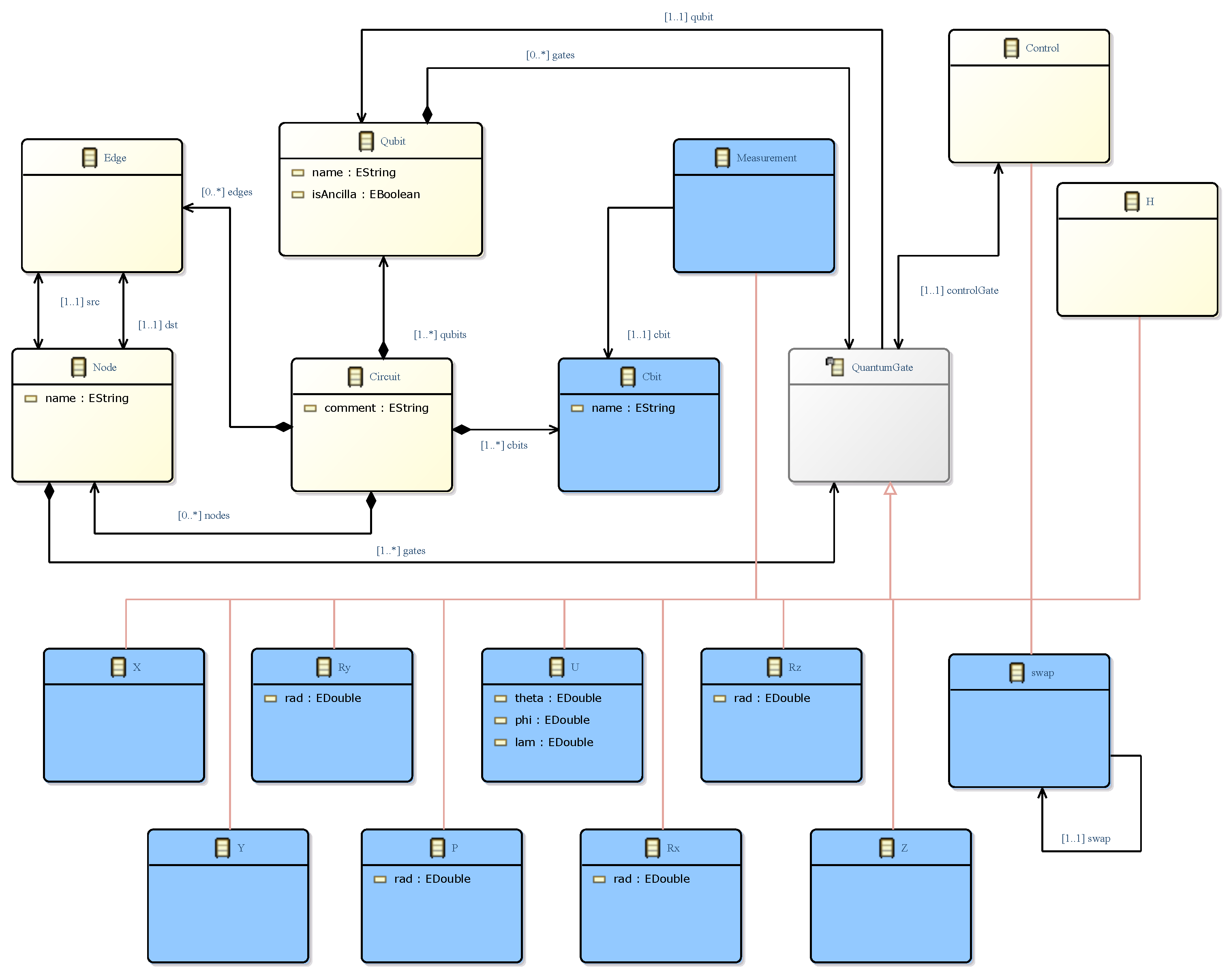
A Graph-Based Approach for Modelling Quantum Circuits

Department of Information and Communication Technologies, Universidad Politécnica de Cartagena, 30202 Cartagena, Spain
*
Author to whom correspondence should be addressed.
Appl. Sci. 2023, 13(21), 11794; https://doi.org/10.3390/app132111794
Submission received: 12 September 2023 / Revised: 21 October 2023 / Accepted: 23 October 2023 / Published: 28 October 2023
(This article belongs to the Special Issue Latest Research in Quantum Computing)

Abstract

:
A crucial task for the systematic application of model-driven engineering techniques in the development of quantum software is the definition of metamodels, as a first step towards automatic code generation and integration with other tools. The importance is even greater when considering recent work where the first extensions to UML for modelling quantum circuits are emerging and the characterisation of these extensions in terms of their suitability for a model-driven approach becomes unavoidable. After reviewing the related work, this article proposes a unified metamodel for modelling quantum circuits, together with five strategies for its use and some examples of its application. The article also provides a set of constraints for using the identified strategies, a set of procedures for transforming the models between the strategies, and an analysis of the suitability of each strategy for performing common tasks in a model-driven quantum software development environment. All of these resources will enable the quantum software community to speak the same language and use the same set of abstractions, which are key to furthering the development of tools to be built as part of future model-driven quantum software development frameworks.

1. Introduction

In their seminal article, Paul Benioff [1] described an implementation of a Turing machine by using Quantum Mechanics effects, while Richard Feynman [2] subsequently suggested that quantum computers could outperform classical (electronic) computers in performing some types of computation, in particular, the simulation of physical systems. These two articles launched the new field of Quantum Computing (QC) in Computer Science, which finally attracted the world’s attention following the publication of an article by Peter Shor [3], describing a quantum algorithm that could factorize prime numbers (and thus break RSA encryption) in Θ ( log 3 ( N ) ) , and an article by Lov Grover [4], describing a quantum algorithm for searching in an unordered data set in Θ ( N ) . Since these articles were published, the development of QC has experienced incredible growth, both in theory and in practice. Given the new computing power offered by computers that can exploit quantum mechanical effects to execute the aforementioned (and other) quantum algorithms, the applications of QC are almost endless [5]: economics, privacy, chemistry, physics, logistics, energy, artificial intelligence, optimization, machine learning, and medicine, among others.
Quantum software development has experienced spectacular growth in recent years thanks to the reality of quantum computers and the improvements in their computing power. For the first time in the recent history of computing, there are two coexisting computing models: classical computing and quantum computing, both based on different physical principles. Each has its own rules and characteristics, its own set of guiding principles and basic computing units to develop programs that solve real-world problems. Regardless of the enormous differences that exist in the hardware needed to run a program and the abstractions that support software development in each computing model, it is the task of the Software Engineering discipline to support each of them with techniques, methodologies and tools, based on knowledge acquired since the 1960s [5,6], to ensure that the software developed meets requirements regarding functionality, quality, time and budget.
There are several models of quantum computation (see [7] for an in-depth review) tailored in some cases to specific hardware technologies. But all of them share a common thread in that they allow the user to develop quantum software that exploits the unique effects of quantum mechanics, superposition and entanglement, to develop quantum algorithms that can achieve exponential speedups in solving some problems compared to the performance of their classical counter-parts (i.e., those running in digital computers). A quantum system consisting of ‘n’ qubits is described by a 2 n -dimensional Hilbert space. When a qubit is superposed, its state is modelled as a linear combination of the basis states | 0 and | 1 , and thus the state of the system is no longer unique, but is rather a combination of the individual states of the system’s qubits. The second effect, entanglement, implies that the state of the system can no longer be described as a combination of the individual states of the qubits, but that only the state of the group of qubits as a whole exists.
Among the available models of QC, this paper focuses on the Unitary Circuit Model [8], given its wide spread usage in the QC community (it is the one employed by major QC providers, such as IBM) and its generality (it is also Turing-complete [8]). This quantum circuit is one of the best-known models for quantum computing in which, like classical circuits, a computation is modelled as a sequence of quantum gates operating on qubits.
More recently, the Software Engineering community, and particularly within the discipline Software Language Engineering, is taking the first steps towards applying systematic, disciplined, and quantifiable approaches to the development, use, and maintenance of quantum software languages. The integration of solutions in the nascent field of model-driven quantum software development together with utilities for model-to-model transformations, is essential to support the adoption of the new computing paradigm.
The definition of ontologies for QC, the development of cross-platform compilers as well as reverse engineering facilities to extract models from already implemented solutions will be the focus of particular attention in the coming years in Software Engineering, as evidenced by recent work where some researchers are demonstrating that this is the effective approach to develop quantum software in a systematic and disciplined manner.
The development of a metamodel for quantum circuits and its integration into a Model-Driven Engineering process offers several significant advantages [9], such as (i) models can be reused across projects, reducing duplication of effort, (ii) automatic code generation from models to quantum programming frameworks, such as Qiskit, streamlines the implementation process, (iii) model-based analysis and validation helps identify errors and optimizations early on, and (iv) integration with existing tools leverages their capabilities for modelling, analysis, and code generation, improving the efficiency and quality of quantum circuit designs.
In this context, this paper reflects on modelling abstractions for the unitary circuit model of QC, given the results available in the literature and the structure and behaviour of said computational model. We describe a unified metamodel that supports at least five modelling strategies that cover the practices identified in the related work. We also provide a deep study of said metamodel by (i) providing OCL constraints that check whether models are valid, (ii) providing OCL query functions to identify the modelling strategy employed by a model, (iii) outlining model-to-model transformations between the strategies, (iv) outlining a model transformation to reduce the number of modelling elements required to model a quantum circuit, and (v) providing an OCL query function to identify whether said transformation has been applied to a model.
From the perspective of the usefulness for the creation of new metamodels, the identification of the strategies presented in this work, together with their suitability for performing model manipulations (navigation, transformations, etc.), should serve as a guide for developers to choose one strategy over others, and to make this decision before starting to develop the different tools. Our aim is to contribute with a single metamodel that can accommodate and make different ways of modelling quantum circuits compatible, so that the QC community can “speak and understand” the same language, while at the same time supporting some local variations.
The rest of this paper is organized as follows. Section 2 outlines the related work of applying model-driven engineering techniques to QC. Section 3 describes the main characteristics of the unitary circuit model for QC that are needed to understand it and that justify the metamodel proposed in this paper. Section 4 describes the proposed metamodel, together with five approaches in which it can be employed to model quantum circuits and an example problem that shows the feasibility of the proposal. Section 5 describes the constraints and model transformations mentioned above, which complete the proposal for a core set of tools to model quantum circuits. Section 6 is devoted to further discussion of the properties and suitability of each modelling strategy performing usual tasks in a model-driven development environment, such as editing models and developing model transformations. There is also a discussion of other aspects related to the work being presented, such as the role of domain-specific languages, the integration of the proposal into a hybrid classical–quantum development environment, as well as the applicability of the proposed approach to other quantum computing models. Lastly, concluding remarks are given in Section 7.

2. Related Work

The contribution of the Model-Driven Engineering (MDE) approach [10] to software construction over the last 20 years is undoubted, mainly in terms of productivity improvement both by increasing the value of the software artefact and by increasing the expectation of use [11]. These models embed simplified versions of the represented reality where some details are hidden or removed because they are irrelevant from a given perspective or for a given purpose. These models are therefore independent of the language and programming paradigm that will subsequently be used to translate them into code.
Moreover, thanks to these models, knowledge sharing between technical and non-technical staff is made easier by facilitating the use of concepts close to the problem domain. Accuracy, predictability, comprehensibility, among others, are some of the desirable attributes for these models [12]. Each model is built according to a metamodel, satisfying the concepts, relationships and constraints determined in it. In other words, a metamodel is “a model that defines the structure of a modelling language” [13].
In the context of MDE, model transformations are a set of rules for deriving output (another model or free-form text) from an input model. Useful tools for this process are called ‘transformation engines’ and include both model-to-model and model-to-text transformations, the latter being an approach to automate the generation of free-form text (including source code). This is where the great potential of MDE lies: the important concepts for the application to be developed are designed and manipulated, instead of lines of code in a programming language. The variety of model transformation approaches is enormous [14], including model checking to determine the presence of desirable properties and the absence of those to be avoided [15]. Models and the transformations between them are the focus of the MDE approach.
Regarding QC, quantum algorithms are defined as operations acting on qubits in a given order, where both the operations and the state of the qubits are defined in the complex number plane C . Therefore, the transformation embedded in a quantum algorithm is a mathematical function that operates in a complex vector space. Furthermore, QC has a probabilistic nature that is intrinsic to the quantum mechanical processes that underpin it. Although the use of quantum gates and circuits partially abstracts away the underlying difficulty of designing quantum algorithms, there is still a large conceptual gap between the way algorithms are conceived in classical and quantum computing. Therefore, QC is a perfect candidate for applying MDE techniques to exploit its abstraction and generation capabilities.
Quantum software development is not being neglected by the Software Engineering community, quite the opposite. Some works are beginning to take the first steps towards defining key Software Engineering concepts such as modularity, cohesion and coupling in the context of quantum computing [16]. In [9], a metamodel for representing quantum circuits and a model-to-text transformation for generating quantum code is introduced. In particular, a model-driven infrastructure is used to automatically generate quantum programs from satisfiability problems through model-to-model transformations and embedding the well-known quantum Grover’s algorithm. The aforementioned work demonstrates the application of models to the development of quantum software.
Other authors are contributing to the adoption of traditional software modelling languages such as UML. Another example is [17], which describes a UML profile for modelling quantum circuits. The immediate benefit of this approach is the ability to integrate quantum models with classical ones, thus contributing to the development of hybrid applications that combine both computational models. In this sense, ref. [18] sets out some of the principles that should be preserved when designing modelling languages for quantum software by providing a set of extensions to UML to abstractly model arbitrary circuits. However, no details are provided on the modelling of quantum circuits, only their integration as part of a hybrid system. In [19], some ideas for deriving new languages for modelling quantum software are provided. In particular, they consider an approach in which metamodels are used for modelling quantum programs as extensions of UML. In [20], MDE4QAI is proposed as an MOF-based metamodelling framework for integrating quantum computing and Artificial Intelligence.
The paper [21] presents extensions, again as UML profiles, for use case, class, sequence, activity, and deployment diagrams, to enable the development of hybrid systems (i.e., systems that integrate quantum programs with classical software) through the use of up to 20 stereotypes. The quantum UML profile, and the examples of its use with different UML diagrams, provides a set of design guidelines for the development of classical–quantum information systems. They also describe a way to define the relationships between classical and quantum software and how these relationships can be modelled in abstract designs. Of relevance in the context of the present work are the UML activity diagrams used for modelling quantum circuits. However, as discussed below, despite fitting such an extension to the UML profile, the generated models for representing quantum circuits present some specific problems in terms of navigation and manipulation.
In summary, to date, these are the works that have been identified so far that are taking the first steps towards integrating quantum software development into a model-driven approach. Despite the enormous interest in QC, there are still many challenges to overcome in order to adopt QC in a definitive manner, beyond mere entertainment or curiosity in the use of quantum technology, as well as other aspects of a socio-economic nature, and of the comprehensibility of the paradigm [22].
Most programming languages for quantum software development typically provide an implementation in the Python programming language of the quantum concepts needed to design quantum programs. This is the case for libraries as well-known and used in the sector as Qiskit from IBM, Cirq from Google, or PennyLane from Xanadu. These libraries provide, in the form of classes and objects, implementations of the elements used in quantum programming, such as Qbit, quantum gates (with all its varieties), measurement, classical bit, etc. These classes are linked to the programming language used and, therefore, programs are generally not easily exported to other programming languages. The usual solution to this interoperability problem is to provide back-ends, exporters, or plug-ins that generate a new version of the program for different quantum languages or hardware.
Therefore, most quantum programming languages do not follow an approach like the one proposed in this article, but rather their Python libraries directly provide an implementation of quantum programming elements. A notable exception to this is the quantum photonics software library Strawberry Fields [23], which includes a domain-specific language for continuous-variable quantum computation, called Blackbird, embedded in the Python library that provides its functionality. Continuous variable QC [24] employs physical quantities with continuous eigenvalue spectrum to perform quantum computation. In this approach, mathematical tools such as operator theory and the calculus of continuous variables are used to describe and manipulate the quantum states of these systems. Continuous variable QC expands the possibilities of quantum computing by working with more complex and information-rich systems due to the continuity of the variables involved. The approach described in this article shares with Blackbird the definition of a quantum language independent of the execution platform, but differs in terms of implementation technology. The proposed metamodel employs the principles and tool-chain of the MDE approach, which brings the advantages already listed in the introduction in terms of model reuse, automatic code generation for different platforms, model-based analysis, etc.

3. Background on the Unitary Circuit Model

The unitary circuit model for QC resembles the structure and behaviour of Boolean circuits. It is composed of qubits, unitary quantum gates that manipulate these qubits and lines that define the order in which the gates operate over the qubits. The operation performed by a quantum gate must be unitary, hence the name of this model of computation. This means that not all operations are allowed but only those that are reversible, given that no information is lost in the evolution in time of a closed quantum system. It also requires that gates have the same number of inputs and outputs. Like their Boolean counterparts, quantum circuits are read from left to right.
Quantum gates (see [25] for a complete and deep discussion) can operate on any number of qubits. Like normal bits in classical computers, qubits are independent of each other, and the computations performed in one of them do not affect or depend on other qubits, unless they participate in the operation defined by a multi-qubit gate. In this case, an execution dependency is created between otherwise independent qubits. Gates that operate on multiple qubits are very important in QC since they create, modify or seize the special properties of entangled states, which are key to unleashing the computational power of QC.
The graphical notation of quantum circuits is inspired by Penrose graphical notation [26], which provides a graphical representation for mathematical operations with tensors and for multilinear functions. As an example, two circuits that perform the same calculation are shown in Figure 1. As can be seen, only the relative order of gates is important for single-qubit gates, while gates that act on many qubits require that all qubits involved in the computation be in the correct state before the gate can start its operation.
However, it should be noted that there is order in the execution of a quantum program, as happens in classical programming languages. Firstly, the low-level source code defines a certain order of gate applications. Secondly, quantum transpilers apply many kinds of optimizations and re-ordering of gates to optimize to the qubit topology in certain quantum computers.
Circuit reversibility is a fundamental requirement in QC because reversibility is a fundamental property of quantum mechanics. Reversibility enables qubits to maintain their properties of superposition and entanglement, and ensures that operations performed on them preserve the information. From a more mathematical perspective, quantum circuits can be seen as functions that take as input a finite string ‘x’ of n-qubits and output a finite string ‘y’ of the same length, y = f ( x ) ,   w h e r e   f : { 0 , 1 } n { 0 , 1 } n . Given that quantum circuits must be reversible, ‘a’ qubits of the string will be considered as real inputs to the function, while ‘b’ qubits will store the output values, where n = a + b . This differentiation between qubits depends entirely on the quantum algorithm being executed. From the point of view of the quantum circuits, there is no difference among qubits.

4. Modelling the Unitary Circuit Model of Quantum Computation

In this section, we reflect on the main and essential features of the unitary circuit model for QC and those of the modelling languages summarised in Section 2, and abstract them in order to define a single modelling language, based on an extended version of graphs. The proposed metamodel can accommodate at least five strategies for modelling quantum circuits, including those discussed in the state-of-the-art section. This section is completed with an example, modelled according to the five proposed strategies, which shows the feasibility of the proposal and a set of OCL constraints to check the validity of the models, regardless of the modelling strategy they employ. All the assets are provided as described in “Data availability” at the end of the manuscript.

4.1. A Unified Metamodel for the Unitary Circuit Model

Given the description of the unitary circuit model described in the previous section, an approach based on the use of direct-acyclic graphs (DAGs) seems the most obvious and sensible, be it a metamodel that allows modelling DAGs without constraints, or a restricted version that considers the horizontal or vertical structure inherent to the unitary circuit model. In the second case, the language would consider either some kind of swim-lane abstraction to model the flow of execution of quantum gates over a qubit, like the UML activity diagram used in [17], or some kind of element to model the vertical sections of the circuit, like the metamodel described in [9].
The metamodel shown in Figure 2 extends the well-known metamodel of graphs to combine all the approaches into a single modelling language. The purpose of this metamodel is to be as simple as possible, providing only the core minimum set of elements that allow users to model quantum circuits. The three meta-classes coloured in yellow represent the original version of a metamodel for graphs, while the extensions needed to model quantum circuits are shown in blue (Qubit and Control gate) and in grey (abstract base meta-class QuantumGate). The control gate allows the creation of multi-qubit gates, which are needed to entangle qubits.
These six meta-classes, together with their relationships, constitute a minimal core for modelling quantum circuits. Of course, the metamodel should be extended, by inheriting from the abstract base meta-class (QuantumGate) to add all the gates available in the general unitary quantum circuit model. For the sake of simplicity, only two gates, which are needed to model the example quantum circuit described below, have been added to the metamodel (coloured in green): H (the Hadamard gate, to create superposition) and X (the NOT gate). This version is sufficient for the purposes of this paper. The containment relationship between Qubit and QuantumGate, coloured in red in Figure 2, will be justified in Section 5.3 and can be ignored for now.
It should be clarified that the metamodel allows the modelling of multi-controlled gates, i.e., gates controlled by more than one qubit. To do this, it is necessary to include as many Control gates as needed and set their controlGate property to the gate they control.
The metamodel also makes it possible to model more complex structures that appear in quantum programmes, such as a Quantum Random Access Memory (QRAM) [27]. Following the Bucket Brigade architecture [28] or a more recent circuit design [29], since QRAMs are implemented by means of quantum gates, they can be modelled with the proposed metamodel and stored in their own files, independently from the rest of the quantum circuit. In this way, they could be reused as modules in multiple programs where QRAMs are needed.

4.2. Supported Modelling Strategies

The Node meta-class is the key to the modelling capabilities offered by the metamodel. Given its ability to have an internal structure, it can store any number of QuantumGates, each acting over a Qubit. It is therefore the way to logically group together all the gates that define a multi-qubit gate where needed. The metamodel allows the use of at least five modelling strategies, depending on the type of DAG being created (a line or a general DAG) and the way in which the Node meta-class is used. Graphical representations of these strategies are shown in the following section. It may help the reader to examine them to gain a better idea of each of the strategies described below:
  • Strategy “swim-lane”: Nodes contain exactly one QuantumGate and the graph is organised as a set of lines that link the Nodes that contain gates operating over the same qubit. In the literature, the work [17] fits this strategy, as it defines a profile for the UML activity diagram.
  • Strategy “linear”: similar to the previous one, but the graph is now organised as a line that preserves the relative order of execution of the gates contained in the Nodes. To the best of our knowledge, no work in the literature follows this strategy.
  • Strategy “slice”: Nodes contain all the QuantumGates involved in a vertical slice of the quantum circuit (hence the name of the strategy), and the graph is organised as a line. The work described in [9] fits this strategy.
  • Strategy “mixed swim-lane”: Nodes contain only one logical operation, be it a single QuantumGate operating on one qubit or all the QuantumGates corresponding to a multi-qubit gate. The graph is organised as a set of lines connecting the Nodes that contain gates operating over the same qubit. As for this strategy, no work in the literature conforms to it.
  • Strategy “mixed linear”: like the previous one, but now the graph is organised as in the strategy “linear”. To our knowledge, no work in the literature corresponds to it.
In short, the Node provides the developer with the necessary flexibility to decide whether she/he wants to model the quantum circuit using only the gates that operate on a qubit, or to group in a Node all the gates that model a controlled gate, or in the most extreme case, all the gates that appear in a particular vertical section of the circuit.

4.3. Example Application

In order to demonstrate the modelling capabilities of the proposed metamodel, and obtain some statistics on the usage of modelling resources that will allow us to compare all strategies, we will use the quantum circuit that solves the following riddle: “the finalist of a TV quiz show arrives at the last test, in which the presenter shows him two boxes with two notes. On box A, the note states ’at least one of the boxes contains a car’. On box B, ’the other box contains a pair of shoes’. The presenter also adds that either both notes are true or false. Which box should the contestant open?”.
The riddle can be solved by finding the solution to the following Boolean equation: ( A B ) X N O R ( ¬ A ) . The quantum circuit that solves the riddle, a satisfiability problem in disguise, by applying Grover’s algorithm [4] is shown in Figure 3. Qubits q [ 0 ] and q [ 1 ] model boxes A and B, respectively, with value | 0 meaning ’do not open this box’.
The measure of the top two qubits (the bottom ones are ancilla qubits, employed to perform intermediate calculations) always yields the result | 10 , meaning that the princess can know for certain that box B contains the kitten. The numbers appearing above the circuit are used to refer to the gates that appear below them, and are employed in the graphs depicted below to better identify the part of the quantum circuit they refer to.
Figure 4 shows, as graphs, the models of the quantum circuit that solves the riddle by employing each of the five strategies described above. For space reasons, and without loss of generality, the quantum circuit is modelled up until the Control-NOT (CX) gate that appears in vertical number 6. Dashed lines on the graphs represent the relationship that exists between a control gate and the gate being controlled. These lines are not Edges of the metamodel but rather a visual aid added in the figures to better display the relationships that exist among controlled gates in the graph representation of the quantum circuit. Ellipses represent Nodes that contain just one gate, while circles with horizontal lines represent Nodes that contain more than one gate.
Labels inside ellipses follow either the convention “〈vertical〉:〈gate〉(〈qubit〉)” for single qubit gates, or “〈vertical〉:c(〈qubit〉,〈controlledQubit〉)” for control gates. The label inside a circle has as many letters as qubits in the circuit, where the symbol ‘−’ indicates that no gate acts on that qubit, according to the order in which the letters are written. This notation has only an illustrative purpose, to make it easier to identify the correspondence between the nodes of the graph and the gates of the quantum circuit. It should be highlighted that the two “linear” graphs in the figure show one of the possible orderings of such graphs. Specifically, the one in which the quantum circuit is represented from top to bottom.

4.4. Completing the Metamodel with OCL Constraints

Metamodels are usually completed by adding OCL [30] constraints, which define a set of rules that every model must satisfy in order to be well-formed. Besides the usual constraints for DAGs (i.e., no Edge to self is allowed, no Node can remain without at least one incoming/outgoing Edge, no two Edges can have the same source and destination Node), we define the following specific constraints, shown in Listing 1, tailored to the particularities of quantum circuits. It is worth highlighting that the constraints listed below are independent of the modelling strategy used in the model:
  • All QuantumGates contained in a Node should operate on different Qubits. The OCL constraint GatesOperateOnDifferentQubits checks this.
  • The Qubit on which a Control gate operates must be different from the Qubit on which the controlled QuantumGate operates. Checked by OperatesOnADifferentQubitThanControlledGate OCL constraint.
  • A Control gate cannot control another Control gate. Multi-controlled gates, such as the Toffoli gate, can be modelled by having each individual Control gate point to the gate it controls, instead of pointing to the next Control gate in the chain. The main drawback of this last modelling choice is that you could create models where Control gates just control other Control gates, potentially creating loops which will make it even harder to detect. The OCL constraint CannotControlAnotherControlGate checks it.
  • If a Node contains more than one gate, then all the Control gates within it must control gates also contained on that node. From the point of view of model well-formedness, this constraint is not necessary, but has been added to ensure some logical order in the structure. The OCL constraint AllControlSameNode checks it.
Listing 1. OCL constraints to check model validity.
Applsci 13 11794 i001
The following constraints appear due to the addition of the containment reference mentioned before and shown in red in the metamodel. Their purpose will be clarified in Section 5.3:
  • A model that has Edges and in which at least one Qubit contains gates is not valid. The OCL constraint Edges_QubitsContainGates checks it.
  • At least one of the collections Circuit.edges, Circuit.nodes or Qubit.gates must contain elements. This means that not all of these collections can be empty. The OCL constraint NotAllCollectionsEmpty checks it.
At this point, we have provided a common metamodel for modelling quantum circuits, five strategies to model circuits according to this metamodel, the rules of construction of quantum circuits, and finally, a set of OCL constraints.

5. Supporting Tools and Model Transformations

This section completes the metamodel described in the previous one by providing OCL query functions to identify the modelling strategy of a model, to describe model-to-model transformations between the strategies, and to reduce the number of modelling elements required to model a quantum circuit.

5.1. Identification of the Strategy Followed in a Model

It is possible to detect which kind of modelling strategy has been employed in a model by executing the OCL query operation kindOfStrategy, defined in Listing 2. This operation is needed to avoid mixing strategies in the same model, as this can confuse the users of the model and hinder the development of further tools. Also, some tools in the toolchain may require that the input models follow a particular strategy.
Listing 2. OCL query operation that detects the kind of strategy employed in a model.
Applsci 13 11794 i002
This operation relies on identifying the differentiating properties of each strategy. To do this, we first determine whether the graph is a line, that is, if the maximum value of the sum of incoming and outgoing Edges to/from a Node is 2. In this case, if at least one Node contains more than one gate that is not a Control gate, then the model follows the strategy “slice”. If not, but at least one Node contains more than one gate, then it follows the strategy “mixed linear”. Otherwise, it follows the strategy “linear”. In the case of the strategies “swim-lane” and “mixed swim-lane”, Nodes can be the source or destination of more than one Edge, but at least one Node contains more than one gate in the case of the “mixed swim-lane” strategy. This is not the case for the strategy “swim-lane”.

5.2. Transformation between the Modelling Strategies

The five modelling strategies described above cover all the modelling proposals identified in the literature (and add three new ones), while using the same metamodel. This contribution offers a number of advantages.
The first and most important is that it provides a common set of concepts and modelling elements that can be used to express different ways of thinking about and representing quantum circuits. In addition, the uniqueness of the metamodel allows for the simplification of the development, deployment and maintenance of modelling tools. This will allow the community to “speak and understand” the same language, while at the same time supporting some local variations.
In addition, the approach allows the development of model-to-model transformations that change the strategy used in each quantum circuit, opening up the possibility of using the most appropriate strategy when developing further model-processing tools. For instance, code generation is easier in the “slice” strategy, but a per-qubit navigation of a model following this strategy is not as easy as the “swim-lane” one. Thus, a model could be transformed from one strategy into another in order to make some tasks easier.
An outline of the model-to-model transformation between the strategies follows:
  • The strategies “swim-lane” and “mixed swim-lane” are basically the same, except that the second one groups together in a single Node all the gates involved in a multi-qubit operation. Therefore, the transformation between both strategies relies on grouping and ungrouping the multi-qubit gates and adding or removing Edges connecting gates operating on the same qubit as needed. The correspondence between the two strategies is 1-to-1.
  • The “slice” strategy can be transformed into/from either the “swim-lane” or “mixed swim-lane” ones by realising that a given slice (Node) contains gates operating over different qubits. Thus, it is possible to generate the “swim-lane” version by creating Nodes containing only one gate and creating Edges connecting the Nodes containing gates operating over the same Qubit, in the order defined by the input circuit. The same procedure applies to generating a model that follows the “mixed” strategy but, in this case, controlled gates must be stored in the same Node. Again, the correspondence between these strategies is 1-to-1.
  • The strategies “linear” and “mixed linear” are the most flexible ones in the sense that the same quantum circuit can be modelled by several such graphs, simply by changing the relative order of the Nodes in the line, with the only restriction that if two Nodes contain gates that operate on the same qubit, they cannot be interchanged. As in the first case, the transformation between both strategies relies on grouping and ungrouping the multi-qubit gates contained in Nodes, according to the target strategy. When transforming between strategies “linear” and “swim-lane”, the transformation only has to reconFigure Edges according to the Qubit the Nodes (the QuantumGate contained in the Node, to be precise) they link operate over. The transformation from “mixed linear” to “swim-lane” also requires that the gates contained in Nodes must be ungrouped or grouped, respectively, and as described above, depending on the direction of the transformation. For the strategies “slice” and “mixed”, the transformation must first rearrange the gates in Nodes according to the chosen strategy, remove the ones that remain empty, and then link the Nodes as described in the previous sentence. In any case, given the flexibility of these strategies regarding the order of the Nodes in the graph, the correspondence with the other strategies is n-to-1.
As an example, the GitHub repository referred to in the “Data availability statement” at the end of the paper stores a model-to-model transformation, written in the Epsilon transformation language [31], that transforms a model that follows the strategy “mixed swim-lane” into one that conforms to “swim-lane”. The transformation is straightforward for all elements except for Nodes and Edges, as outlined above, which must be handled carefully to properly transform nodes containing only one quantum gate and nodes containing more than one, while considering the edges entering and exiting them. Algorithm 1 provides a more complete yet succinct description of this transformation.
Algorithm 1 Transformation from strategy “mixed swim-lane” to “swim-lane”.
// ⟹ means “transformed into”
// ← means “store the element/s generated for the RHS on the LHS”
// The values of the attributes/properties not specified in the transformation
//     are just copied from the input model to the output one
f:In!Qubit ⟹ t:Out!Qubit
f:In!H ⟹ t:Out!H
f:In!X ⟹ t:Out!X
f:In!Control ⟹ tn:Out!Node, tc:Out!Control
        tn.gates = tc
f:In!Node / f.gates.size()≤1 ⟹ t:Out!Node
        t.gates ← f.gates
f:In!Node / f.gates.size()>1 ⟹ t:Out!Node
        t.gates ← (f.gates–> selectOne (g | not g.isTypeOf(In!Control)))
f:In!Edge(not (f.src.gates.size()>1 and f.dst.gates.size()>1))) ⟹ t:Out!Edge
        set t.src and t.dst so that the gate contained in each node operates on
           the same qubit
f:In!Edge(f.src.gates.size()>1 and f.dst.gates.size()>1)) ⟹ t:Out!Edge*
        create as many Out!Edge as needed to link Out!Nodes created from
           composite In!Nodes
f:In!Circuit ⟹ t:Out!Circuit
        t.qubits ← f.qubits
        t.nodes ← f.nodes
        t.nodes ← In!Control.allInstances()
        t.edges ← f.edges

5.3. Transformation to Reduce the Number of Modelling Elements

The modelling resources needed by each strategy in the case of the sample quantum circuit that solves the riddle described in Section 4.3 are summarised in Table 1. Please note that the number of Qubits and QuantumGates required are the same in all cases, four qubits and sixteen gates, since these are the number of quantum elements that appear in (the first half of) the quantum circuit that solves the riddle. Thus, the total number of ’additional’ elements needed to be able to model the quantum circuit can be seen as the overload that a particular modelling strategy adds to the model. As shown in the table, the strategy that models the vertical sections of the circuit, entitled “slice”, is the most efficient in this respect. It drastically reduces the number of additional modelling elements needed at the cost of losing expressiveness, since the models will be just a line with Nodes that have a complex internal structure. The formulas listed in Table 2 can be used to calculate the number of additional modelling elements required by each strategy.
where
l : longest path of circuit
q : number of qubits
g : number of QuantumGates elements
s e : nodes that mark the start or end of the graph, with value { 0 , 1 , 2 }
c g x : number of QuantumGates controlled by ‘x’ qubits
C : t o t a l   n u m b e r   o f   c o n t r o l l e d   g a t e s ,   x = 1 c g x
It is indeed possible to reduce the number of modelling elements needed in order to model a quantum circuit by realising that there is generally a horizontal flow of control imposed by qubits and that the order established by the Edges can be also obtained by using a queue (first-in first-out) as the type of collection employed to store just the Nodes. Particularly, this is the default collection type employed in EMF for containment relationships. This optimization reduces to almost one half the number of additional modelling elements required to model a given quantum circuit. This is the purpose of the containment relationship coloured in red between Qubit and Node in the metamodel shown in Figure 2.
It is worth noting that only the strategy “mixed swim-lane” cannot take advantage of this optimization given that Nodes can contain any number of QuantumGates that act on any number of Qubits. This is no surprise since this strategy is the most flexible one. Models employing it should be transformed into models that employ any of the other strategies, for instance the strategy “swim-lane” by executing the transformation described at the end of the previous section, in order to obtain a model that can seize this reduction in the number of modelling elements. The Epsilon model transformation available at the GitHub repository, outlined in Algorithm 2, demonstrates this option for the “linear” strategy.
Algorithm 2 Reduction of model elements for the “linear” strategy.
// ⟹ means “transformed into”
// ← means “store the element/s generated for the RHS on the LHS”
// The values of the attributes/properties not specified in the transformation
//     are just copied from the input model to the output one
f:In!Qubit ⟹ t:Out!Qubit
f:In!H ⟹ t:Out!H
f:In!X ⟹ t:Out!X
f:In!Control ⟹ t:Out!Control
f:In!Node ⟹ t:Out!Node
        t.gates ← f.gates
f:In!Circuit ⟹ t:Out!Circuit
        t.qubits ← f.qubits
        t.nodes ← f.nodes in the order specified by Edges, starting from a
         Node that has no incoming Edge
Lastly, it is perfectly possible to develop a model transformation that reverses the reduction just described in this section, returning a model to its original form, where Edges define the flow of control and where Qubits contain nothing.
Although this option to reduce the number of modelling elements does not seem to be necessary at first glance, it is proposed here for completeness, since this article seeks to study and evaluate all possible modelling options for quantum circuits using the metamodel described before. In addition, having models with a smaller number of modelling elements reduces the computational and memory requirements of the programs that will process these models to generate new representations, either new models or text (e.g., source code).

5.4. Detecting if a Model Has Been Reduced

As motivated in Section 5.1, it is necessary to identify whether the transformation described in the previous subsection has been applied to a model, and which strategy follows said model. Independently of the strategy followed in a model, after the application of the model transformation that reduces the number of modelling elements, the resulting model contains no Edges. The OCL query operation whichReducedStrategy, shown in Listing 3, serves this purpose.
Listing 3. OCL query operation that detects if the transformation that reduces the number of modelling elements has been applied to a model.
Applsci 13 11794 i003
The strategies “slice”, “linear” and “mixed linear” are both identified by the fact that Qubits do not contain gates, but rather all the gates are contained in Nodes contained themselves in the Circuit. In this case, if at least one Node contains more than one gate that is not a Control gate, then the model follows the strategy “slice”. If not, but at least one Node contains more than one gate, then it follows the strategy “mixed linear”. Otherwise, the model follows the strategy “linear”. If Qubits in the model contain gates, then the model follows the “swim-lane” strategy. Please keep in mind that the reduction transformation cannot be applied to a model that follows the “mixed swim-lane” strategy. In this case, the OCL query operation returns 0 (no reduction has been applied).

6. Evaluation of the Proposal

This section provides an evaluation of the strategies described in the previous sections. There are few references available in the literature on the evaluation of metamodel quality. Some papers focus on quality measures [32], while others propose general quality evaluation models [33] or with metrics inspired by object-oriented design concepts [34].
Without the aim of being exhaustive, the following three attributes will be analysed in this section: ease of modification of existing models (adding, deleting and moving elements), ease of implementation of model-to-model and model-to-text transformations. Our interest is focused on analysing the suitability of each strategy according to each of the these attributes and on defining an order of preference of some strategies over others according to these attributes. Please note that the implementation of model transformations implicitly considers the ease of navigation through the metamodel elements since this is mandatory to perform any model transformation. To help the reader better understand the content of the following three sections, it is recommended that the graph examples of each strategy shown in Figure 4 accompany the reading of the section.

6.1. Ease of Model Manipulation

We will focus on the discussion of modifiability on those models that are manipulated by the user. We will keep the discussion simple and abstract, and we will not compare the strategies according to the availability of supporting graphical or textual model editors available for each one, or the difficulty of developing such tools. If we only consider the number of modelling elements that make up a model, and with which the user has to interact (create, modify, move or delete), according to the statistics and equations described in Section 5.3, the “slice” strategy is the best, as it requires the least number of additional modelling elements, and then the “mixed” ones followed by the other two strategies.
We now extend this reflection to consider the ease of adding and deleting elements according to the quantum circuit, rather than these operations themselves (which are easily performed in any editor). That is, from the point of view of how easy it is to insert a new QuantumGate or Qubit in its correct place and how easy it is to restore the model to a valid and correct state after deleting such an element.
The main criterion for ranking the strategies by level of preference is the difficulty of identifying the point in the graph where a quantum gate needs to be inserted or removed. In addition, the edges connections have to be redone to bring the graph back into a coherent state.
The strategies that use composite Nodes are the preferred ones because in them it is easy to establish a correspondence between the quantum circuit and the elements of the model, and therefore it is easy to identify where to add the new element or how to restore the model to a valid state. Among them, “mixed swim-lane” is preferred over the other two because the circuit structure is better represented than in the “mixed linear” strategy and because changes only require updating Edges, whereas in the “slice” strategy the user may have to move gates to different Nodes to rearrange the model to represent the quantum circuit. Then come the “swim-lane” and “linear” strategies, because there is no horizontal structure in “linear” that can help the user to perform the operations.
In summary, from best to worst, the preferred strategies in terms of model modifiability are: “mixed swim-lane”, “mixed linear”, “slice”, “swim-lane”, “linear”.
This order is not affected by the transformation that reduces the number of modelling elements described in Section 5.3, but from our point of view it hinders this task because Edges give the user freedom to place Nodes in any order. Nevertheless, with the appropriate support from editors, it can be useful and even easier for the user to manipulate models in this reduced form.

6.2. Ease of Implementation of Model-to-Model Transformations

For model-to-model transformations, we focus on the ease of identification of the elements that have the highest semantic complexity in the quantum circuit model: the horizontal order defined by the qubits and the presence of multi-qubit gates. According to this criterion, “mixed swim-lane” is again the preferred one, since both features are easily identifiable, and “linear” is again the last one since neither of them is.
Regarding the other three strategies, qubits are easily identifiable in “swim-lane” while multi-qubit gates are evident in strategies “slice” and “mixed linear”. Of the latter two, “slice” is preferable because it preserves the vertical order, which can help the user when programming model transformations. The decision between “swim-lane” and “slice” depends on which element is more important for the design of model transformations: qubits or gates. Another aspect to consider is that there are many degrees of freedom when interpreting a model that follows the “linear” or “mixed linear” strategies, because they represent only one of the possible execution paths of the circuit.
In summary, from best to worst, the preferred strategies for specifying model-to-model transformations are: “mixed swim-lane”, “swim-lane”, “slice”, “mixed linear”, “linear”.
As before, this order is not affected by the transformation that reduces the number of modelling elements, but from our point of view it hinders this task because Edges may still be useful for other transformations down the toolchain. It is also possible that there are transformations that require the presence of Edges in order to be properly defined.

6.3. Ease of Implementation of Model-to-Text Transformations

When defining model-to-text transformations, the order of preference may change depending on the structure of the text to be generated, code in this case. It is impossible to consider all cases of text generation to provide some guidance but we will basically classify them according to two attributes: whether they need to respect the overall structure of the quantum circuit (horizontal, vertical, unimportant) and whether multi-qubit gates play some special role or need to be considered separately.
The “slice” strategy reflects the vertical order of the circuit, while the “swim-lane” strategy reflects the horizontal order. The “mixed swim-lane” strategy is in the middle of both (but favours the horizontal structure), and strategies “mixed linear” and “linear” reflect neither. If multi-qubit gates play a special role or need to be considered separately, the strategies “mixed swim-lane”, “mixed linear” and “slice” are better than “swim-lane” and “linear”, because multi-qubit gates are easy to identify in the former (although you can always look for Control gates in the model to find them).
Specifically, when considering code generation, it all depends on the target quantum language chosen. For languages that follow the imperative and structured paradigm, such as IBM’s Qiskit [35], developed as a Python library, we think that the best strategies are “slice”, “mixed linear” and “linear”, because for this task the vertical structure is more important than the horizontal one. Then come the other two strategies, since in them the transformation needs to identify and consider the dependencies between nodes in a multi-qubit gate.
In summary, from best to worst, the preferred strategies for specifying model-to-code transformations are: “slice”, “mixed linear”, “linear”, “mixed swim-lane”, “swim-lane”.
Again, this order is not affected by the transformation that reduces the number of modelling elements, but rather it makes code generation easier. This is because it eliminates the need to navigate Edges, which are no longer needed because model-to-text transformations are usually the last to be performed in a model-driven development framework.
Table 3 presents a summary of the three characteristics analysed in this section. The classification is by no means an absolute one. Each user must choose the most appropriate strategy for their use case. There is no single best strategy for all scenarios.
This classification reinforces the idea presented in Section 5.2 of having a set of model transformations between the different strategies that have been presented in this article. In this way, each phase of an MDE development process could be addressed using the most appropriate strategy for the task at hand.
It should also be possible to generate code-to-model transformations that extract the quantum circuit implementation from the input source code. In this case, the “linear” strategy is the most appropriate one because it assumes that there is no horizontal or vertical ordering, and therefore the order in which the code is written will suffice for this task. Although we are still in the infancy of QC, it is possible that in the short term there will be modernisation needs that will be answered by the application of holistic approaches such as KDM [36].

6.4. On the Role of Domain-Specific Languages

One of the hardest tasks in QC is the design of the quantum algorithms themselves, which requires seizing the unintuitive principles of quantum mechanics and applying them in order to solve a problem. In QC, the developer has to manipulate qubits with algebraic operators in a Hilbert space, while keeping in mind at the same time that QC is also probabilistic in nature, and thus the results output by a quantum computer will lie in a probabilistic space. This is where the quantum conceptual gap lies and this is where domain-specific languages (DSLs) and patterns may be needed to ensure a smooth transition from the problem domain, where the user will specify the problem using a DSL, to the quantum circuit that solves it, which will embed some or a set of quantum algorithms [37] that are suitable for this task.
Thus, we envisage that DSLs, and more importantly, the transformations that generate a quantum circuit, will play a crucial role in the short term, given the conceptual gap mentioned above. The metamodel and supporting tools described in this paper can then provide the necessary infrastructure to continue the model-driven quantum software development toolchain up to quantum software generation.

6.5. Integration in a Hybrid Classical–Quantum Development Environment

In order to develop a true quantum software engineering discipline [5], it is necessary to define integration mechanisms between classical and quantum software development tools. In this way, the output of the execution of the quantum software can be fed back into the execution flow of the classical software. This would make it possible to take decisions and modify the models of the quantum circuit under development according to the results obtained in the previous executions, in order to generate and execute new versions of them.
The integration of this proposal in such a hybrid development environment requires the intercommunication of modelling tools with the tools used to develop quantum software (usually, Python frameworks). In this work, the modelling environment provided by the Eclipse project, developed entirely in Java, and the Qiskit quantum software programming and simulation environment, developed in Python, have been used. This allowed the two development environments to be integrated, with one language calling the other and using its output in further computations. Solutions such as Py4J, for calling Java methods from Python code, and Jython, for calling Python code from Java, could achieve such integration.

6.6. Application to Other Quantum Computing Models

As described in this paper, the proposed metamodel for representing quantum circuits provides a standardized way of describing the structure and behaviour of quantum programs. According to [38], there are five models in which the principles of quantum mechanics, including superposition and entanglement, can be leveraged to perform computation: Quantum Gate Array, One-Way Quantum Computer, Zidan’s Model, Topological Quantum Computer, and Adiabatic Quantum Computer. In this context, for each of the above-mentioned models, the possibilities of adopting the proposed metamodel are outlined.
Quantum Gate Array (Unitary Circuit Model). This model is based on the use of quantum gates to manipulate qubits, and is the model of computation considered in this paper.
One-Way Quantum Computer [39]. This model of computation is based on the concept of measurement-based quantum computation, where the program is represented as a graph of entangled qubits and measurement operations. The proposed metamodel could capture the graph structure, the entanglement relationships, and the measurement outcomes, providing a comprehensive representation of the program’s dependencies and measurement results.
Zidan’s Model [40]. This is a novel approach to quantum computing that aims to utilize the degree of entanglement between qubits to perform quantum computations. This model offers a different perspective on quantum computing. The proposed metamodel provides the quantum gates employed by Zidan’s model and can capture the graph structure of the program and the entanglement relationships between qubits, allowing for the representation of the whole system entanglement.
Topological Quantum Computer [41]. This model of quantum computing is based on the concept of topological qubits, which are robust against noise and decoherence. Topological quantum computers have the potential to be highly fault-tolerant and scalable. Here, the representation and structure of quantum programmes are not based on graphs of quantum circuits, but on topological concepts and manipulations of anyons on a two-dimensional topological surface. Therefore, this model of QC is not compatible with the proposed approach.
Adiabatic Quantum Computer [42]: Adiabatic quantum computing is based on the adiabatic theorem of quantum mechanics. Adiabatic quantum computers are particularly suited for solving optimization problems. Since programs in this model are represented as the continuous evolution of a Hamiltonian system, the proposed metamodel can not capture the time-dependent changes in the system’s state, so the representation of the program’s dynamics could not be possible.

7. Conclusions

The first steps in the adoption of Software Engineering for quantum software development are taking place around metamodels. As a result, it is possible to start building a path on which to progress in the development of techniques, tools and methodologies adapted to the uniqueness of quantum software. Having an abstract scheme that unifies, as a common framework, the different metamodels that are beginning to emerge following the unitary circuit model of QC, will allow us to lay the foundations that will guide the development process of new tools. These tools can facilitate the development of quantum software and, in some way, mitigate the inherent difficulty of the significant conceptual gap between classical and quantum software development.
In this work, the authors identified different ways of conceptualizing quantum circuits through models and proposed a unified metamodel. The proposal has been enriched and completed in three dimensions. Firstly, by providing a set of OCL constraints that determine whether a model is valid and OCL query functions to determine some properties of the model. Secondly, by providing a set of model transformations between the five modelling strategies supported by the metamodel and for reducing the number of modeling elements required by a model. Lastly, by discussing the suitability of each strategy for performing common tasks in an MDE development process.
This work aims to provide a solid foundation upon which other modelling tools, especially those for code generation, can rely on. Now is the ideal time, based on the initial contributions from the software engineering community, to take decisive steps to make the circuit-based quantum computing model available to software developers.

Author Contributions

Conceptualization, D.A. and P.S.; methodology, D.A. and B.Á.; software, D.A. and P.S.; validation, D.A., P.S. and B.Á.; investigation, P.S. and B.Á.; writing—original draft preparation, D.A. and B.Á.; writing—review and editing, P.S. and B.Á. All authors have read and agreed to the published version of the manuscript.

Funding

This research received no external funding.

Institutional Review Board Statement

Not applicable.

Informed Consent Statement

Not applicable.

Data Availability Statement

The assets described in the paper are freely available at the GitHub repository https://github.com/DiegoAlonso/qcore (accessed on 22 October 2023).

Conflicts of Interest

The authors declare no conflict of interest.

Abbreviations

    The following abbreviations are used in this manuscript:
QCQuantum Computing
OCLObject Constraint Language
UMLUnified Modelling Language
MDEModel-Driven Engineering
MOFMeta-Object Facility
DAGDirect Acyclic Graph
DSLDomain Specific Language
KDMKnowledge Discovery Metamodel

Appendix A

This appendix presents a possible extension of the metamodel presented in Figure A1, showing how to include a more complete set of quantum gates. The new classes are shown in blue and include Y, Z gates, rotations in X,Y,Z, phase P, Swap, generic U gate and Measurement. For the latter, the class Cbit has been included, which represents a classical bit to store the measurement result of a qubit. All new quantum gates have been added as extensions of the abstract base class QuantumGate. The inheritance relationship is shown in red. The same procedure would be used to add additional gates.
Figure A1. Extension to the metamodel shown in Figure 2 to better represent quantum circuits. The new classes added are shown in blue. The red lines represent the inheritance relationship.
Applsci 13 11794 g0a1

References

  1. Benioff, P. The computer as a physical system: A microscopic quantum mechanical Hamiltonian model of computers as represented by Turing machines. J. Stat. Phys. 1980, 22, 563–591. [Google Scholar] [CrossRef]
  2. Feynman, R.P. Simulating physics with computers. Int. J. Theor. Phys. 1982, 21, 467–488. [Google Scholar] [CrossRef]
  3. Shor, P.W. Polynomial-Time Algorithms for Prime Factorization and Discrete Logarithms on a Quantum Computer (revised version of the original paper, published in 1994). SIAM Rev. 1999, 41, 303–332. [Google Scholar] [CrossRef]
  4. Grover, L.K. A Fast Quantum Mechanical Algorithm for Database Search. In Proceedings of the Twenty-Eighth Annual ACM Symposium on Theory of Computing, STOC ’96, New York, NY, USA, 22–24 May 1996; pp. 212–219. [Google Scholar] [CrossRef]
  5. Piattini, M.; Serrano, M.; Perez-Castillo, R.; Petersen, G.; Hevia, J.L. Toward a Quantum Software Engineering. IT Prof. 2021, 23, 62–66. [Google Scholar] [CrossRef]
  6. Piattini, M.; Peterssen, G.; Pérez-Castillo, R. Quantum Computing: A New Software Engineering Golden Age. SIGSOFT Softw. Eng. Notes 2020, 45, 12–14. [Google Scholar] [CrossRef]
  7. Nimbe, P.; Weyori, B.A.; Adekoya, A.F. Models in quantum computing: A systematic review. Quantum Inf. Process. 2021, 20, 80. [Google Scholar] [CrossRef]
  8. Chi-Chih Yao, A. Quantum circuit complexity. In Proceedings of the 1993 IEEE 34th Annual Foundations of Computer Science, Palo Alto, CA, USA, 3–5 November 1993; pp. 352–361. [Google Scholar] [CrossRef]
  9. Alonso, D.; Sánchez, P.; Sánchez-Rubio, F. Engineering the Development of Quantum Programs: Application to the Boolean Satisfiability Problem. Adv. Eng. Softw. 2022, 173, 103216. [Google Scholar] [CrossRef]
  10. Bézivin, J. On the unification power of models. Softw. Syst. Model. 2005, 4, 171–188. [Google Scholar] [CrossRef]
  11. Atkinson, C.; Kühne, T. Model-driven development: A metamodeling foundation. IEEE Softw. 2003, 20, 36–41. [Google Scholar] [CrossRef]
  12. Selic, B. The pragmatics of model-driven development. IEEE Softw. 2003, 20, 19–25. [Google Scholar] [CrossRef]
  13. Rodrigues Da Silva, A. Model-driven engineering: A survey supported by the unified conceptual model. Comput. Lang. Syst. Struct. 2015, 43, 139–155. [Google Scholar] [CrossRef]
  14. Kahani, N.; Bagherzadeh, M.; Cordy, J.R.; Dingel, J.; Varró, D. Survey and classification of model transformation tools. Softw. Syst. Model. 2019, 18, 2361–2397. [Google Scholar] [CrossRef]
  15. Sendall, S.; Kozaczynski, W. Model transformation: The heart and soul of model-driven software development. IEEE Softw. 2003, 20, 42–45. [Google Scholar] [CrossRef]
  16. Sánchez, P.; Alonso, D. On the Definition of Quantum Programming Modules. Appl. Sci. 2021, 11, 5843. [Google Scholar] [CrossRef]
  17. Perez-Castillo, R.; Jimenez-Navajas, L.; Piattini, M. Modelling Quantum Circuits with UML. In Proceedings of the 2021 IEEE/ACM 2nd International Workshop on Quantum Software Engineering (Q-SE), IEEE Computer Society, Madrid, Spain, 1–2 June 2021; pp. 7–12. [Google Scholar] [CrossRef]
  18. Pérez-Delgado, C.A.; Perez-Gonzalez, H.G. Towards a Quantum Software Modeling Language. In Proceedings of the IEEE/ACM 42nd International Conference on Software Engineering Workshops, New York, NY, USA, 27 June 2020; pp. 442–444. [Google Scholar] [CrossRef]
  19. Ali, S.; Yue, T. Modeling Quantum Programs: Challenges, Initial Results, and Research Directions. In Proceedings of the 1st ACM SIGSOFT International Workshop on Architectures and Paradigms for Engineering Quantum Software, New York, NY, USA, 13 November 2020; pp. 14–21. [Google Scholar] [CrossRef]
  20. Moin, A.; Challenger, M.; Badii, A.; Günnemann, S. Towards Model-Driven Engineering for Quantum AI. In INFORMATIK 2022; Gesellschaft für Informatik: Bonn, Germany, 2022; pp. 1121–1131. [Google Scholar] [CrossRef]
  21. Pérez-Castillo, R.; Piattini, M. Design of classical-quantum systems with UML. Computing 2022, 104, 2375–2403. [Google Scholar] [CrossRef]
  22. De Stefano, M.; Pecorelli, F.; Di Nucci, D.; Palomba, F.; De Lucia, A. Software engineering for quantum programming: How far are we? J. Syst. Softw. 2022, 190, 111326. [Google Scholar] [CrossRef]
  23. Killoran, N.; Izaac, J.; Quesada, N.; Bergholm, V.; Amy, M.; Weedbrook, C. Strawberry Fields: A Software Platform for Photonic Quantum Computing. Quantum 2019, 3, 129. [Google Scholar] [CrossRef]
  24. Pfister, O. Continuous-variable quantum computing in the quantum optical frequency comb. J. Phys. B At. Mol. Opt. Phys. 2019, 53, 012001. [Google Scholar] [CrossRef]
  25. Barenco, A.; Bennett, C.H.; Cleve, R.; DiVincenzo, D.P.; Margolus, N.; Shor, P.; Sleator, T.; Smolin, J.A.; Weinfurter, H. Elementary gates for quantum computation. Phys. Rev. A 1995, 52, 3457–3467. [Google Scholar] [CrossRef] [PubMed]
  26. Penrose, R. Applications of negative dimensional tensors. In Proceedings of the Conference on Combinatorial Mathematics and its Applications, Oxford, UK, 7–10 July 1971. [Google Scholar]
  27. Giovannetti, V.; Lloyd, S.; Maccone, L. Quantum Random Access Memory. Phys. Rev. Lett. 2008, 100, 160501. [Google Scholar] [CrossRef]
  28. Arunachalam, S.; Gheorghiu, V.; Jochym-O’Connor, T.; Mosca, M.; Srinivasan, P.V. On the robustness of bucket brigade quantum RAM. New J. Phys. 2015, 17, 123010. [Google Scholar] [CrossRef]
  29. Zidan, M.; Abdel-Aty, A.H.; Khalil, A.; Abdel-Aty, M.; Eleuch, H. A Novel Efficient Quantum Random Access Memory. IEEE Access 2021, 9, 151775–151780. [Google Scholar] [CrossRef]
  30. Object Management Group, Inc. Object Constraint Language (OCL) v. 2.4; Object Management Group Headquarters: Needham, MA, USA, 2014; Available online: https://www.omg.org/spec/OCL (accessed on 22 October 2023).
  31. Kolovos, D.; Paige, R.; Polack, F. The Epsilon Transformation Language. In Proceedings of the Theory and Practice of Model Transformations Conference, ICMT 2008, Zürich, Switzerland, 1–2 July 2008; Lecture Notes in Computer Science. Springer: Berlin, Germany, 2008; Volume 5063, pp. 46–60. [Google Scholar] [CrossRef]
  32. Ma, H.; Shao, W.; Zhang, L.; Ma, Z.; Jiang, Y. Applying OO Metrics to Assess UML Meta-models. In Proceedings of the UML 2004—The Unified Modeling Language. Modeling Languages and Applications, Lisbon, Portugal, 11–15 October 2004; Springer: Berlin/Heidelberg, Germany, 2004; pp. 12–26. [Google Scholar]
  33. Strahonja, V. The Evaluation Criteria of Workflow Metamodels. In Proceedings of the 2007 29th International Conference on Information Technology Interfaces, Dubrovnik, Croatia, 25–28 June 2007; pp. 553–558. [Google Scholar] [CrossRef]
  34. Zhiyi, M.; Xiao, H.; Chao, L. Assessing the quality of metamodels. Fron. Comp. Sci. 2013, 7, 558. [Google Scholar] [CrossRef]
  35. Treinish, M. Qiskit: An Open-Source Framework for Quantum Computing; Zenodo: Geneva, Switzerland, 2021. [Google Scholar] [CrossRef]
  36. Object Management Group, Inc. Knowledge Discovery Metamodel (KDM) v. 1.4; Object Management Group Headquarters: Needham, MA, USA, 2016; Available online: https://www.omg.org/spec/KDM (accessed on 22 October 2023).
  37. Abhijith, J.; Adedoyin, A.; Ambrosiano, J.; Anisimov, P.; Casper, W.; Chennupati, G.; Coffrin, C.; Djidjev, H.; Gunter, D.; Karra, S.; et al. Quantum Algorithm Implementations for Beginners. ACM Trans. Quantum Comput. 2022, 3, 1–92. [Google Scholar] [CrossRef]
  38. Yetiş, H.; Karaköse, M. An improved and cost reduced quantum circuit generator approach for image encoding applications. Quantum Inf. Process. 2022, 21, 203. [Google Scholar] [CrossRef]
  39. McCaskey, A.; Dumitrescu, E.; Liakh, D.; Chen, M.; Feng, W.; Humble, T. A language and hardware independent approach to quantum–classical computing. SoftwareX 2018, 7, 245–254. [Google Scholar] [CrossRef]
  40. Zidan, M. A novel quantum computing model based on entanglement degree. Mod. Phys. Lett. B 2020, 34, 2050401. [Google Scholar] [CrossRef]
  41. Kitaev, A. Fault-tolerant quantum computation by anyons. Ann. Phys. 2003, 303, 2–30. [Google Scholar] [CrossRef]
  42. Santoro, G.E.; Tosatti, E. Optimization using quantum mechanics: Quantum annealing through adiabatic evolution. J. Phys. A Math. Gen. 2006, 39, R393. [Google Scholar] [CrossRef]
Figure 1. Two equivalent quantum circuits that include the Hadamard, NOT, Z, Control-NOT, and Toffoli gates. Only the relative placement of quantum gates and the dependencies in the order of execution created by multi-qubit gates (Control-NOT and Toffoli gates) are important.
Applsci 13 11794 g001
Figure 2. Metamodel for quantum software following the quantum circuit model that can accommodate at least five modelling strategies. The diagram uses the UML class diagram notation, where the cardinality between meta-classes is given with minimum and maximum values (* means ’unbounded’). An extended version of this metamodel is shown in Appendix A.
Applsci 13 11794 g002
Figure 3. Quantum circuit that solves the proposed riddle.
Applsci 13 11794 g003
Figure 4. Graph representations that follow the five strategies for modelling the quantum circuit that solves the example riddle. Dashed lines represent the relationship between a control gate and the gate being controlled. They are not part of the metamodel but rather a visual aid added to better understand the graph representations.
Applsci 13 11794 g004
Table 1. Some statistics on the number of modelling elements required to model (half of) the quantum circuit for solving the example riddle.
Swim-LaneMixed Swim-LaneLinearSliceMixed Linear
Nodes171317713
Edges161616612
Total3329331325
Overload165%145%165%65%125%
Table 2. Formulas that determine the number of additional modelling elements required by each strategy.
StrategyNodesEdges
Swim-lane g + s e g C 1 + s e · q
Mixed swim-lane g C + s e g C 1 + s e · q
Linear g + s e g C 1 + s e · q
Slice l + s e l + s e 1
Mixed linear g C + s e g C 1 + s e
Table 3. Summary of suitability of the strategies for performing operations related to modelling activities using a [−2,2] Likert scale. CM stands for ‘changes in models’, M2M for ‘model-to-model transformation’ and M2T for ‘model-to-text transformation’.
StrategyCMM2MM2T
Slice + 1 + 1 + 2
Mixed swim-lane + 2 + 2 1
Swim-lane 1 + 1 2
Linear 2 2 + 1
Mixed linear + 2 1 + 2
Disclaimer/Publisher’s Note: The statements, opinions and data contained in all publications are solely those of the individual author(s) and contributor(s) and not of MDPI and/or the editor(s). MDPI and/or the editor(s) disclaim responsibility for any injury to people or property resulting from any ideas, methods, instructions or products referred to in the content.

