1. Introduction
Ground-based optical telescopes are key facilities in astronomy and planetary sciences. The telescopes are generally mounted on a stable concrete pier at a site. The electromechanical equipment (e.g., driven motors and rotation mechanisms) will drive the telescope to point toward a desired direction, such as a star, a planet, or a sky area. The basic requirement is that the target is in the field of view of the telescope. Usually, we need to stably trace a target for a long time (e.g., measuring the light curves of exoplanets, or long exposures for dark targets), during which time the position of the target in the image needs to be stationary. The telescope is required to overcome the rotation of the Earth and the movement of the target. As a result, the accuracy of the pointing, as achieved through the pointing model, becomes paramount for the success of these observations.
The ability to point the telescope quickly and accurately towards the observational target is a crucial performance indicator in telescopes, both optical and radio. To realize this target, an accurate telescope pointing model is indispensable. It serves as a representation of the telescope’s pointing accuracy, helping to determine the pointing deviations at different positions and orientations and providing means to calibrate these errors. The telescope pointing model is a mathematical representation used to describe the pointing errors of the telescope and the calibration methods. For an optical telescope, there are mainly two types of mounting, namely, equatorial mounting and alt-az mounting.
For an equatorial mounting telescope, calibrating the pointing model is a relatively straightforward process. The primary advantage of an equatorial telescope is that it can easily compensate for the apparent motion of celestial objects by utilizing the uniform rotation of its right ascension axis. When observing celestial objects, it rotates at a constant speed around the polar axis in the direction and at the rate of the Earth’s rotation, effectively canceling out the apparent motion of celestial objects caused by the Earth’s rotation. This keeps the targeted celestial object within the field of view, and the positions of celestial bodies in the field of view do not undergo relative rotation. As a result, it allows for extended periods of observation and photography. The primary pointing errors of an equatorial mounting telescope usually result from one of the following issues: polar axis misalignment, zero offset on the declination circle, non-perpendicularity between the right ascension and the declination axes, bearing errors, or optical collimation errors. For an equatorial telescope, widely used pointing correction formulas are spherical trigonometry [
1].
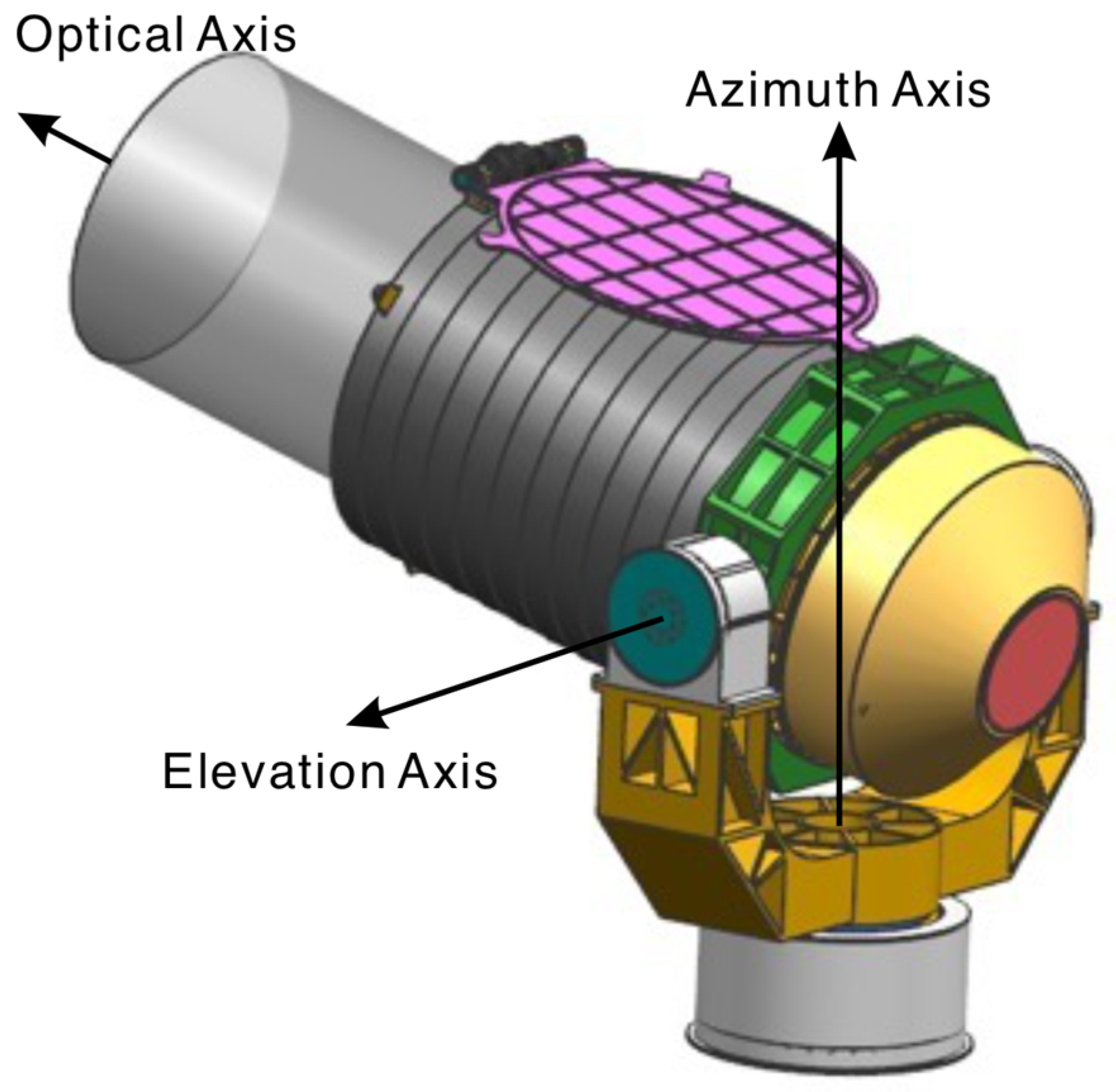
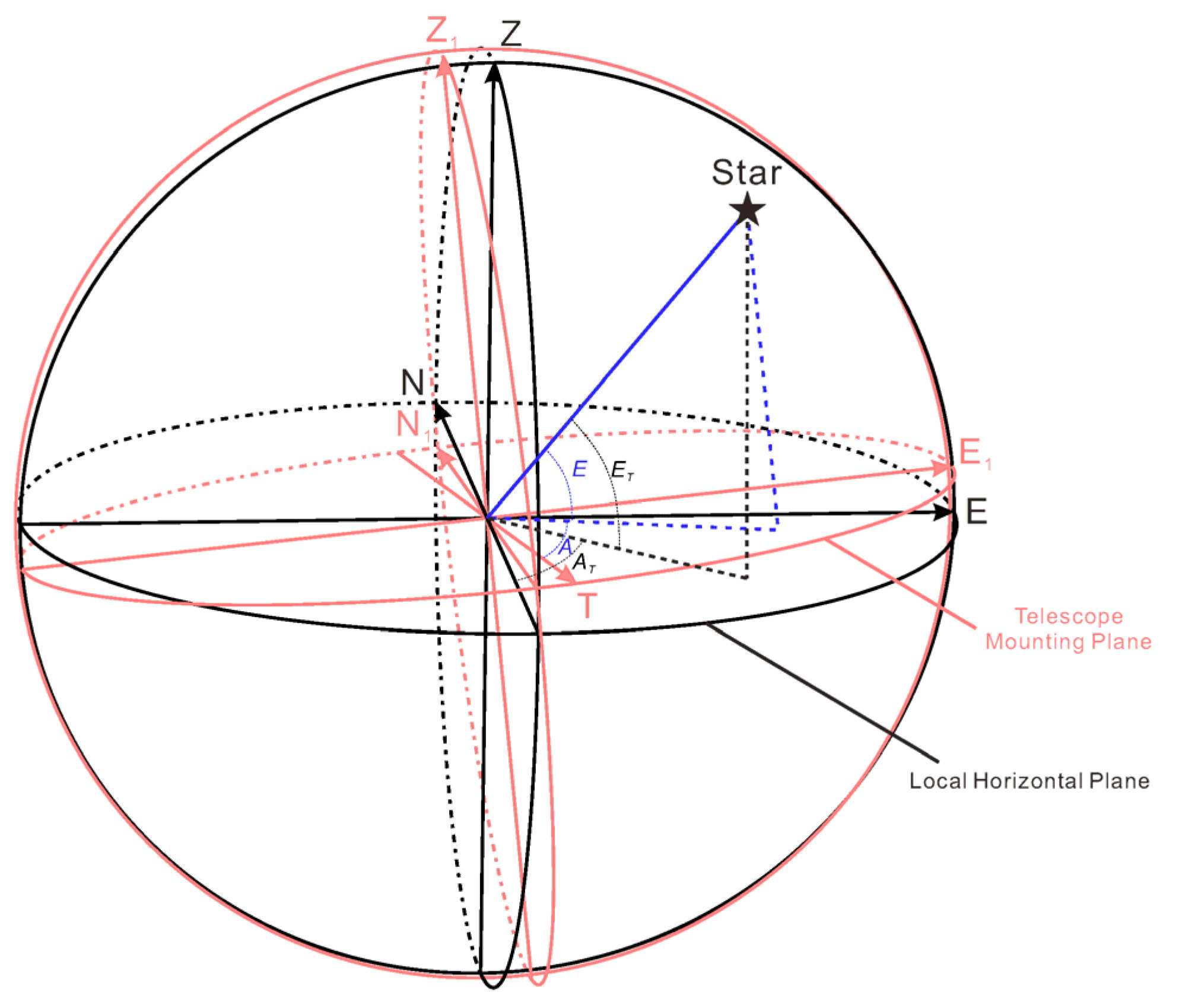
For an alt-az mounting telescope, the calibration of the pointing model is more complicated. The pointing of an alt-az telescope is realized through its azimuth axis and elevation axis. The azimuth motor drives the azimuth axis to point the telescope to different azimuth angles in the horizontal plane. The elevation motor drives the elevation axis to point the telescope to different elevation angles in a meridian plane determined by the azimuth angle. Usually, the elevation angle is defined with respect to the local horizontal plane, and the azimuth angle is defined with respect to a direction on the local horizontal plane, such as local north or local south. Therefore, the pointing errors of alt-az telescopes are mainly composed of two aspects, one is the inclination of the telescope’s mounting plane with respect to the local horizontal plane, and the other is the rotation angle of the telescope in the mounting plane relative to local north. Other minor factors include the orthogonality between the azimuth and elevation axes, the mechanical accuracy of axes that are determined by the accuracy of the encoders, and atmospheric refraction [
2]. The objective of calibrating the pointing model is to characterize these errors and correct them during telescope operation. The orthogonality and the mechanical accuracy can be well measured during laboratory tests, and atmosphere refraction can be well corrected, given the geographical location of the telescope and a reference atmosphere model. Therefore, the main task of pointing model calibration at a telescope mounting site is to determine the mounting errors.
By establishing a precise pointing model, the telescope’s observational results can be enhanced in terms of accuracy and reliability, ensuring the effective implementation of astronomical observations and research. This is of significant importance in fields such as astronomy, aerospace, and planetary sciences. Many articles have introduced the principles and methods of the telescope pointing model [
2,
3,
4,
5,
6]. Meeks et al. [
3] achieved high-precision pointing calibration for the Haystack antenna by measuring the radiation from cosmic radio sources. The pointing errors were fitted by the method of least squares to determine seven instrumental parameters that take into account the axis-alignment errors and the gravitational effects on the antenna structure. In the end, they achieved highly accurate pointing with an elevation axis error of 12.42 arcs and an azimuth axis error of 10.44 arcs. Kong et al. [
2] expanded the linear calibration model with Fourier expansion in order to establish a nonlinear calibration model for a 40-m radio telescope of alt-az mounting and achieved an overall pointing accuracy of 18.9 arcs. Huang et al. [
4] introduced a novel telescope pointing calibration model that utilized a semi-parametric regression model to compensate for the nonlinear errors in telescope pointing. Ultimately, they achieved pointing errors of 0.99 arcs in the elevation axis and 1.40 arcs in the azimuth axis. However, the original errors in the elevation axis and azimuth axis of the telescope (without any pointing model) were 39.57 arcs and 5.81 arcs, respectively. Yan et al. [
5] employed an Allan-variance-based semi-parametric model to perform pointing corrections on a 1-m diameter alt-az telescope. They achieved a pointing accuracy of 1.31 arcs in the elevation axis and 1.13 arcs in the azimuth axis, starting from the initial errors of 18.15 arcs in the elevation axis and 26.35 arcs in the azimuth axis. He et al. [
6] employed an optimized parameter model for the Moving-Platform Electro-Optical Telescope. A complex transformation matrix, with 15 dimensions, was adopted. Ultimately, they achieved a pointing accuracy with mean errors of 17.55 arcs in the elevation axis and 17.99 arcs in the azimuth axis. The above-mentioned telescope pointing calibration methods and models all adopted complex functions with multiple parameters (e.g., 14 parameters in Kong et al. [
2] and 15 parameters in Yan et al. [
5]). A simplified and accurate calibrating model that can be quickly applied to calibrate the telescope’s pointing is necessary.
The Planetary Atmospheric Spectroscopic Telescope (PAST) was an ultraviolet (UV) –visible telescope with a diameter of 0.8 m. It was constructed through the strategic priority research program of the Chinese Academy of Sciences (CAS), in collaboration with the near-space science experiment system [
7,
8,
9]. The primary scientific objectives of the telescope were to investigate the orbital motion characteristics, atmospheric and plasma distribution patterns, and spectral radiation attributes of the celestial bodies situated within the orbital path of Jupiter in our solar system. The telescope was designed for dual operation—one on a balloon-based platform and the other at a ground station. The PAST telescope was successfully installed at Saishiteng Mountain, Lenghu Town, Qinghai Province in the year 2022.
The accurate pointing and stabilization of the PAST is realized in two steps. The first is the rough pointing realized by the azimuth axis and elevation axis. The second is accurate pointing and image stabilization realized by a focusing and stabilizing mirror [
9]. The field of view of the planet sensor is limited to 2 arcminutes in order to ensure the high frequency acquisition of images. The displacement information of the target in the planet sensor is fed to the focusing and stabilizing mirror, the corresponding high frequency swing of which in two dimensions will ensure that the target is stabilized at a fix pixel. In order to achieve swift and accurate pointing towards scientific targets, the accuracy of the pointing model should be better than 1 arcminute for both the azimuth and elevation axes. Here, we implemented a novel type of telescope pointing model. This streamlined version of the pointing model was put into practice on the PAST telescope, and the results have exhibited a significant reduction in pointing errors along both the azimuth and elevation axes. This led to rapid target acquisition and an enhancement in the overall observation efficiency of the telescope. Based on these favorable outcomes, we intend to extend the application of this model to the calibration of other alt-az telescopes.
The structure of this paper is as follows: In
Section 2, we describe the principles of the pointing model, while the methodology for creating the telescope pointing model is presented in
Section 3.
Section 4 discusses the results of calibrating the PAST telescope using the pointing model. The final section provides a discussion and conclusion.
3. The Methodology for Creating the Telescope Pointing Model
The calibration method for a telescope’s pointing model based on two-dimensional surface fitting is characterized by the following steps:
3.1. Step 1: Capture Sky Images
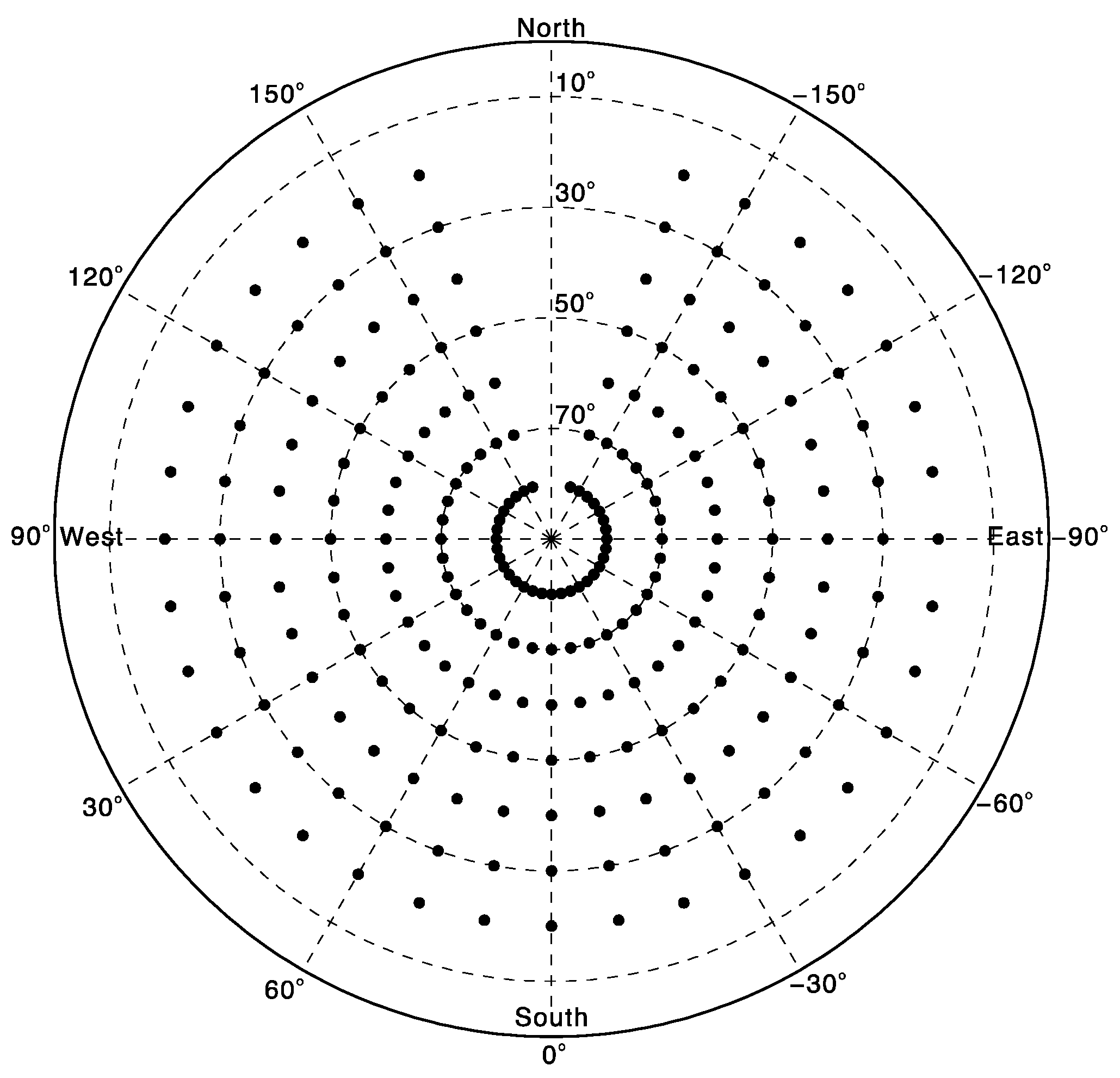
During a clear night, the sky images were captured by inputting telescope azimuth and elevation angles at intervals of 10 degrees in both azimuth and elevation directions. Due to the telescope limitations, the azimuth axis has a rotation range from −160 degrees to +160 degrees (with 0 degrees corresponding to true south), and the elevation axis has a rotation range from 20 degrees to 80 degrees for PAST. We matched the observation images with standard star charts to obtain the equatorial right ascension and declination in the J2000 epoch corresponding to the image center (i.e., the telescope’s optical axis). The sky coverage of the pointing measurements for the PAST telescope is illustrated in
Figure 3.
In this work, we used the Astrometry.net system [
10], which is widely used in astronomical and planetary communities, to calibrate the sky images. The Astrometry.net system is a reliable and robust system for calibrating astronomical images of arbitrary provenance, which we used to detect the stars in the image at a sub-pixel accuracy. For a successfully calibrated image, the right ascension and declination in the J2000 epoch for the central pixel of the image are returned. The field of view of the PAST is 15 arcminutes, with a wavelength ranging from 280 nm to 680 nm. The exposure time for the sky map in each direction is 0.2 s, which is short enough to avoid star trails, while ensuring that enough stars can be captured in the images. To ensure the reliability of the results, the number of stars in each map is more than 10.
Figure 4 shows an example of an original sky map at an elevation angle of 50 degrees and an azimuth angle of 100 degrees.
The pixel resolution of the PAST telescope is 0.5 arcs, therefore, the accuracy of the right ascension and declination of the image center is better than 0.5 arcs, which is sufficiently high enough to calibrate the pointing model. It is noted that other important error factors in this step include the deviation between the true optical axis and the central pixel of the image and the deviation between the optical axis and the mechanical axes. During the laboratory alignment of the optical system, the optical axis was precisely adjusted to the center of the image. The pointing mechanisms are composed of a high-precision encoder and a stepping motor; however, the mechanical imperfections and sensor inaccuracies could not be eliminated. During laboratory calibration, these mechanical errors were determined with an uncertainty of less than ~2 arcs using a high-precision Leica theodolite. We left these as system errors, which will be naturally corrected in the model fitting process.
3.2. Calculate Azimuth and Elevation Angles
Since the pointing of the alt-az telescope is based on the local geodetic horizontal coordinate system, the right ascension and declination of the image center should be transformed to the local geodetic horizontal coordinate system to obtain the true azimuth and true elevation angles of the telescope pointing. The calculation is realized using a standard astronomical program [
11] with input parameters of the image observation time (universal time), the telescope’s geographical latitude and longitude, the elevation of the mounting site, and the temperature and atmospheric pressure during the observation.
In the calculation process, atmospheric refraction must be corrected, especially for low elevation angles. The atmospheric refraction
R [
12] at sea level can be expressed in minutes of arc as follows:
where
E is the apparent elevation angle. The effect of refraction increases when the atmospheric pressure increases or when the temperature decreases. Therefore, a correction factor should be multiplied to
R. If the pressure at the telescope mounting site is
P millibars, and the air temperature is
T Kelvin, the factors is (
P/1010) × (283/T). Note that the above formula is only applicable for
E > 15°. Our PAST telescope also operates at
E > 15°. The final true elevation angle is obtained by subtracting
R.
By subtracting the input telescope azimuth angle from the true azimuth angle and subtracting the input telescope elevation angle from the true elevation angle, the azimuth angle error matrix and the elevation angle error matrix can be obtained, respectively. Ten sky images are captured for each pointing direction, from which ten azimuth angle errors and elevation angle errors can be derived. Then, we use the averaged values to represent the pointing errors at that direction. The uncertainties represented by the 95% confidence intervals for the azimuth axis and the elevation axis are 1.5 arcs and 1.7 arcs, respectively. These uncertainties might be derived from the wind disturbance, the mechanical imperfections, and the sensor inaccuracies, and have little influence on the pointing model.
3.3. Fitting the Pointing Model
The pointing error distribution of an alt-az telescope is typically characterized by a series of sine or cosine functions. This method utilizes a fundamental function, as follows:
where
Φ represents the true azimuth angle and
Θ represents the true elevation angle, both of which in the local geodetic horizontal coordinate system. The coefficients
A1(
Θ),
A2(
Θ),
A3(
Θ), and
A4(
Θ) are functions of the elevation angle. The fitting is realized in the following three sub-steps:
Step 1: A function fitting is performed on the azimuth angle error matrix. For a given elevation angle
Θ, a sine function fitting is performed on azimuth angle error data gathered at different azimuth angles. This process yields multiple sets of coefficients, as follows:
Here, i = 1, 2, … n, where n is a positive integer representing the number of elevation angles observed. A1i, A2i, A3i, and A4i represent the coefficients of the basic function corresponding to the elevation angle Θi. In this work, we imaged the sky at 7 elevation angles, from 20° to 80°, with a step of 10°.
Step 2: Separate function fittings on
A1i,
A2i,
A3i, and
A4i, with respect to the elevation angle
Θi (
i = 1, 2, …
n,
n = 7), are performed to derive functions
A1(
Θ),
A2(
Θ),
A3(
Θ), and
A4(
Θ). These functions can also be obtained for any arbitrary elevation angle
Θx through interpolation. As a result, the azimuth angle error function is established as follows:
For the elevation angle error matrix, the same fitting method as the azimuth angle error matrix can be applied. This allows the establishment of the elevation angle error function, as follows:
Step 3: The correction of the residual errors is performed. After we have obtained the two functions,
ΔΦ(
Θ,
Φ) and
ΔΘ(
Θ,
Φ), we can calculate the residual errors of the functions relative to the error matrices. The azimuth and elevation residual errors are then both fitted with a 5-order polynomial, as follows:
The final azimuth error functions are as follows:
and the elevation error functions are as follows:
3.4. Telescope Pointing Error Correction
In practical usage, astronomical ephemeris is initially employed to calculate the true azimuth and elevation angles of the observed target. These values are then input into the azimuth and elevation angle error functions to obtain the azimuth and elevation angle errors for that specific direction. The corresponding telescope azimuth angle, ΦT, is obtained by subtracting the azimuth angle error from the true azimuth angle, and the telescope elevation angle, ΘT, is obtained by subtracting the elevation angle error from the true elevation angle. By inputting ΦT and ΘT into the telescope control system, the accurate pointing of the telescope toward the desired target can be achieved. When a time series of ΦT and ΘT values are input into the control system of the telescope, the control system will order the telescope toward specific direction at a given time step. Currently, a time step of 0.1 s is adopted by the PAST telescope. For example, every 0.1 s the telescope control system will turn the telescope according to the position of the target at the current moment. The stabilization of the telescope is then achieved by the high-frequency-swing stabilizing mirror, and the movement of the target in the image is eliminated and the target will be fixed at a specific pixel, with uncertainty in the order of one pixel (0.5 arcs).
4. Calibration Results for PAST
By capturing stellar targets, we obtained the original absolute error map of the PAST telescope at different positions (
Figure 3) when no pointing model was applied, as shown in
Figure 5. For the PAST telescope, the azimuth angle is defined with respect to the local south, with
ΦT = 0° for the local south direction and
ΦT = 180° or −180° for local north. The azimuth angle is negative when the telescope rotates eastward, and the azimuth angle is positive when the telescope rotates westward. The elevation angle is defined with respect to the mounting plane of the telescope, with
ΘT = 0° for horizon and
ΘT = 90° for zenith. From
Figure 5, it can be observed that the overall absolute error in the azimuth axis of the PAST telescope is relatively large and irregular, while the absolute elevation axis error is smaller and more regular. The distributions of the errors at each elevation angle are similar to a sine function. Such distribution characteristics give us the inspiration to use trigonometric functions to fit the pointing model. Additionally, we have also generated a fitted three-dimensional error map of the PAST telescope, as depicted in
Figure 6.
Figure 7 displays the final residual error distributions of the azimuth and elevation axes of the PAST telescope after applying this pointing model. Comparing it to
Figure 5, it is evident that the pointing accuracy of the PAST telescope has significantly improved. For both the azimuth and the elevation axes, the majority of the residual errors are within 10 arcs. After calibration, the root mean square errors (RMSE) of the azimuth axis and elevation axis of the PAST telescope are 6.8 arcs and 3.8 arcs, respectively. Compared with previous models, our simple model achieved a high accuracy. The previous calibration methods and models have achieved a high pointing accuracy of less than 2 arcs but based initial pointing errors of less than 1 arcminute [
4,
5]. The advantages of the novel method proposed in this paper are that there are no limitations on the initial pointing errors and that no prior knowledge of the properties of the initial pointing errors is needed. The field of view of the planet sensor is 2 arcminutes, and the pointing precision of the model is high enough to ensure that the target appears in the planet sensor, based on which the stabilizing mirror can stabilize the target to a fixed pixel, with an accuracy of 0.5 arcs.
5. Conclusions
In order to enhance the pointing accuracy of the PAST telescope, we have developed a new simplified version of the telescope pointing correction model. This greatly streamlines the previously complex telescope pointing model fitting equations, allowing us to quickly obtain a high-precision telescope pointing model. With this method, the pointing accuracy of the PAST telescope is better than 10 arcs, with an RMSE of 6.8 arcs for the azimuth axis and that of 3.8 arcs for the elevation axis.
The primary influencing factors of the pointing error in the alt-az telescope include the levelness of the installation plane, whether the azimuth axis is accurately aligned with true south or north, and the vertical alignment between the azimuth and altitude axes. Therefore, to achieve a rapid and accurate pointing of the observation targets and improve observation efficiency, a pointing model for correction is required. All alt-az telescopes have the same mounting on a concrete pier; therefore, the simple model that has been proposed in this paper can be widely applied to other alt-az telescopes. In the next steps, we will extend this simplified pointing model calibration method to other alt-az telescopes at the Lenghu site and verify its reliability, stability, and generalizability. In addition, it has been proposed that, apart from the telescopes’ inherent system errors, which are generally small, the telescope pointing model could be represented by two angles, one of which is the tilt angle between the mounting plane of the telescope, and the other is the rotation angle of the telescope in the mounting plane. In future work, we hope to try another, simpler model, that is, using the observed pointing data to calculate the above-mentioned two angles in order to establish the pointing model.


 ,
, 