Abstract
Different methodologies for manipulators have been proposed and applied to robot obstacle detection and avoidance in unstructured environments. These methods include different real-time sensors, observer-based algorithms, and path planning using genetic algorithms. However, sensor design integration is complex and considerably expensive. Moreover, the observer algorithm requires complete system dynamics information, which is difficult to derive. In this regard, genetic algorithms are typically considered slow and difficult to optimize. Accordingly, this study proposes a sensor-less obstacle detection technique using a nonlinear observer (known as sliding perturbation observer (SPO)). Obstacle avoidance is also implemented using a motion planner (known as artificial potential field (APF)). The SPO is a nonlinear observer that only requires the partial position and provides all other states (such as position, velocity) and perturbation (non-linearities and external disturbance). The SPO estimates the external torque at each joint resulting from contact (i.e., collision) with an obstacle. Obstacles are detected and avoided by integrating the SPO and APF. The estimated external torque detects the obstacle location and a repulsive force from the APF is applied to avoid this obstacle. To achieve obstacle avoidance, the sum of all estimated torques must be zero. The proposed technique is applied to a robot manipulator with five degrees of freedom.
1. Introduction
Robots currently play a vital role in industries by boosting productivity rates. These machines not only support workers in performing tedious tasks, but also saves a considerable amount of time in accomplishing these tasks. In some areas, robots have replaced all workers and only robot supervision is required. With technological advancements over the last decade in this evolving world, safety concerns in the industrial environment have become a critical factor. Inventors, scientists, and researchers are expected to implement protective measures in the workspace for people, the environment, and hardware based on their studies and findings. Because robots have begun to be involved more regularly in business activities, safety challenges must be addressed. In the case of a robot manipulator, obstacle collision detection and avoidance are critical elements for clean and secure task completion. Several techniques for collision detection and avoidance have been formulated by many researchers. For example, a mechanism that minimizes the harm resulting from collisions may be introduced [1,2] and a vision sensor can be employed to avoid obstacle collision [3]. Low-cost ultrasonic sensors are used for obstacle detection and avoidance [4]. Skin sensors have also been introduced for collision detection [5]. Research was carried out on joint torque sensors placed in robots for obstacle detection [6]. The abovementioned methods were effective but had some drawbacks. For instance, introduction of additional hardware reduces efficiency and flexibility as well as increasing robot complexity. In some industries (such as the nuclear powerplant dismantling industry), where the working environment is harsh and complex, the sensor-based solution is not an acceptable choice. The current study is conducted on a remote-controlled robot manipulator in an environment fully exposed to nuclear radioactive rays. Such an environment can reduce the accuracy of a sensor. Some heavy-duty sensors are also available for such environments; however, they are costly and exhibit certain design problems. The most important aspect considered in collision detection is the measurement of contact force. One solution for determining this force is to use force or torque sensors. However, these sensors are difficult to use in medium- or high-level radiation due to structural and cost problems. Therefore, a force estimation method is needed, which can estimate the contact force or detect collision to ensure the safety of the environment and hardware in the unstructured environment. Collision detection in an unstructured environment is a very critical task to consider where the robot is blind or does not have any information about the obstacle. Observers are widely used for the control of nonlinear systems [7,8,9,10]. Many researchers have come up with the idea of using dynamics-based observers instead of sensors. The residual observer technique is used for collision detection purposes [7]. Some researchers also used dynamics-based observers to detect collisions by observing the external torque [11]. However, these methods are either based on exact dynamics assumptions or have some known information about the obstacle such as the size and number of obstacles.
At the moment of collision in an unstructured environment, the most important factor to consider is the contact force/reaction force that the manipulator experiences at each joint. Since sensors cannot be used in current study, the estimation of contact force becomes critical. Early approaches to estimating contact force were introduced in [12] and implemented in a robot arm [13]. P. Hacksel et al. proposed an external force observer based on manipulator dynamics and only the position feedback to estimate the external force [12]. However, the disadvantage of this approach is that it is necessary to know the precise position information, and accurate dynamics equation of the robotic manipulator [14,15] shows the estimation of each joint’s external torque using motor current, but the drawback is that friction is very hard to estimate using this method.
After resolving the problems relevant to obstacle collision detection and contact force estimation, the next critical step is obstacle avoidance. Various solutions have been devised by several researchers to resolve this problem. Authors of [16,17] used the V-graph algorithm for searching the shortest path without having contact with the obstacle in the robot manipulator workspace. The genetic algorithm method was introduced to avoid the obstacles in [18,19,20]. However, this method is extremely slow and difficult to optimize. Considering the nature of the nuclear environment, we need a method whose computation speed is fast and easy to debug. These abovementioned methods have shown their effectiveness, but a single approach is not always the best manner to resolve the issues, as they all show numerous weaknesses.
In summary, collision detection methods are generally expensive. Moreover, they are sensor-based; consequently, the overall cost of the robot increases. Other methods have certain limitations, owing to the assumptions of an exact dynamic model. The end effector contact force is also one of the critical aspects of the unstructured environment to be considered. Similarly, the method should also account for obstacle avoidance. Therefore, there is a need for a technique that can accurately detect an obstacle collision in the unstructured environment and avoid that obstacle.
The purpose of this research is to design a technique for sensor-less collision detection and its avoidance in the unstructured environment, without altering the hardware that can be applied to existing systems. To achieve this purpose, this paper proposes the integration (Olgac et al.) of the sliding perturbation observer (SPO) and artificial potential field (APF) algorithm to detect and avoid obstacles [21]. The effectiveness of the algorithm is verified through continuous obstacle avoidance in a simulator. The simulations and results show that obstacle detection and avoidance are relatively accurate at low speeds. The main contributions of this study is presented as follows:
- The nonlinear term of gravity is calculated for the system with five degrees of freedom (DOFs) and verified using the Simscape Multibody gravity robotics toolbox.
- The proposed method for detecting contact/collision uses the SPO and calculates gravity model by saving the end effector position as an obstacle location.
- The APF is integrated with the desired velocity trajectory to avoid obstacles. With this integration, the robot can move at a desired velocity (except during obstacle avoidance) from the initial to the final position.
- A relationship for selecting the gradient descent rate based on the threshold radius is established to avoid collision and improve performance.
As a result of these efforts, the manipulator can detect obstacles and avoid collision in the unstructured environment, without the use of heavy-duty sensors. The SPO uses linear dynamics unlike the other residual observers (which use exact dynamic model assumption) to estimate the perturbation (nonlinearities and external disturbance) at each joint. External torque is estimated using SPO and gravity, which determine whether the collision occurs or not. The robot is programmed with a polynomial trajectory from the initial position to the goal position in cartesian space. The repulsive force from the artificial potential field is applied in a cartesian space to avoid obstacle collision. This motion planner method is easy to implement, unlike trajectory planning, using genetic algorithms. All the simulations are performed in MATLAB, Simulink, Simscape Multibody toolboxes.
The remainder of this paper is organized as follows: Section 2 describes the system, its controls and the dynamic model of the system. Section 3 presents the main algorithms for collision detection, contact force estimation and obstacle avoidance. Section 4 discusses the simulations and results have been discussed. Section 5 summarizes the conclusion of this study.
2. System Description, Dynamic Model, and Controls
2.1. System Description
A nuclear plant is shown in Figure 1. The main purpose of the system is to cut the reactor vessel internals (RVI) remotely using a three dimensional (3D) haptic device. The six DOF robot manipulator has five revolute joints and one prismatic joint. The proposed technique is carried out on five DOF robots (revolute joints) while cutting inside RVI. The obstacle can be the wall of the RVI or any cutting material on its way. The five DOF robot manipulators go into the round shape reactor vessel internally (RVI) for cutting purposes. The computer-aided design (CAD) of the robot can be seen in Figure 2 [22].
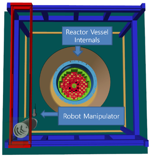
Figure 1.
Nuclear powerplant simulator.
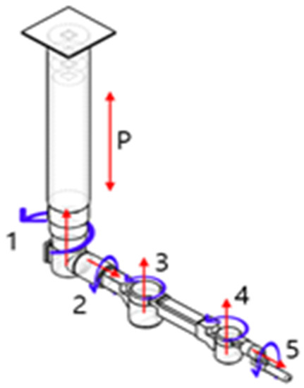
Figure 2.
CAD robot manipulator [23,24].
In the nuclear powerplant simulator (Figure 1), the RVI wall is shown as a nonsolid surface. Hence, when the robot hits the RVI wall, it passes that wall because of the nonrigid surface. To make solid contact with the RVI, we used the Simscape contact force library called sphere-to-tube. The sphere attaches to the end effector of the robot manipulator and the tube covers the RVI Shape. The toolbox is shown in Figure 3.
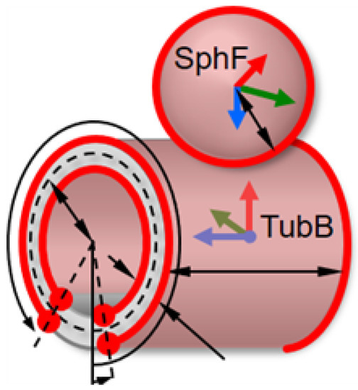
Figure 3.
Sphere-to-Tube dimension.
The reason for transforming the contact with the RVI wall into solid contact is that the robot can experience impact if it hits the wall. The toolbox also provides the magnitude of contact reaction force.
2.2. Dynamic Model
Consider the following equation for system dynamics:
where , , , and denotes the control torque, inertia matrix, Coriolis and centrifugal force, and gravity acting on each joint, respectively. In real systems, unknown nonlinear terms are the forms of , , and disturbance [23].
2.3. Controller
The controller used in this study is an integral sliding mode controller (ISMC). The reason for choosing this position controller is that it does not require a mathematical model of the system. The ISMC control input applies a switching gain to compensate for the perturbation and system dynamics [25]. The control input of the ISMC can be expressed as
where is a constant, s is a sliding surface, is the switching gain, is the control input, and σ is the actual sliding variable. The sat function is used to minimize the chattering in the system. is the boundary layer thickness. In the ISMC, the controller output does not require dynamic information because only the output feedback of the plant is required.
3. SPO-Based Collision Detection and Obstacle Avoidance Using APF
This section presents the formulation for disturbance observer, force estimation and motion planner for obstacle avoidance.
3.1. Estimation of External Torque Using SPO
3.1.1. SPO
The SPO is a nonlinear observer that only needs partial information (position) and yields all other states such as position, velocity, and perturbation . The perturbation is used to estimate all nonlinearities and disturbances in the system’s dynamics. The general form of SPO can be expressed as [21,26]:
where is the estimated perturbation at each joint; and are the estimated states (positions and velocity, respectively); hat (∧) and tilde (~) symbols represent the estimation and error states, respectively. The saturation function is denoted as. is the new state variable for estimating the perturbation. , , , , are constant values and can be obtained from , , . is the compensated control input and is the control input from the controller. is a positive constant used to tune the parameter for better performance and for stable pole placement [25] and is the compensated control input from the SPO.
3.1.2. Gravity
In the real world, calculating an accurate dynamic model of the system is problematic. Nonlinearities, unmodelled dynamics, and external disturbances play their roles (gravity, Coriolis, and inertia) in calculating dynamics. The gravity term equations are calculated graphically for our system and are estimated with Simscape gravity torque block (robotics toolbox) [24]. The calculated result has totally comparable conduct with toolbox one when a certain trajectory is provided at joint 2, as shown in Figure 4. The angle represents the i-th joint angle and represents a length the of i-th link of the robot manipulator. The gravity equation is calculated as follows:
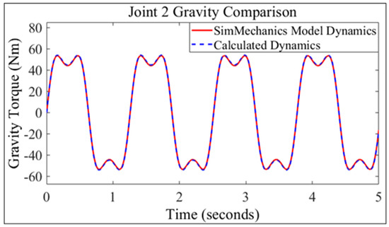
Figure 4.
Comparison of dynamics [26].
3.1.3. Estimation of External Disturbance Torque due to Collision
Consider the following equation of SPO:
where is the external torque at each joint owing to collision (disturbance). , , and are the gravity, nonlinear, and unmodelled inertia and Coriolis force terms. The main task of this research is to detect a collision inside the RVI. Inside the RVI, the speed of the robot is slow. The allowed speed in the RVI is 0.025 to 0.05 m/s. Thus, we can neglect the Coriolis and inertia term because in the current scenario, gravity plays main role in the nonlinearity of the system The equation reduces to the following:
Assuming inertia and Coriolis are negligible due to low speed in the RVI. To verify the above assumptions, we took a desired speed of 0.05 m/s and ran the simulations for about 300 s and provided a simple trajectory to the robot so that perturbation and gravity of the system could be observed.
As shown in Figure 5, at low speeds, the perturbation is virtually equal to the calculated gravity. Based on Equation (13), if collision does not occur, then the external estimated joint torque is zero.
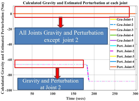
Figure 5.
Comparison between calculated gravity and SPO.
3.2. Estimation of Force Using External Disturbance Torque
To detect collision, the reaction force must be considered. When the robot end-effector collides with the surface of the RVI, then reaction force is generated by the wall as shown in Figure 6. In this research, only the end effector reaction force is estimated. This force can be used in further studies for impedance control (for hardware safety). This is because if the reaction force is excessively high at the moment of collision, then it can damage the hardware as well as the surrounding environment. The following formula is used to estimate the end effector force [27,28]:
where is the Jacobian matrix of order 3 × 5 and is the transposition of the Jacobian. indicates the pseudoinverse Jacobian and is the estimated external torque calculated by the (SPO).
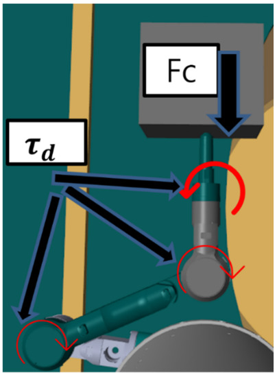
Figure 6.
Contact force impact on joints.
3.3. Obstacle Avoidance Using APF
The APF is a collision avoidance method that uses calculations of the repulsive (or attractive) forces between obstacles and the body of the manipulator. The force between body and obstacles is defined as a function of their distance [29]. Equations (16) and (17) define an attractive potential according to a distance between a current position of the robot and goal .
where .
is the “attractive” potential; ζ = attractive constant.
In Equation (16), when the attractive potential is less than or equal to a set threshold R, the quadratic potential of the distance is applied to slowly reach the goal. When the distance is greater than the R, a conical attractive potential is applied to approach the goal quickly. The gradient of this potential is the attractive force =(q), which is calculated in Equation (17). Similarly, Equation (18) shows that the repulsive potential is applied when the distance between a robot’s current position and an obstacle position is less than or equal to a set threshold R, otherwise it is zero. The gradient of this repulsive potential, which is the repulsive force = −(q), is calculated as follows:
where .
where R is the distance threshold and is a repulsive constant. In Equations (18) and (19), the distance between the robot end-effector and obstacle is very important for calculating the repulsive force. The two-dimensional distance is considered in the RVI because the robot is assumed as moving in x and y directions only. The distance between them is calculated using the following formula. The same method is followed to calculate the distance from the goal position.
where , are the coordinates of the robot current end-effector positions from the desired Cartesian trajectory and , are detected obstacle position using the estimated external torque while performing cutting/scanning in the RVI. Figure 7 provides a better idea for understanding the artificial potential field. Total potential force is defined as
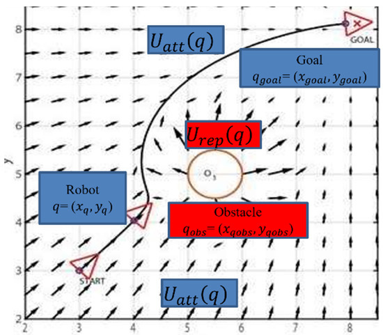
Figure 7.
Attractive and repulsive potential field [30].
In this study, the attractive potential of an artificial potential field is replaced by Cartesian space trajectory. The polynomial trajectory from the initial position to goal is planned in Cartesian space. Cartesian space trajectories relate to the motions of a robot relative to the Cartesian reference frame. In Cartesian space, the joint values must be repeatedly calculated through the inverse kinematic equations of the robot. The path parametrization between two starting and goal points is defined as [31]:
where and are the initial and final known positions, respectively. Moreover, s = σ/L, and σ [0, L] is the arc length (which yields the current length of the path). L is defined as ||||. The following equation shows the timing law in Cartesian space trajectory:
where and are known, and . The following Figure 8 graphically represents the equation.
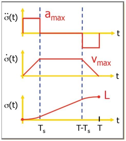
Figure 8.
Timing law in Cartesian space trajectory.
To prevent the robot manipulator from being obstructed, the repulsive force from the potential field is used. When the robot reaches the threshold area, then the trajectory tracking equation for system is as follows
where is the gradient descent rate, which determines the minima of the function. After a series of simulations is performed using the foregoing equation, the following relationship between the threshold radius and gradient descent is derived. The following equation indicates that that the movement of the robot can be fast if its distance is considerable.
Figure 9 shows the complete methodology used in this study. First, the desired end-effector position is determined from the 3D haptic device, then the desired trajectory of the robot end-effector is generated. The robot follows the trajectory using the inverse kinematics of the system. It operates with the unstructured environment in which we do not have any information about the obstacle. When the robot collides with an obstacle the contact force has an impact on each joint of the robot manipulator in the form of external torque, which is estimated by the SPO. The end-effector reaction force is also estimated using estimated external torque. After obstacle detection, an APF is applied to avoid the obstacle.
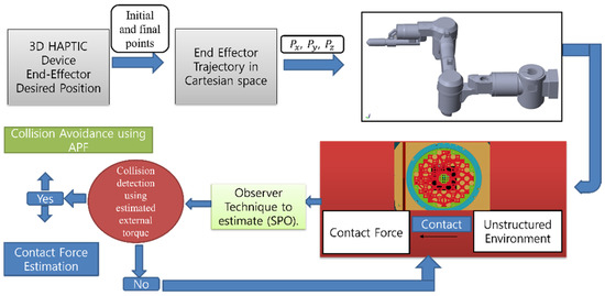
Figure 9.
Methodology.
4. Simulations and Results
4.1. Estimation of External Torque Using SPO
All the simulations are performed in MATLAB, Simulink, and Simscape Multibody toolbox. To implement the collision detection algorithm, Equation (12) is used to estimate the external disturbance torque at each joint of the robot manipulator. When collision does not occur, the sum of the estimated external torque at all joints is zero. The sum of these torques at all joints considering different speeds can be seen in the no-collision case in Figure 10.
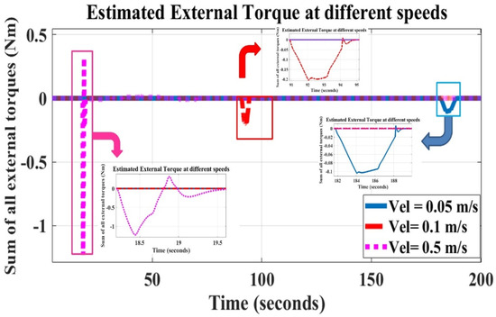
Figure 10.
Estimated external torque at different speeds with no collision.
In Figure 10, deflection from zero can be observed at different speeds and periods. Deflection occurs because the base of the robot manipulator is at the center of the RVI. To perform cutting, the end-effector must be close to the wall of the RVI. The trajectory of the end-effector causes slight deflection. The solution to this deflection is to set the threshold value at different speeds. If the external estimated torque exceeds the set threshold, then collision has occurred. The deflection increases with the increase in speed because the inertia and Coriolis force terms have been neglected. Nevertheless, deflection has a negligible impact at low speeds, as discussed in previous section. In Figure 11, when the robot end effector collides with the obstacle (RVI wall) twice, the estimated external torque exhibits two spikes. Note that the obstacle is a wall and is considered a continuous obstacle.

Figure 11.
Estimated external torque when collision takes place.
Next, the collision detection is considered as the end effector reaction force. At the time of collision with the obstacle, the robot scans the obstacle and records its position. Equation (15) is used at that moment to estimate the contact force for verification purposes. The estimated force is also compared with the contact force library in the Simulink. Both results were compared and found to be the same, which validates the contact estimation algorithm. The Figure 12 shows the results of the estimated and toolbox force.
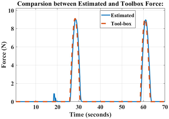
Figure 12.
Estimated force vs. force provided by toolbox.
4.2. Obstacle Avoidance Using APF
After detecting the obstacle using the SPO and estimating the end-effector contact force, the next and final step is to avoid the obstacle. At the time of collision, the proposed technique saves the robot end-effector position. The method used for collision in the current study is APF. It generates a repulsive potential when it comes near (threshold value) to the obstacle. The two different scenarios are presented, but for good understanding, let us define the desired end-effector trajectory first. The following Figure 13 and Figure 14 show the desired end-effector trajectory for the five DOF robot manipulator in x and y directions. In the RVI, the robot only moves in the x and y direction. Currently, we only consider the collision possibilities in the RVI. The collision can be either with the wall of the RVI or any material that manipulator is cutting.
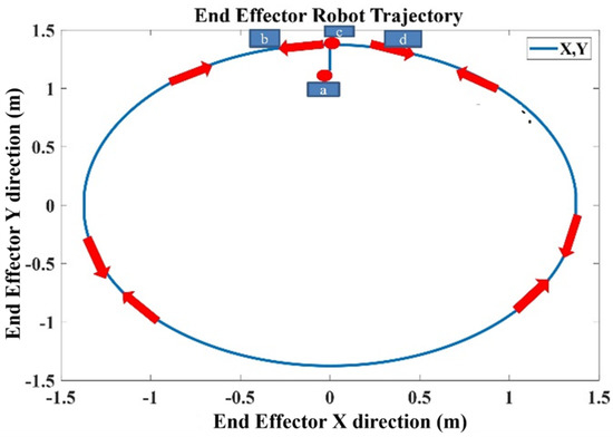
Figure 13.
Robot end-effector trajectory. (a) The robot end effector’s starting position; (b) going left and toward the wall of RVI; (c) completing the scanning of RVI; (d) after completing scanning of the RVI, it reverses direction and reaches its final position.
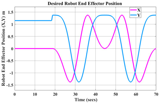
Figure 14.
Robot end effector trajectory with time axis.
First, consider the obstacle at point (−0.986, 0.9452). In this instance, the obstacle location is known, and APF is applied to avoid the point obstacle. Below, in Figure 15, the repulsive force avoids the obstacle based on the predefined obstacle position in the RVI.
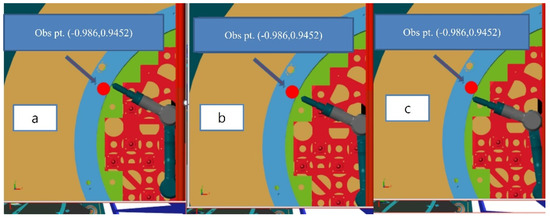
Figure 15.
Point obstacle avoidance scenario (a) before collision avoidance; (b) avoiding collision; (c) following desired trajectory after collision avoidance.
Figure 16 shows the outcome based on the robot end-effector position. When the robot approaches the obstacle (threshold = 0.04 m), the repulsive force starts acting on the robot end-effector and keeps it away from the obstacle. The reason is that it has turned a corner sharply in avoidance because the threshold radius is very small, which leads to high repulsive force. To counter it, the repulsive force is restricted to a constant value. Table 1. shows the simulation parameters used to demonstrate the results.
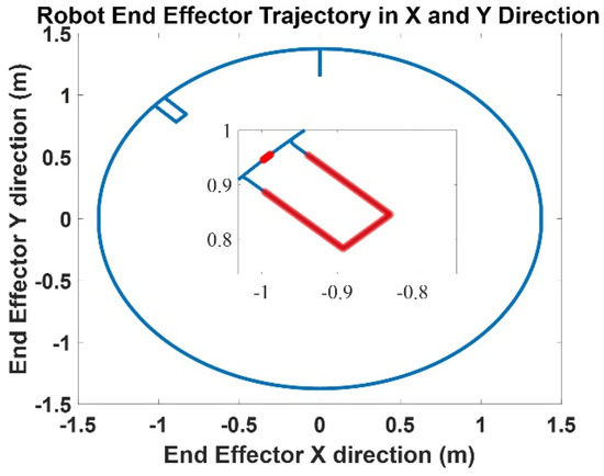
Figure 16.
Point obstacle avoidance scenario.

Table 1.
Simulation parameters.
Similarly, another scenario is of a solid obstacle of arbitrary shape in the RVI. The obstacle has a sharp-turn corner. The proposed technique first detects the obstacle during scanning and saves its location. The robot avoids it the next time it passes from the same location. The whole process can be seen in Figure 17. The end-effector trajectory can be seen in Figure 18.
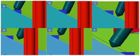
Figure 17.
Solid obstacle avoidance in simulator (end-effector). (a–c) Collision detection (scanning). (d–f) Collision avoidance after scanning and saving obstacle position (on return).
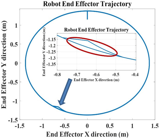
Figure 18.
Sharp-turn corner obstacle avoidance trajectory (end-effector).
Third, the RVI wall is considered a continuous obstacle. The information regarding the obstacle is unknown. Therefore, according to proposed technique, the robot first detects and scans the obstacle position and records it, using the proposed estimated external disturbance torque. When the robot passes the same position, a repulsive force acts to change the trajectory and avoid collision. In Figure 19, the first figure shows the result when only the collision detection algorithm is implemented so it detects and scans the obstacle at time 25.86 s to 31.3 s and again detects the obstacle when it comes to the same position at time 59.5 s to 64.9 s. The second figure shows the outcome when collision detection and avoidance algorithms are implemented at the same time. First the collision detection algorithm detects and scans the obstacle (25.86 s to 31.3 s) from the estimated external disturbance torque and then, using the artificial potential field, obstacle collision is avoided. This is why the estimated external torque is zero from time 59.5 s to 64.9 s, which is a good sign for our system.
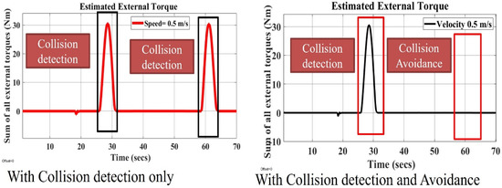
Figure 19.
Continuous obstacle detection and avoidance scenario.
Figure 20 shows the results of avoiding the obstacle using the artificial potential field on the nuclear power plant virtual simulator. Figure 21 shows the robot end effector trajectory in circular shape inside RVI. When the robot is near to this continuous obstacle, or when robot is 0.04 m away from the obstacle, repulsive force is generated to keep the robot away from that obstacle. The avoidance trajectory can be seen in Figure 18, which is not very smooth due to nonoptimized parameter selection ( and ) of the potential field parameter. Figure 21 shows the different trajectories offered by the artificial potential field to avoid a detected obstacle.
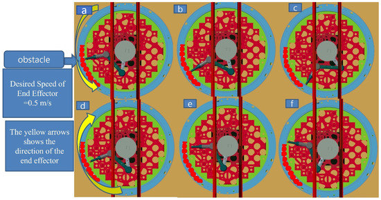
Figure 20.
Continuous obstacle avoidance in simulator (end-effector); (a–c) collision detection (scanning); (d–f) collision avoidance after scanning and saving obstacle position (on return).
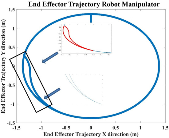
Figure 21.
Continuous obstacle avoidance trajectory (end-effector).
Figure 22 shows the desired robot end-effector trajectory with respect to the time axis, before and after collision avoidance.
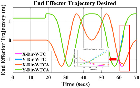
Figure 22.
Continuous obstacle avoidance trajectory versus time. WTC = without collision avoidance. WTCA = with collision avoidance.
5. Conclusions
This study aimed to estimate the external disturbance torque to detect obstacle collisions in an unstructured environment without the use of additional expensive sensors. The technique used the nonlinear observer SPO and gravity model to estimate the external disturbance torque. Collision occurred if the sum of all external disturbance torques exceeded the set threshold. This technique was evaluated at different speeds. With increasing speed, the error in the estimation increased because the nonlinear inertia and Coriolis force terms were ignored. The end-effector contact force was also estimated based on the estimated external torque and verified using the contact force in the Simulink toolbox. An APF integrated with a desired Cartesian trajectory was employed to avoid the obstacle. A repulsive force was applied to the Cartesian trajectory space when the robot approached the recorded obstacle position. During obstacle avoidance, the contact force and estimated external torque became zero, validating the avoidance. The relationship between the threshold radius and gradient descent was formulated by performing several simulations. The proposed technique can also be applied to existing systems. In the APF, parameter selection (such as the threshold radius and gradient descent rate) plays a key role in smooth collision avoidance. In the future, an optimized parameter selection using APF will be investigated to improve collision avoidance. The implementation of hardware in the proposed technique is also suggested for future work.
Author Contributions
Conceptualization, M.S.; methodology, M.S. and H.K.; writing—original-draft preparation, M.S.; writing—review and editing, M.S., H.K. and M.C.L.; supervision, M.C.L. and H.K. All authors have read and agreed to the published version of the manuscript.
Funding
This research was funded by the Nuclear Research and Development Program through the National Research Foundation of Korea (NRF) funded by the Ministry of Science and ICT (MSIT, Korea) (NRF-2019M2C9A1057807) and was funded by Korea Institute of Machinery and Materials, (Project number: NK238A, 2022, Korea).
Institutional Review Board Statement
Not applicable.
Informed Consent Statement
Not applicable.
Data Availability Statement
All relevant data are within the text.
Conflicts of Interest
The authors declare no conflict of interest.
References
- Park, J.-J.; Kim, H.-S.; Song, J.-B. Safe robot arm with safe joint mechanism using nonlinear spring system for collision safety. In Proceedings of the IEEE International Conference on Robotics and Automation, Kobe, Japan, 12–17 May 2009. [Google Scholar]
- Choi, D.-E.; Lee, W.; Hong, S.H.; Kang, S.-C.; Lee, H.; Cho, C.-H. Design of safe joint with variable threshold torque. Int. J. Precis. Eng. Manuf. 2014, 15, 2507–2512. [Google Scholar] [CrossRef]
- Mohammed, A.; Schmidt, B.; Wang, L. Active collision avoidance for human–robot collaboration driven by vision sensors. Int. J. Comput. Integr. Manuf. 2016, 30, 970–980. [Google Scholar] [CrossRef]
- Gageik, N.; Benz, P.; Montenegro, S. Obstacle Detection and Collision Avoidance for a UAV with Complementary Low-Cost Sensors. IEEE Access 2015, 3, 599–609. [Google Scholar] [CrossRef]
- Ulmen, J.; Cutkosky, M. A robust low-cost and low-noise artificial skin for human-friendly robots. In Proceedings of the IEEE International Conference on Robotics and Automation, Anchorage, AK, USA, 3–8 May 2010. [Google Scholar]
- Lou, Y.; Wei, J.; Song, S. Design and Optimization of a Joint Torque Sensor for Robot Collision Detection. IEEE Sens. J. 2019, 19, 6618–6627. [Google Scholar] [CrossRef]
- Cho, C.-N.; Kim, J.-H.; Lee, S.-D.; Song, J.-B. Collision detection and reaction on 7 DOF service robot arm using residual observer. J. Mech. Sci. Technol. 2012, 26, 1197–1203. [Google Scholar] [CrossRef]
- Chang, Y.; Zhou, P.; Niu, B.; Wang, H.; Xu, N.; Alassafi, M.O.; Ahmad, A.M. Switched-observer-based adaptive output-feedback control design with unknown gain for pure-feedback switched nonlinear systems via average dwell time. Int. J. Syst. Sci. 2021, 52, 1731–1745. [Google Scholar] [CrossRef]
- Zhang, H.; Zhao, X.; Zhang, L.; Niu, B.; Zong, G.; Xu, N. Observer-based adaptive fuzzy hierarchical sliding mode control of uncertain under-actuated switched nonlinear systems with input quantization. Int. J. Robust Nonlinear Control 2022, 32, 8163–8185. [Google Scholar] [CrossRef]
- Cao, Z.; Zhang, L.; Niu, B.; Zong, G.; Zhao, X. Observer-based adaptive output-constrained control design of switched stochastic nonlinear systems with input saturation. Asian J. Control 2022, 375, 1–14. [Google Scholar] [CrossRef]
- Lee, S.-D. Sensorless collision detection for safe human-robot collaboration. In Proceedings of the IEEE/RSJ International Conference on Intelligent Robots and Systems (IROS), Hamburg, Germany, 28 September–3 October 2015. [Google Scholar]
- Hacksel, P.; Salcudean, S. Estimation of environment forces and rigid-body velocities using observers. In Proceedings of the IEEE International Conference on Robotics and Automation, San Diego, CA, USA, 8–13 May 1994. [Google Scholar]
- Alcocer, A.; Robertsson, A.; Valera, A.; Johansson, R. Force estimation and control in robot manipulators. IFAC Proc. Vol. 2003, 36, 55–60. [Google Scholar] [CrossRef]
- Eom, K.S.; Suh, I.H.; Chung, W.K.; Oh, S.-R. Disturbance observer based force control of robot manipulator without force sensor. In Proceedings of the IEEE International Conference on Robotics and Automation, Leuven, Belgium, 16–20 May 1998. [Google Scholar]
- Park, Y.-Y.; Lee, M. Design of Compliance Controller for Robot Manipulator Using the Current Sensor. In Proceedings of the 8th Asia-Pacific Conference on Control & Measurement (APCCM), Harbin, China, 20 July 2008. [Google Scholar]
- Lozano-Pérez, T.; Wesley, M.A.; IBM Thomas, J. Watson Research Center. An algorithm for planning collision-free paths among polyhedral obstacles. Commun. ACM 1979, 22, 560–570. [Google Scholar] [CrossRef]
- Lozano-Perez, T. Automatic Planning of Manipulator Transfer Movements. IEEE Trans. Syst. Man Cybern. 1981, 11, 681–698. [Google Scholar] [CrossRef]
- Baba, N.; Kubota, N. Path planning and collision avoidance of a robot manipulator using genetic algorithm. J. Robot. Soc. Jpn. 1993, 11, 299–302. [Google Scholar] [CrossRef]
- Ahmed, A.A.; Abdalla, T.Y.; Abed, A. Path Planning of Mobile Robot by using Modified Optimized Potential Field Method. Int. J. Comput. Appl. 2015, 113, 6–10. [Google Scholar] [CrossRef]
- Baba, N.; Kubota, N. Collision avoidance planning of a robot manipulator by using genetic algorithm. A consideration for the problem in which moving obstacles and/or several robots are included in the workspace. In Proceedings of the First IEEE Conference on Evolutionary Computation, IEEE World Congress on Computational Intelligence, Orlando, FL, USA, 27–29 June 1994. [Google Scholar]
- Moura, J.T.; Elmali, H.; Olgac, N. Sliding Mode Control with Sliding Perturbation Observer. J. Dyn. Syst. Meas. Control 1997, 119, 657–665. [Google Scholar] [CrossRef]
- Khan, H.; Abbasi, S.J.; Lee, M.C. DPSO and Inverse Jacobian-Based Real-Time Inverse Kinematics With Trajectory Tracking Using Integral SMC for Teleoperation. IEEE Access 2020, 8, 159622–159638. [Google Scholar] [CrossRef]
- Salman, M.; Khan, H.; Abbasi, S.J.; Lee, M.C. Dynamics Analysis and Control of 5 DOF Robot Manipulator. In Proceedings of the 21st International Conference on Control, Automation and Systems (ICCAS), Jeju, Republic of Korea, 12–15 October 2021. [Google Scholar]
- Salman, M.; Khan, H.; Abbasi, S.J.; Kim, J.H.; Lee, J.W.; Lee, M.C. Sensor-less Obstacle Collision Detection for Robot Manipulator. In Proceedings of the 19th International Conference on Ubiquitous Robots (UR), Jeju, Republic of Korea, 4–6 July 2022. [Google Scholar]
- Abbasi, S.J.; Khan, H.; Lee, M.C. Trajectory Tracking Control of Multi-DOF Robot without Considering System Dynamics. Int. J. Control Autom. Syst. 2021, 19, 1–12. [Google Scholar] [CrossRef]
- Abbasi, S.J.; Kallu, K.D.; Lee, M.C. Efficient Control of a Non-Linear System Using a Modified Sliding Mode Control. Appl. Sci. 2019, 9, 1284. [Google Scholar] [CrossRef]
- Khan, H.; Abbasi, S.J.; Kim, H.H.; Lee, M.C. Robotic Arm End-Effector Reaction Force Estimation for Part Assembling Process Using Sliding Perturbation Observer. In Proceedings of the International Automatic Control Conference (CACS), Hsinchu, Taiwan, 4–7 November 2020. [Google Scholar]
- Kallu, K.; Abbasi, S.; Khan, H.; Wang, J.; Lee, M.C. Tele-Operated Bilateral Control of Hydraulic Manipulator Using a Robust Controller Based on the Sensorless Estimated Reaction Force. Appl. Sci. 2019, 9, 1995. [Google Scholar] [CrossRef]
- Kim, J.H.; Jie, W.; Kim, H.H.; Lee, M.C. Modified Configuration Control with Potential Field for Inverse Kinematic Solution of Redundant Manipulator. IEEE/ASME Trans. Mechatron. 2021, 26, 1782–1790. [Google Scholar] [CrossRef]
- Denis Konstantinov. Obstacle Avoidance Using Artificial Potential Fields Method. 2022. Available online: https://clover.coex.tech/en/obstacle-avoidance-potential-fields.html (accessed on 20 November 2022).
- Xu, X.; Chen, Y. A method for trajectory planning of robot manipulators in Cartesian space, in Intelligent Control and Automation, 2000. In Proceedings of the 3rd World Congress, Hefei, China, 26 June–2 July 2000. [Google Scholar]
Disclaimer/Publisher’s Note: The statements, opinions and data contained in all publications are solely those of the individual author(s) and contributor(s) and not of MDPI and/or the editor(s). MDPI and/or the editor(s) disclaim responsibility for any injury to people or property resulting from any ideas, methods, instructions or products referred to in the content. |
© 2023 by the authors. Licensee MDPI, Basel, Switzerland. This article is an open access article distributed under the terms and conditions of the Creative Commons Attribution (CC BY) license (https://creativecommons.org/licenses/by/4.0/).