Abstract
A promising direction in developing up-to-date transport vehicles is the use of transmissions, an essential element of which is a dual-clutch. Improving functional performance, energy efficiency, and environmental friendliness are relevant and require appropriate research. The object of study is a dry dual-clutch working with a manual transmission with high energy efficiency. In the proposed design scheme, a rotary lever and a movable carriage can change the structural diagram of the force interaction between the pressure spring and the clutch discs. The developed mathematical model of the clutches control mechanism allowed for analyzing the process of controlling the dual-clutch transmissions (DCT) and obtaining functional dependencies between pushing forces in friction pairs and the carriage position. As a result, a method for synthesizing DCT was proposed to ensure the transmission of a given torque. Furthermore, it was determined and numerically proven that the same radial movement of the carriage when switching-on the clutches does not guarantee equal loading for the frictional discs of each clutch. This fact increases the uneven dynamics of torque and disc wear. Overall, the synthesis of the energy-saving dry dual-clutch control mechanism providing the same clutch margin for each clutch was developed. The method can be generalized and applied to designing dry dual-clutch transmissions for machines of various purposes.
1. Introduction
One of the essential elements of the transmission is a clutch. With the development of transmission designs, it becomes necessary to develop new clutches and control systems. They should increase the vehicle and the transmission elements resource, positively influence dynamics and performance, and control and operation energy efficiency.
DCT has advantages in manufacturing, operating, and maintenance costs. They work without interruption in power flow or can switch clutches rapidly. Unlike traditional design schemes, existing automatic transmissions use closed clutches. They require permanent energy consumption when changing switches and maintaining the frictional pairs of one of the clutches in the closed position.
In DCT, opening one clutch and closing the second one occurred in a reduced or overlapped time. Thus, gear shifting is ensured with no interruption in power flow. This significantly reduces gearshift time, improves acceleration dynamics, and reduces fuel consumption and emissions to the environment.
One of the ways to improve such clutches is to reduce the energy consumption for control while ensuring reliable transmission of the required torque and safety indicators. Studies of the energy-saving dry clutch control mechanism allow recommending rational choice and a unification of the designs while ensuring the proper functioning of the drive and control system.
Recently, significant progress has been reached in the development of transmissions. Particularly, the number of speeds has been increased, the range of gear ratios has been extended, and the gearshift rate has been raised [1].
Electric drives are permanently expanding in response to tightening emission control regulations and urgent fuel economy requirements in automotive transmissions. As a result, integrating electric drives [2] into conventional transmissions occurs. Such an approach simplifies modular designs and the production of transmissions. However, it does not solve the problems of developing and improving the mechanical parts of transmissions.
Improving transmissions involves researching dry clutches related to vehicle dynamics [3,4,5,6,7,8,9], reliability [10], clutch architecture [5], durability, noise, switching strategy, and control technology, as well as energy efficiency and comfort [11]. The importance of dry clutch control was previously discussed in refs. [12,13,14].
Based on the models of workflows in dry clutches, several control algorithms have been proposed: optimal control [15], branched control [16], adaptive control [17], control based on fuzzy logic [8], robust control [18], combined management strategy [19], and predictive control [5]. Notably, effective clutch control requires developing a mathematical model for torque transmission with a minimum deviation from the actual process [20,21,22,23]. In ref. [4], a detailed analysis of the dry clutch architecture was carried out, allowing one to understand the main phenomena affecting torque transmission by friction forces. However, the literature does not provide enough information on the justification and analysis of DCT’s design schemes with reduced energy costs for control, functional features, and rational selection of types and parameters for drives and actuators.
The clutch design is mainly based on the types of transmission and gearbox [24]. Nowadays, a number of vehicles are equipped with preselective gearboxes. Based on the positive effects of their application, a rational choice of a gearbox is realized [25]. Moreover, preselective transmissions are structurally simpler, have higher energy efficiency, and do not need to be repaired by highly qualified specialists. Using a dry dual-clutch eliminates the need to use expensive components and materials from the hydraulic system. During the operation of DCT, the switched-off multi-plate wet clutch creates additional resistance due to the difference in the angular velocities of the driving and driven discs.
Ref. [26] is devoted to shifting gears with friction clutches in the transmissions of wheeled and tracked vehicles. It analyzes the gear-shifting process with and without interruption of the power flow. However, more attention should be paid to investigating the properties of dry DCTs with reduced energy consumption for control.
The dynamic behavior of automotive dry clutches depends on the friction characteristics of the contact between the material of the friction lining, the flywheel, and the pressure disc when the clutch is engaged [27,28]. When switched on, the friction causes contact heat due to high interphase sliding and relatively high contact pressures. This affects the behavior of the material and the related frictional characteristics [29].
One of the critical problems in designing DCT is clutch durability. When the temperature is exceeded in dry clutches, the friction lining begins to suffer irreversible damage. For a dry DCT, a thermal model should be developed to predict parameter changes. In this regard, it is essential to compare experimental and theoretical results in the contact pressure and wear distribution [30]. However, only a single-clutch transmission was considered.
Overall, parameters and the design scheme of the mechanism that ensure the compression of the friction pairs and the control system predominantly affect the pressure force and the switching-on/off time for each clutch.
Due to the mentioned above, the research aims to analyze the operational process and evaluate the impact of the parameters of the dry DCT’s control mechanism with high energy efficiency on changing the force. Simultaneously, the synthesizing parameters of the control mechanism should ensure uniform clutch margins for each clutch.
2. Materials and Methods
2.1. The Design Model
The energy efficiency of drive control for DCTs of different designs was analyzed. A comparison with the original DCT with reduced control costs was also carried out. As a result, it was determined that the proposed transmission [31] requires energy only when starting the vehicle and shifting gears (Figure 1 and Figure 2).
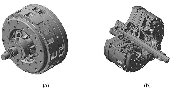
Figure 1.
3D model of the DCT: (a)—general view; (b)—cross-sectional view.
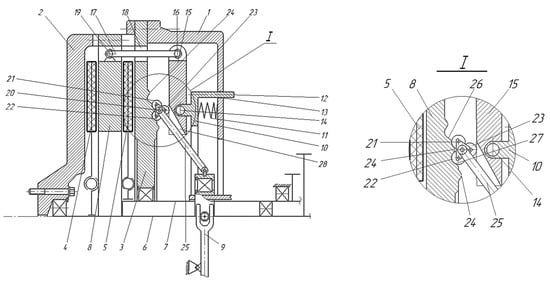
Figure 2.
The original DCT design: 1—casing; 2—flywheel; 3—platter; 4,5—driven discs; 6, 7—shafts; 8—pressure plate; 9—drive mechanism; 10—additional disc; 11—pressure springs; 12—elements; 13, 18—holes; 14, 16, 19—hinges; 15—rotary stops; 17, 25—levers; 20—movable supports; 21–23—rollers; 24—clamps; 26, 27—surfaces; 28—inclined grooves.
DCT contains casing 1 (mounted on the engine’s crankshaft through the leading flywheel 2), platter 3, driven discs 4 and 5 (mounted on splines on coaxially located main shafts 6 and 7), and shift drive mechanism 9. Flywheel 2 (used as drive disc), platter 3, and casing 1 are rigidly interconnected in the axial direction along the periphery, forming the driving elements of the clutches.
Between platter 3 and casing 1, additional disc 10 is installed in the axial direction. It is loaded with pressure springs 11 and moved through elements 12 with the possibility of interaction with holes 13. On an additional drive 10, from the platter side in the radial direction, stops 15 are fixed with hinges 14. They can rotate in radial planes. The ends of swivel stops 15 are connected with levers 17 from the periphery of the discs (in a horizontal plane) with hinges 16. The last ones (passed through holes 18 in platter 3 through hinges 19) are fixed on pressure plate 8. This plate has a possibility of forced axial movement.
The second free end of the rotary stops 15 interacts with movable supports 20. These supports are made as carriages with rollers 21, 22, and 23, placed between stops 15 and platter 3. The pair of rollers 21 and 22 on carriages can interact with clamps 24. Movable supports 20 are pivotally connected to drive mechanism 9 for switching clutches through levers 25.
The designed DCT operates as follows. In the switched-off (neutral) position, tdrive mechanism 9 is installed in such a way that the supports 20 are fixed in the middle position, excluding the rotation of stops 15 in the radial planes. Driven discs 4 and 5 do not interact with the leading flywheel 2, pressure plate 8, and platter 3. Main shafts 5 and 6 of even and odd gears rotate freely through driven discs 3 and 4 without transmitting torque from the engine.
When switching on the 1st clutch (Figure 2 and Figure 3), drive mechanism 9 is installed in such a way that the supports 20 move from the periphery of the discs to the rotation axis of the shafts through levers 25. In this case, support 20, overcoming the resistance of the clamps 24, moves along surface 27. It is installed in a fixed position, where torque occurs between hinges and rollers 23.
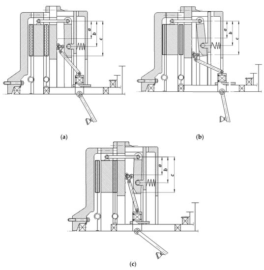
Figure 3.
Positions of the movable carriage of the control mechanism: (a)—neutral position; (b)—1st clutch; (c)—2nd clutch; a—length determining the position of the carriage under switched-on 2nd clutch, b—length determining the position of the carriage under switched-off 1st and 2nd clutches, c—length determining the position of the carriage under switched-on 1st clutch.
Additional disc 10 moves in the axial direction towards support disc 8 under the action of springs 11. Stops 15 transmit the pushing force to levers 17, turning on hinges 14 through hinges 16. Levers 7 transmit the force to pressure plate 8 through hinges 19. Pressure plate 8 acts on the driven disc 4 and flywheel 2. The friction pairs circuit for the 1st clutch closes. As a result, torque from the engine is transmitted to the input shaft 6 of the gearbox through drive flywheel 2, pressure plate 8, and drive plate 4.
When the 1st clutch is switched off, drive mechanism 9 is set to a position in which stops 20 moves to the periphery of the discs (Figure 2b and Figure 3b). In this case, rollers 21 and 22 move along surface 27, overcoming the resistance of clamps 24. These rollers are installed in a fixed position. However, rollers 23 are mounted on the same horizontal axis as hinges 14 of swivel stops 15 and pressure springs 11. Additional disc 10 moves in the axial direction away from support disc 3, overcoming the resistance of springs 11. Stops 15 transmit the pulling force to levers 17, turning on hinges 14 through hinges 16. Levers 17 transmit the force to pressure plate 8 through hinges 19. Pressure disc 8 opens the power circuit, stopping interaction with driven disc 3. As a result, the torque transmission from the engine to shaft 6 of the even rows of the gearbox stops.
When the 2nd clutch is switched on (Figure 2c and Figure 3c), mechanism 9 is located in such a way that stops 20 moves to the periphery through levers 25. In the rotary stops 15, inclined grooves 28 are made to ensure free movement of the levers 25. As a result, the contact of rollers 23 is ensured along one initial plane of stops 15. In this case, support 20 moves along surface 26, overcoming the resistance of clamps 24. Torque occurs between the axes of hinges 14 and rollers 23. Additional disc 10 moves in the axial direction towards support disc 3 under the action of compression springs 11. Stops 15 transmit the pulling force to levers 17, turning on hinges 14 through hinges 16. Levers 17 transmit the force to pressure plate 8 through hinges 19. Pressure disc 8 closes the power circuit, acting on driven disc 5 and platter 3. As a result, torque from the engine is transmitted to shaft 7 through pressure plate 8, driven disc 5, and support disc 3.
When the 2nd clutch is switched off, mechanism 9 is set to a position in which stops 20 move from the periphery of the discs to the center through levers 25 (Figure 3a). Rollers 21 and 22 move along inclined conical surface 26, overcoming the resistance of clamps 27. These rollers are installed in a fixed position. Rollers 23 are mounted on the same axis of horizontal hinge 14. The additional disc 10 is pushed into holes 13 of casing 1 through protrusions 12, overcoming the resistance of compression springs 11. They also move axially away from platter 3. In this case, stops 15 transmit the pushing force to levers 17, turning on hinges 14 through hinges 16. Levers 17 transmit the force to pressure plate 8 through hinges 19. Pressure disc 8 stops interacting with driven disc 5 and opens the circuit. As a result, the torque transmission from the engine to shaft 7 stops.
2.2. The Mathematical Model
A design model of the clutch shift mechanism is proposed to analyze the effect of DCT’s carriage movement on clutch margins (Figure 4).
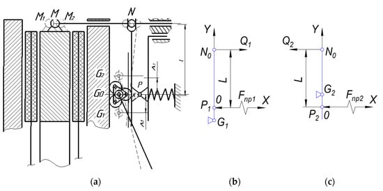
Figure 4.
The original DCT: (a)—the design scheme; (b)—1st clutch; (c)—2nd clutch.
The maximum engine torque, the clutch margin, and the number of friction pairs determine the required compression force Q for the clutch friction pairs. The clutch margin for the light vehicle is β = 1.2, 1.7–2.0 for all-terrain vehicles and 3.0 for heavy machinery. The calculation conditionally considers a single rotary lever and pressure spring. However, the number of levers can reach 3–4, and the number of springs can reach 18–42, depending on the transmitted engine torque.
The total pressing force Fnp is summarized by all the pre-compressed springs. It is conventionally attached to the clutch swing lever NP, which is connected to the clutch pressure plate via trailing lever NM at point M. When moving the carriage from position G0 to positions G1 and G2, the pressure plate moves from position M to positions M1 and M2 (Figure 3a). The action line of the total force Q coincides with the lever NM. It is also located at a distance L from the pressure spring line of action.
The coordinate system XOY is used to study the clutch operation. The axis OX is directed along the compression spring action line. The axis OY is directed along the swivel disc in its neutral position ON0. The full switch-on of the clutch is considered. Vertical lines M1 and M2 determine the extreme positions of the friction pressure plates for the switched-on 1st and 2nd clutch, respectively, with coordinates xM1 and xM2.
A pre-compressed pressure spring is used to provide the required force Q. The proposed design scheme allows determining dependencies between the force Qj (j = 1, 2) on the pressure plate and force Fnpj of the clutch pressure spring when switching on the 1st (Figure 3b) and the 2nd (Figure 3c) clutch, so during vertical movement of the carriage from the neutral position G0 to working positions Gj by the distance of ΔKj (Figure 3a).
The equilibrium condition of the j-th lever relative to the reference point Gj is as follows:
or for the cases of switching on the 1st and the 2nd clutches, respectively:
from which the following expressions can be obtained:
where the following parameter is introduced:
Formula (3) shows that the inequality Fnp1 > Fnp2 ensures equal forces on the pressure disc (Q1 = Q2 = Q) in the case of similar carriage movements. To fulfill this condition, the design schemes in Figure 5 are considered.

Figure 5.
The design schemes of the switched-on DCT: (a)—1st clutch; (b)—2nd clutch.
When the support carriage G is moved to position Gj, the support lever rotates under the force Fnpj from the pressure spring at point Pj. This fact provides the required compression force Qj of the clutch friction pairs. For this case, pressure spring forces on the platter surface will be as follows:
where cnp—compression spring stiffness [kN/mm]; Δ0—spring pre-deformation [mm] for the neutral position of the carriage (when clutches are switched off); Δj—additional deformation of the pressure spring when turned on the j-th clutch (from Figure 4, Δ1 = OP1, Δ2 = OP2). Particularly, after switching on the 1st clutch (Figure 4), the rotary lever reaches the position NjGj, where xN1 = –z1. Gap neglecting zc1 occurs for the freewheel, and elastic deformation of friction linings equals zy1. Therefore, z1 = zc1 + zy1.
Assuming that the lever NjGj does not deform, the following geometric expression can be written:
where αj—j-th lever angle [deg], determined from the equation:
Thus, Equation (5) can be rewritten as follows:
The dependencies (1)–(8) allow studying the switching-on clutches in the DCT.
3. Results
Figure 6 shows the effect of carriage displacement ΔK on the force Fnpk in the pressure spring and the force Qk on the pressure disc when switching on the k-th clutch.
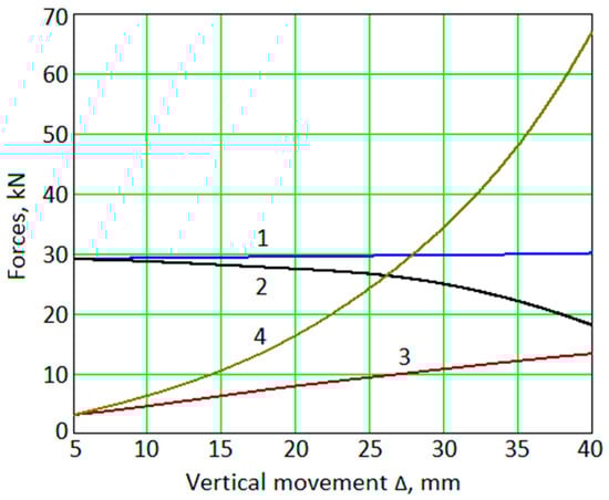
Figure 6.
Dependencies of forces Qk and Fnpk [kN] on the pressure disc (1,2) and spring (3,4) on the vertical movement Δ [mm] of the carriage: 1—Fnp1; 2—Q1; 3—Fnp2; 4—Q2.
A dry clutch is considered a test case for simulating the DCT workflow. This clutch is widely used in the automotive and agricultural industries. It also has the following parameters: L = 0.053 m, z1 = z2 = z = zc + zy, zc = 2.0 mm, zy = 0.8 mm, c = 950 kN/m, Δ0 = 30 mm.
The analysis results presented in Figure 6 shows that the force on the pressure plate will be different for a uniform vertical movement of the carriage ΔK (when switching on the 1st and the 2nd clutches). Moreover, Q2 > Q1 and Fnp2 > Fnp1. In this case, Fnp1 changes insufficiently.
An increase in ΔK increases the difference Q21 = Q2—Q1 between forces on the pressure disc and decreases the clutch margin. Notably, such a difference in the pressure disc also increases but is lower. Hence, it is not possible to provide the same clutch margin. Moreover, equality Q1 = Q2 cannot be provided by choosing different carriage displacements (ΔK1 ≠ ΔK2).
Therefore, to equalize the clutch margin, it is proposed to abandon the strictly vertical movement of the carriage. It is also suggested to constructively realize an additional horizontal movement of the carriage. In this case, to equalize forces QK1 and QK2, the force QK1 should increase, and the force QK2 should be decreased. The corresponding change in the position of points P1 and P2 of the carriage contact with the pressure spring can achieve the last condition. In other words, the platter profile along which the carriage moves under switching on/off the DCT should be changed.
In the proposed improved DCT design [32], rollers 21 and 22 move on the inclined conical surfaces 26 and 27 of the support disc. The corresponding design schemes are presented in Figure 7.
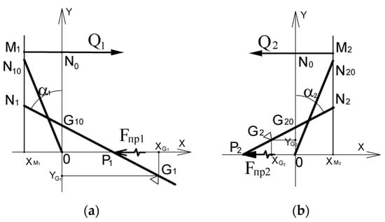
Figure 7.
Design schemes of the improved DCT: (a)—1st clutch; (b)—2nd clutch.
It is convenient to characterize the clutch operation when the k-th clutch is switched on by changing the position of the rotary lever NkPk with the inclination angle αk. The extreme positions of the friction pressure plates are conditionally marked by vertical lines Mk. Point Nk of the rotary lever has the coordinate xMk = const.
The following dependencies determine the coordinates of characteristic points Nk and Pk for the swivel disc:
where zk = |xMk|.
When the clutch is entirely switched on, gap neglect occurs, and the friction linings are elastically deformed. Therefore, the initial position of the rotary lever (at the initial position of the carriage G0) can be represented by levers ON10 and ON20. In this case, xN10 = xM1, xN20 = xM2, and the initial inclination of the rotary disc is characterized by angles α10, α20.
At a specific position of the rotary lever, the carriage position is determined from the following expressions:
where ΔKk—vertical movement of the carriage [mm].
The pressing force Qk of the friction pairs and the force Fnp1 from the pressure spring (when the j-th clutch is switched on) are determined by Formulas (5)–(8).
The current deformation Δk of the pressure spring (the value of OPk) is determined by the coordinate xPk For the investigated clutch design (Figure 1b), under the switching-off of the 1st clutch, the pressure spring is additionally compressed (Δ1 > 0). For the 2nd clutch, the force in the pressure spring is decreased (Δ2 < 0). This fact increases the value of Q1 and decreases the value of Q2.
Figure 8 shows the impact of specified horizontal carriage displacement (considered by the angle αk) with a vertical displacement of the carriage by Δk = ∓15 mm for the considered case study.
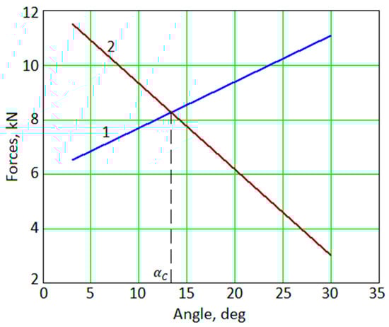
Figure 8.
Dependencies of forces Qk [kN] on the lever rotation angle αk [deg]: 1—Q1; 2—Q2.
As the study results show, after considering the horizontal displacement of the carriage, an increase in the angle αk (an increase in the value of |xGk|) decreases Q2 and increases Q1. However, despite the previous design scheme when xGk = 0, the following equality Q2 = Q1 takes place under a specific value of the angle αc. Therefore, the problem of equality for the clutch margins has been solved.
Figure 9 shows results on changes in the forces Q1(α1) and Q2(α2) on the pressure disc at different values of vertical displacements of the carriage ΔK = 5–30 mm with a step of 5 mm.
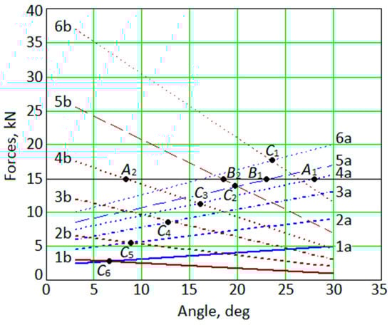
Figure 9.
Dependencies of Qk(αk) on the angle α [deg] for different displacements Δ [mm]: a—Q1; b—Q2; 1—Δ = 5 mm; 2—Δ = 10 mm; 3—Δ = 15 mm; 4—Δ = 20 mm; 5—Δ = 25 mm; 6—Δ = 30 mm.
After applying the obtained results, it is possible to select the k-th position of the rotary lever and, accordingly, the position of the support carriage, which provide equal friction coefficients (since Q1 = Q2) in the case of choosing similar vertical displacements of the carriage (ΔK1 = ΔK2) when the clutches are switched on.
Particularly, ensuring equal forces on the pressure plate (Q1 = Q2 = 15 kN) under the switched-on clutches 1 and 2 can be realized using the vertical movement of the carriage by ΔK1 = ΔK2 = 20 mm (points A1, A2) or through vertical displacement by ΔK1 = ΔK2 = 25 mm (points B1, B2). The levers’ positions (angles α1 and α2) are different in this case. This complicates surface treatment technology for the platter on which the carriage moves and the corresponding control system.
However, as the results show, this shortcoming can be overcome. Particularly, for the chosen vertical movement ΔK of the carriage, the lever position (points Ci, I = 1, 2, …, 6) can be determined to satisfy the following equalities: Q1(Ci) = Q2(Ci), α1(Ci) = α2(Ci) =α(Ci). This case corresponds to equal ratios for the 1st and 2nd friction clutches. It also facilitates the platter surface design on which the carriage moves.
Figure 10 shows the results for the dependencies between the forces difference Q21 = Q2 − Q1 (on the pressure plate) and the corner α = α1 = α2 for some values of vertical movements ΔK = ΔK1 = ΔK2 of the carriage.
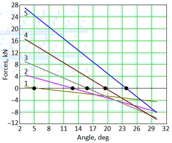
Figure 10.
Dependencies of Q21(α21) [kN] on the displacement Δ [mm]: 1—Δ = 5 mm; 2—Δ = 10 mm; 3—Δ = 20 mm; 4—Δ = 25 mm; 5—Δ = 30 mm.
When synthesizing the clutch control mechanism, based on the conditions ΔK = ΔK1 = ΔK2 for providing the equal position of the rotary lever (α1 = α2 = αc), the primary attention should be focused on the results presented in Figure 11.
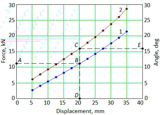
Figure 11.
Dependencies of Q(ΔK) [kN] (1) and αc(ΔK) [deg] (2) on the displacement Δ [mm].
Based on the required loading QP for the clutch friction pair compression, values for the carriage movement ΔK and the inclination angle αc should be chosen properly. Such a rational choice allows for designing the clutch disc’s surface profile, providing equal ratios for the 1st and 2nd clutches. The following case study illustrates this. Let the required force QP = 11 kN be given, which corresponds to point A (Figure 11). Furthermore, point B (on the curve Q) should be found, which corresponds to the vertical movement ΔK1 = ΔK2 = ΔK = 20 mm of the carriage (point D). This point D allows determining point C (on the curve ) and the angle αc = 16° (point E).
Suppose that according to the conditions of the task, it is required to change the force QP. In that case, new values of ΔK and αc can be similarly determined, or the calculated values ΔK = 20 mm and αc = 16° can be left (which correspond to the force Q* = 11 kN), but the stiffness cnp of the pressure spring should be changed χ = Q*/QP times.
Remarkably, when choosing the vertical displacement ΔK of the carriage, the following limits should be considered: ΔK2 < ΔK2max, where ΔK2max = Δzc + yK2max (Figure 12).

Figure 12.
Limitation for the vertical displacement Δk2max [mm] of the carriage for different values of the angle α [deg] when the 2nd clutch is switched-on (L = 53 mm and z = 2.8 mm).
The above recommendations are mainly related to ensuring the equal vertical movement of the carriage (ΔK = ΔK1 = ΔK2) when switching on the clutch. However, there may be other criteria for synthesizing the clutch control mechanism. Particularly, if there is a need to ensure the equal displacement (S1 = S2) of the carriage, these displacements should be determined as follows:
where , —coordinates of the carriage on the platter surface.
In this case, the equation of a straight line that passes through the points NK and PK (Figure 4) should be written as follows:
Using expressions (9) for the coordinates of points and , this dependence can be rewritten as follows:
The movement of the carriage equals SK [mm]. Therefore, point GK(xGk, yGk) is placed both on the circle SK and straight line NkPk:
The solution of this system allows determining the angle αK of the rotary lever for carriage located at point GK(xGk, yGk) on the distance of SK, using parameters αK and ΔK = y(Gk).
However, to synthesize the surface profile of the support disc, it is more convenient to use the polar coordinate system (Sk, βk), where βk is the angular coordinate (Figure 13):
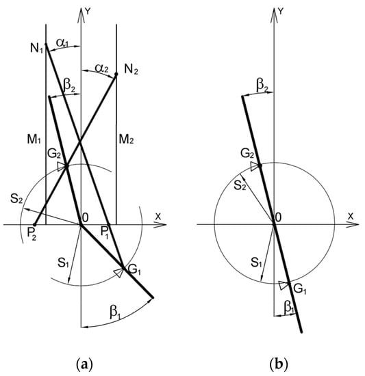
Figure 13.
The conical contact surface of the platter: general (a) and simplified (b) case studies.
After considering the issues of simplifying the technology of manufacturing a conical surface, the clutch control system can be simplified using the following limitation:
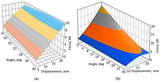
Figure 14.
Surfaces QK = Q(S1, β1) [kN] (a) and QK = Q(S2, β2) [kN] (b) on the displacement Sk [mm] and the angle βk [deg].
The results show that condition (16) can be satisfied. Particularly, the locus of these points that meets this condition is presented in Figure 15.
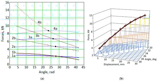
Figure 15.
Dependencies of Qk(Sk, βk) [kN] (a) and Q(S, β) [kN] (b) on the displacements S, Sk [mm] and the angle βk and β [deg]: a—Q1; b—Q2; 1—S = 5 mm; 2—S = 10 mm; 3—S = 15 mm; 4—S = 20 mm.
The synthesis results presented in Figure 16 are also of interest. Particularly, it demonstrates the dependence of the carriage movement on the force acting on the pressure disc.
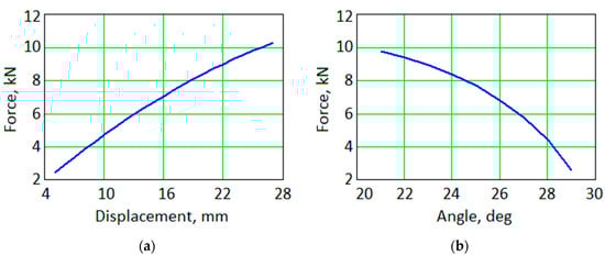
Figure 16.
Dependencies of the forces Q [kN] on the displacement Sk (a) and the angle β [deg] (b).
Notably, the maximum carriage movement depends on the length L of the rotary lever and the parameter z. For the considered case study, S < 24.5 mm.
The minimum carriage movement Smin is determined by the wear resistance of the carriage movement mechanism. In this case, the inclination angle of the surface profile of the platter is in the range of β = 20–29° (Figure 16).
Finally, the carried-out research, the developed methodology, and the corresponding algorithm allow for designing the platter surface profile for the DCT, providing equal clutch margins (Figure 17).
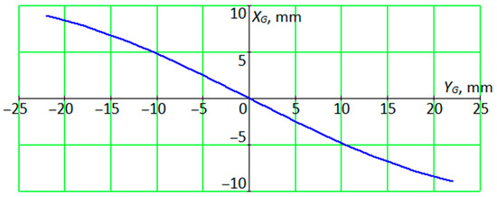
Figure 17.
Clutch platter surface profile for equal clutch factors in coordinates XG, YG [mm].
4. Discussion
Comparing the proposed DCT with traditional dual-clutch designs, it can be summarized that it has a reduced energy consumption for clutch control. Particularly, in a fairly common dry dual clutch of the automotive industry, each clutch is switched on by a pressure plate and actuator. The drive of such a clutch uses a separate mechanism and actuator (hydraulic cylinder) connected through a distributor to a pump. This requires additional energy costs. Remarkably, energy is permanently spent on maintaining the clutch in the switched-on position. However, there are no shortcomings in the proposed DCT.
Thus, the considered dry DCT provides fast and practically uninterruptible power flow from the DCT through the clutch. This can improve the vehicle’s acceleration dynamics and reduce the energy costs of switching clutches.
Nevertheless, the kinematic and dynamic analyses of the device [33] showed that the loading of the driven discs for each clutch is uneven. Particularly, clutch margins when switching are different. This impacts the service life of each clutch and dynamic processes in the vehicle’s transmission.
The novelty of the research is in the substantiation of the mathematical model, the development of the methodology, and the related algorithm for choosing the rational design parameters of the DCT and its drive. This increases the functional performance of the unit while reducing energy costs for control.
The practical significance of the results is to substantiate the possibility of increasing the efficiency of the original DCT. It is also in developing recommendations for determining the rational design parameters and the algorithm’s versatility when designing such clutches for automotive, agricultural, and other industries.
5. Conclusions
In the article, the working processes in DCTs have been analyzed. A functional relationship has been established between the drive control parameters and the pressure forces (load capacity) on the clutch friction pairs. The impact of the vertical movement of the control carriage has also been analyzed.
It has been established that only vertical movement of the control carriage does not provide the equality of the clutch margins for the 1st and the 2nd clutch with the equal movement of the carriage.
As a result, a methodology for synthesizing the parameters of the DCT control mechanism has been proposed. The proposed approach is oriented towards the transmission of the required clutch torque. The proposed design solution for the control mechanism substantiates the equalization of the load capacity of the clutch.
The problem of synthesizing the parameters of the surface profile of the disc has also been solved. It allows for providing the equality of clutch margins for the 1st and 2nd clutches. However, the functional limitation regarding the equality of vertical (radial) movements or the general carriage movement for the control mechanism should be satisfied.
The economic effect from the implementation of the obtained results is primarily associated with a decrease in the energy losses of the internal combustion engine and the costs of a vehicle’s driver during the operation. The efficiency of the proposed novel clutch is also due to the achievement of the same operating conditions for each clutch. Mainly, equal wear rates of friction pairs and dynamics equalization of the drive wheels (when switching clutches and transmitting the torque of the engine) have been provided. This extends the service life of the clutch and transmission, decreases fuel consumption, and improves the vehicle’s environmental safety, traction, and dynamic performance.
Further studies will aim to generalize the proposed algorithm for synthesizing parameters of various types of DCT control mechanisms. Particularly, as part of the strategic problem of the systematic improvement of the vehicle’s quality, it is planned to develop a multi-criteria optimization approach considering economic, energy, and environmental quality indicators. This will allow for the optimal design of DCTs with an extended number of parameters.
Author Contributions
Conceptualization, N.S.; methodology, P.K.; software, I.P.; validation, M.O. and I.P.; formal analysis, A.S., A.K., M.M. and S.W.; investigation, N.P. and I.P.; resources, Y.B. and A.K., M.M. and S.W.; data curation, O.T.; writing—original draft preparation, I.P.; writing—review and editing, A.N., M.O. and S.W.; visualization, I.P. and V.I.; supervision, V.I.; project administration, I.P.; funding acquisition, M.O. All authors have read and agreed to the published version of the manuscript.
Funding
The publication was funded by the Polish Ministry of Education and Science (SBAD).
Institutional Review Board Statement
Not applicable.
Informed Consent Statement
Not applicable.
Data Availability Statement
Not applicable.
Acknowledgments
The results were partially obtained at Poznan University of Technology within the project “Application of artificial intelligence system for diagnostics and predictive maintenance of rotary machines” of the Ulam NAWA Programme ordered by the Polish National Agency for Academic Exchange, grant number BPN/ULM/2022/1/00042. The authors also acknowledge the International Association for Technological Development and Innovations for support while conducting the research.
Conflicts of Interest
The authors declare no conflict of interest.
References
- Xu, X.; Dong, P.; Liu, Y.; Zhang, H. Progress in automotive transmission technology. Automot. Innov. 2018, 1, 187–210. [Google Scholar] [CrossRef]
- Shevchenko, S.; Mukhovaty, A.; Krol, O. Gear clutch with modified tooth profiles. Procedia Eng. 2017, 206, 979–984. [Google Scholar] [CrossRef]
- Sankaranayanan, V.; Emekli, M.E.; Gilvenc, B.A.; Guvenc, L.; Ozturk, E.S.; Ersolmaz, E.S.; Eyol, I.E.; Sinal, M. Semiactive suspension control of a light commercial vehicle. IEEE/ASME Trans. Mechatron. 2008, 13, 598–604. [Google Scholar] [CrossRef]
- Tripathi, K. Some design-objectives and design-guidelines for automotive friction clutch based on clutch engagement dynamics. J. Inst. Eng. India Ser. C 2014, 95, 51–61. [Google Scholar] [CrossRef]
- Pisaturo, M.; Senatore, A. Thermal compensation control strategy in automated dry clutch engagement dynamics and launch manoeuvre. Int. J. Automot. Technol. 2019, 20, 1089–1101. [Google Scholar] [CrossRef]
- Minas, I.; Morris, N.; Theodossiades, S.; O’Mahony, M.; Voveris, J. Automotive dry clutch fully coupled transient tribodynamics. Nonlinear Dyn. 2021, 105, 1213–1235. [Google Scholar] [CrossRef]
- Fan, X.; Walker, P.D.; Wang, Q. Modeling and simulation of longitudinal dynamics coupled with clutch engagement dynamics for ground vehicles. Multibody Syst. Dyn. 2018, 43, 153–174. [Google Scholar] [CrossRef]
- Chen, Y.; Wang, X.; He, K.; Yang, C. Model reference self-learning fuzzy control method for automated mechanical clutch. Int. J. Adv. Manuf. Technol. 2018, 94, 3163–3172. [Google Scholar] [CrossRef]
- Deng, T.; Hu, F.; Lu, R. Research on DCT shifting torque control and a benchmark test. J. Mech. Sci. Technol. 2015, 29, 3581–3589. [Google Scholar] [CrossRef]
- Pourgol-Mohammad, M.; Hejazi, A.; Soleimani, M.; Ghasemi, P.; Ahmadi, A.; Jalali-Vahid, D. Design for reliability of automotive systems; case study of dry friction clutch. Int. J. Syst. Assur. Eng. Manag. 2017, 8, 572–583. [Google Scholar] [CrossRef]
- Park, J.; Choi, S. Optimization method of reference slip speed in clutch slip engagement in vehicle powertrain. Int. J. Automot. Technol. 2021, 22, 55–67. [Google Scholar] [CrossRef]
- Lucente, G.; Montanari, M.; Rossi, C. Modelling of an automated manual transmission system. Mechatronics 2007, 17, 73–91. [Google Scholar] [CrossRef]
- Senatore, A. Advances in the automotive systems: An overview of dual-clutch transmissions. Recent Pat. Mech. Eng. 2009, 2, 93–101. [Google Scholar] [CrossRef]
- Yang, Y.-V.; Zhu, Z.-B.; Wang, X.-Y.; Chen, Z.; Ma, Z.-L. Optimal launching-intention-aware control strategy for automated clutch engagement. Int. J. Automot. Technol. 2017, 18, 417–428. [Google Scholar] [CrossRef]
- Van Der Heijden, A.C.; Serrarens, A.F.; Camlibel, M.K.; Nijmeijer, H. Hybrid optimal control of dry clutch engagement. Int. J. Control 2007, 80, 1717–1728. [Google Scholar] [CrossRef]
- Glielmo, L.; Iannelli, L.; Vacca, V.; Vasca, F. Gearshift control for automated manual transmissions. IEEE/ASME Trans. Mechatron. 2006, 11, 17–26. [Google Scholar] [CrossRef]
- Ma, K.; Sun, D.; Sun, G.; Wang, D. Wet dual clutch launching adaptive control considering service time. J. Mech. Sci. Technol. 2022, 36, 2759–2773. [Google Scholar] [CrossRef]
- Glielmo, L.; Gutman, P.O.; Iannelli, L.; Vasca, F. Robust Smooth Engagement of an Automotive Dry Clutch. IFAC Proc. Vol. 2006, 39, 632–637. [Google Scholar] [CrossRef]
- Deng, T.; Hu, F.B.; He, Z.Y.; Yin, Y.L. Simulation, experimental testing and optimization of starting and shifting control strategies of DCT wet dual clutches with respect to sliding friction. Iran. J. Sci. Technol. Trans. Mech. Eng. 2019, 43, 693–705. [Google Scholar] [CrossRef]
- Cho, J.; Lee, Y.; Kim, W.; Jang, S. Wet single clutch engagement behaviors in the dual-clutch transmission system. Int. J. Automot. Technol. 2018, 19, 463–472. [Google Scholar] [CrossRef]
- Pica, G.; Cervone, C.; Senatore, A.; Lupo, M.; Vasca, F. Dry dual clutch torque model with temperature and slip speed effects. Intell. Ind. Syst. 2016, 2, 133–147. [Google Scholar] [CrossRef]
- Zhu, M.; Yao, P.; Pu, Y.; Liu, T. Comparative study on the temperature rise of a dry dual clutch under different starting conditions. Automot. Innov. 2019, 2, 35–44. [Google Scholar] [CrossRef]
- Abdullah, O.I.; Schlattmann, J. Thermal behavior of friction clutch disc based on uniform pressure and uniform wear assumptions. Friction 2016, 4, 228–237. [Google Scholar] [CrossRef]
- Bukashkin, A.Y.; Dobretsov, R.Y.; Galyshev, Y.V. Split transmission of tractor with automatic gearbox. Procedia Eng. 2017, 206, 1728–1734. [Google Scholar] [CrossRef]
- Darko, S.; Spasojevic, V.; Stevanovic, I. The contemporary automatic gearboxes—Review of the current state and interpretation of advantages and disadvantages of their use with respect to vehicle performance and traffic safety. Istraz. Proj. Privredu 2013, 11, 89–97. [Google Scholar] [CrossRef]
- Gkinis, T.; Rahmani, R.; Rahnejat, H.; O’Mahony, M. Heat generation and transfer in automotive dry clutch engagement. J. Zhejiang Univ. Sci. A 2018, 19, 175–188. [Google Scholar] [CrossRef]
- Hebbale, K.; Samie, F.; Kish, J. Dry dual clutch transmission (DCT) thermal model. In Proceedings of the SAE 2015 World Congress & Exhibition, Detroit, MI, USA, 21–23 April 2015; SAE Technical Paper. SAE International: Warrendale, PA, USA, 2015. [Google Scholar] [CrossRef]
- Romanchenko, O.; Sokolov, V.; Krol, O.; Baturin, Y.; Stepanova, O. Automatic control of electrohydraulic drive for technological equipment. In Proceedings of the International Conference on Reliable Systems Engineering (ICoRSE) 2022, Bucharest, Romania, 8–9 September 2022; Lecture Notes in Networks and Systems. Cioboată, D.D., Ed.; Springer: Cham, Switzerland, 2023; Volume 534, pp. 329–337. [Google Scholar] [CrossRef]
- Grzelczyk, D.; Awrejcewicz, J. Wear processes in a mechanical friction clutch: Theoretical, numerical, and experimental studies. Math. Probl. Eng. 2015, 2015, 725685. [Google Scholar] [CrossRef]
- Vanyeyev, S.M.; Miroshnichenko, D.V.; Rodymchenko, T.S.; Protsenko, M.; Smolenko, D.V. Data measuring system for torque measurement on running shafts based on a non-contact torsional dynamometer. J. Eng. Sci. 2019, 6, E15–E23. [Google Scholar] [CrossRef]
- Sergienko, M.Y.; Sergienko, A.M.; Khudolii, O.I. Two-Loop Friction Clutch. Patent for an Invention of Ukraine No. 101,711, 25 April 2013. [Google Scholar]
- Sergienko, M.Y.; Sergienko, A.M.; Khudolii, O.I.; Sergienko, D.Y.; Pavlova, N.M.; Maidaniuk, V.G.; Zarubina, A.O.; Svidlo, V.S. Two-Loop Friction Clutch. Patent for an Invention of Ukraine No. 125,475, 23 March 2022. [Google Scholar]
- Sergienko, N.; Kalinin, P.; Gasanov, M.; Pavlova, N.; Svidlo, V.; Okun, А. Analysis of the parameters of the double clutch drive with reduced control energy consumption. Bull. Natl. Tech. Univ. “KhPI” Ser. New Solut. Mod. Technol. 2021, 4, 49–60. [Google Scholar] [CrossRef]


Disclaimer/Publisher’s Note: The statements, opinions and data contained in all publications are solely those of the individual author(s) and contributor(s) and not of MDPI and/or the editor(s). MDPI and/or the editor(s) disclaim responsibility for any injury to people or property resulting from any ideas, methods, instructions or products referred to in the content. |
© 2023 by the authors. Licensee MDPI, Basel, Switzerland. This article is an open access article distributed under the terms and conditions of the Creative Commons Attribution (CC BY) license (https://creativecommons.org/licenses/by/4.0/).