Abstract
In this paper, a computational fluid dynamics simulation method is developed to study the influence of the rotor overlapping azimuth on the aerodynamic performance of compound coaxial helicopter. The simulation method is verified by comparing the numerical simulation results with the wind tunnel experiment data of the NASA coaxial rotor. Two overlapping azimuths of the upper and lower blades are considered, and the aerodynamic performance of the isolated rotor and the compound coaxial helicopter in hover and forward are analyzed respectively. State 1 means the upper and lower blades overlap at azimuth or , state 2 means the upper and lower blades overlap at azimuth or . It is found that the performance of isolated rotors is not affected by rotor overlapping azimuth in hover, but the total thrust fluctuation amplitude of isolated rotors in state 2 is 76.3% smaller than that in state 1 in forward. In the hovering flight of compound coaxial helicopter, compared with state 1, the fluctuation amplitude of the lift of the wing in state 2 is 42.7% smaller; the lift fluctuation amplitude of the flat tail in state 2 is 52.4% smaller. In the forward flight of compound coaxial helicopter, compared with state 1, the total thrust fluctuation amplitude in state 2 is 83.5% smaller; the fluctuation amplitude of the lift of the wing in state 2 is 61.2% smaller. It can be concluded that the compound coaxial helicopter working in state 2 has better aerodynamic performance than the compound coaxial helicopter working in state 1; changing the rotor overlapping azimuth of the upper and lower rotors has a high engineering application value, which can increase aerodynamic stability and reduce lift fluctuations.
1. Introduction
The helicopter has the characteristics of vertical take-off and landing, hovering, and near-ground maneuverability, which plays an important role in military and civilian fields [1,2]. For conventional helicopters, the forward flight speed is restricted by the dynamic stall of the retreating blade and the compressibility of the advancing blade. The compound helicopter has become a solution to increase the forward speed of the helicopter. At present, coaxial rigid rotor compound helicopters and tilt-rotor aircraft have been developed rapidly [3,4,5,6].
The compound helicopter with a rigid coaxial rotor is one of the main configurations in the development of high-speed helicopters, and as the most important feature of the helicopter, the Advanced Blade Concept (ABC) rotor is adopted [7,8,9,10]. The coaxial rigid rotor high-speed helicopter adopts the coaxial main rotor with upper and lower rotors reversed and tail thrust propellers. The dynamic stall on the retreating blade is weakened by the lift offset of the rigid rotor, and the fuselage drag is overcome by the thrust propeller to achieve high-speed forward flight [11]. Sikorsky X2 and S-97 [12] are typical of compound helicopters.
The research on the aerodynamic performance of helicopter rotors mainly includes the experimental method and CFD method [13,14,15]. The advantages of the experimental method are direct and reliable, while the disadvantages are long cycles and high costs. The computational fluid dynamics (CFD) method is developing rapidly. Its advantages are low cost, short period, and high precision. At present, CFD has become an important method of helicopter aerodynamic performance research [16,17,18].
At present, CFD technology has been widely used in the aerodynamic simulation of helicopter rotors. Overset grid method is applicable to helicopter hovering, forward flight, vertical flight, near-ground flight, and other complex flights, which is one of the most widely used methods in this field. Ruzicka [19] used the overset grids to study the interaction flow field of coaxial rotors. Compared with the flow field calculation of a single rotor, the calculation model is more complex and the calculation amount is larger. Berry et al. [20] conducted an experimental study of the rotor/fuselage flow field. Shibliyev et al. [21] used the overset mesh approach to study helicopter unsteady flow problems, which were tested on a generic helicopter configuration in terms of load balance, scalability, and memory usage. Boyd et al. [22] adopted an unsteady rotor-fuselage interactional aerodynamics model to calculate the flow field of ROBIN rotor fuselage. Bhattacharyya et al. [23,24] calculated the rotor flow field characteristics under the influence of the ground with the structure grid, which took into account the unsteady influence of moving blades on the flow field. Strawn et al. [25,26] used unstructured grids to solve the hovering flow field of rotors. Kang & Kwon [27] used unstructured grids and Navier-Stokes (N-S) equations to simulate the rotor flow field in hover. Shenoy et al. [28] presented anisotropic grid adaptation for dynamic overset simulations to study rotor/fuselage-interaction flow field. Wang et al. [29] studied the three-dimensional effects on the dynamic-stall characteristics of a rotor blade, which filled the gap regarding the insufficient three-dimensional dynamic stall of a helicopter rotor. Batrakov et al. [30] used CFD modeling to compute the unsteady flow around the main rotor-fuselage. Zhao et al. [31] applied a high-resolution air load with accurate rotor wake to study rotor BVI (Blade-vortex interaction) analysis. Deng et al. [32] focused on aerodynamic characteristics of rigid coaxial rotor of a high-speed helicopter in hover and forward flights in the 8 m×6 m low-speed straight flow wind tunnel of China Aerodynamics Research and Development Center. Zhou et al. [33] developed the polyhedral nested grid to study the interference flow field of the Robin rotor/fuselage. Boisard et al. [34] developed a full computational fluid dynamics (CFD) unsteady computation to better capture all the unsteadiness of the interaction. Giljarhus et al. [35] investigated of rotor efficiency with varying rotor pitch angles for a coaxial drone. Kim et al. [36] carried out performance analysis for a 1.8 m diameter propeller for use in a multicopter-type Personal Air Vehicle (PAV) with a Maximum Take-Off Weight (MTOW) of 600 kg. Steven et al. [37] studied Interactional aerodynamics for counter-rotating coaxial rotors in hover.
The purpose of the paper is to study the influence of the upper and lower rotor overlapping azimuth on compound coaxial helicopter performance. Polyhedron nested grid has the advantages of fewer meshes, faster convergence speed, and higher calculation accuracy. In this paper, the aerodynamic performance of a compound coaxial helicopter in hover and forward flight was simulated using polyhedron nested grids. The numerical results calculated by CFD method were compared with NASA wind tunnel test data to validate the accuracy of CFD simulation. The performance of a compound coaxial helicopter was calculated and analyzed under different overlapping azimuths of the upper and lower rotor.
2. CFD Simulation Method
2.1. Governing Equation and Solution Method
In order to improve the accuracy of the calculation flow field, the N-S governing equations considering the gas viscosity and compressibility are used to solve the rotor flow field. Considering the continuity equations, momentum equations, and energy equations comprehensively, the conserved Reynolds-averaged Navier-Stokes equation of three-dimensional, viscous, unsteady, and compressible flow in the inertial coordinate system can be obtained:
where, is the conservation variable, is the convection flux, and is the viscous flux.
Shear-Stress Transport (SST) K-Omega turbulence model [16] was used to estimate the eddy viscosity of the flow field. The problem of sensitivity to free-stream/inlet conditions was addressed by SST turbulence model. The SST model has seen fairly wide application in the aerospace industry, where viscous flows are typically resolved, and turbulence models are applied throughout the boundary layer.
The turbulent eddy viscosity is calculated as:
where, is the density, T is the turbulent time scale.
The transport equations for the kinetic energy and the specific dissipation rate are:
where, is the mean velocity, is the dynamic viscosity, and are model coefficients, and are production terms, is the free-shear modification factor, is the vortex-stretching modification factor, and are the user-specified source terms, and are the ambient turbulence values that counteract turbulence decay.
The advection upstream splitting method (AMSM) format in the upwind format is adopted. This format has both high computational efficiency and intermittent high resolution, low numerical dissipation and no entropy correction is required.
Assuming that the unit volume of each control body does not change with time,
and the rotor is in the forward flight,
where, is net flux on the boundary.
In this paper, the dual-time advance method with higher computational efficiency is selected for time discretization, and the Runge-Kutta explicit solution method is used in the sub-iteration process. Jameson [38] explained in detail the dual-time method when using explicit advance.
Figure 1 shows the flow chart of the dual-time advance format using the motion nested grid. This time-advance method is widely used in the unsteady CFD simulation of the rotor.
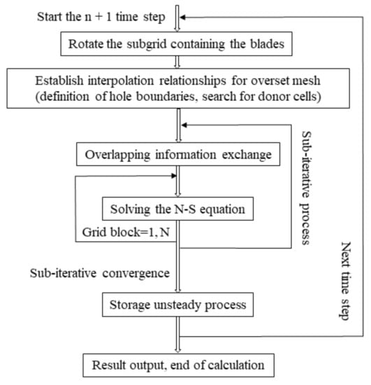
Figure 1.
Flow diagram of the dual-time stepping method for overset grid.
When calculating the rotor flow field in the hovering flight, the initial conditions are as shown below:
When calculating the rotor flow field in the forward flight, the initial conditions as shown below:
The boundary conditions involved in the numerical simulation of the helicopter rotor flow field mainly include the object surface boundary conditions and the far field boundary conditions.
The boundary of the object’s surface is mainly the surface of the blade. When the N-S equations are adopted, the relative velocity between the airflow at the object surface and the motion of the blade is zero, as shown below:
where, and are the velocity of the fluid at the surface of the blade and the velocity of the surface of the blade, respectively.
The normal gradient of the temperature and pressure on the surface of the blade is zero, as shown below:
The inflow and outflow boundaries of the helicopter flow field are generally subsonic. is Riemann invariants. For the subsonic inflow and outflow, is calculated by interpolation between the inner and outer fields, and is calculated by the value of the incoming flow at infinity, as shown below:
The normal velocity and sound velocity on the boundary:
Subsonic inflow boundary ():
Subsonic flow boundary ():
where, is the outward normal velocity of the far field boundary, is the local speed of sound, and is the specific heat capacity. is the tangential velocity, is the entropy. The subscripts and represent the incoming flow value and the internal field value, respectively.
A non-dimensional wall distance for a wall-bounded flow can be defined in the following way:
where is the friction velocity at the nearest wall, is the distance to the nearest wall and is the local kinematic viscosity of the fluid.
2.2. Grid System
In this paper, an O-type mesh is selected as the blade body-fitted structured mesh. The two-dimensional section of the blades is distributed along the radial direction in an H shape, and finally an O-H blade body-fitted structured grid is formed, as shown in Figure 2. The advantage of using the H-shaped distribution is that the blade body-fitted structured grid has a high grid quality, and it is not easy to produce grid distortion. At the same time, this type of grid has high computational efficiency. In order to simulate the separation of the blade tip shock wave and the airflow separation near the blade root, the mesh of the blade tip has been refined in the radial direction. The body-fitted structured grid surrounding the blade belongs to the foreground grid in the nested grid system and meets the requirements of forming a nested relationship with the background grid.
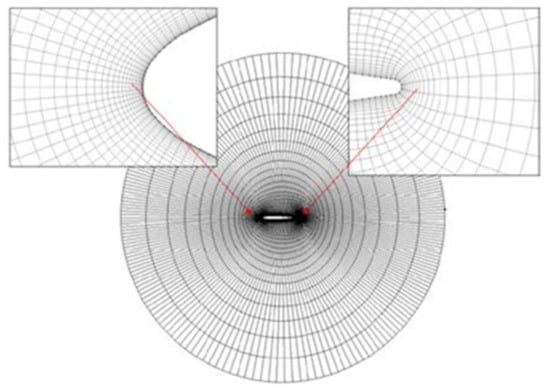
Figure 2.
The O type mesh.
Since the upper and lower rotors of the coaxial double rotor are very close, generally less than 0.1D, the lower rotor is in the downwash flow field of the upper rotor, and the aerodynamic interference between the upper and lower rotors is very strong. The body-fitted structured foreground grid of the upper and lower rotor blades cannot pass through each other’s blade surface, so the outer boundary of the foreground grid of the upper and lower rotor blades is smaller than 0.1R. The foreground grid area and the background grid area are divided into smaller grid sizes to ensure an effective nesting relationship between the foreground and background grids. The background grid area corresponding to the middle region of the coaxial double rotor is locally clustered. The coaxial dual-rotor structure motion nested grid system is shown in Figure 3.
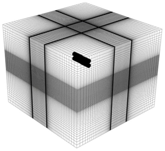
Figure 3.
Coaxial dual-rotor structure motion nested grid system.
In this paper, a polyhedron nested grid method is used for the simulations. The foreground grid includes propeller region mesh and paddle area mesh, which is moving with time; the background grid is a fluid domain grid containing the entire composite coaxial helicopter structure, which is always stationary.
Since there are many irregularities in the background grid area, it is not suitable for the use of structured grids. Therefore, the entire flow field of a compound coaxial helicopter was generated by commercial software to produce a Cartesian grid system which is similar to the structured grid. Region, swept by the foreground grid, is partly clustered to ensure the background mesh and the foreground mesh boundary size equal, which achieve the foreground grid and background grid nested. The fuselage, the landing gear, the wing and the tail field boundary is made with a grid refinement process to ensure higher computing accuracy. Compound coaxial helicopter motion nested mesh system assembly diagram is shown in Figure 4.
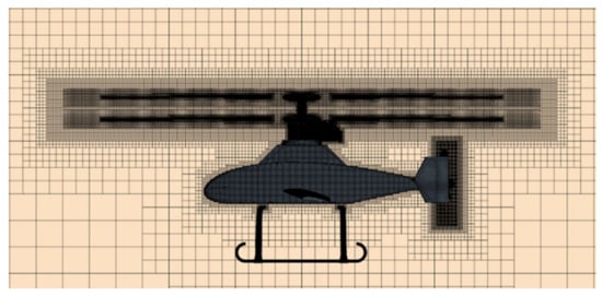
Figure 4.
Compound coaxial helicopter motion nested mesh system assembly diagram.
The basic dimensions of the background grid, the blade grid, and the propeller grid are 0.25 m, 0.01 m, and 0.005 m, respectively. The rest of the grids are refined on the basic dimensions to generate a reference grid. In addition to the reference grid (grid C) with 13,659,192 cells, two coarser grids were constructed, consisting of 6,819,093 (grid B) and 3,402,798 cells (grid A). The grids were obtained by coarsening the reference(fine) grid with twice about a factor of 2. The results of the rotor thrust coefficients calculated with the three grids are shown in Figure 5. The results show that the reference (fine) grid is suitable. The difference in the rotor thrust coefficients is about 0.5% between the fine grid and grid B, while it is 7.5% between the reference fine grid and grid A.
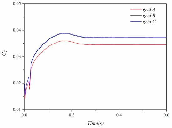
Figure 5.
Rotor thrust coefficients with different grids.
3. Validation of CFD Simulation Method
In order to validate the CFD simulation method proposed in this paper, numerical simulations are carried out on the hovering and forward flight conditions of the NASA coaxial rotor, respectively. The calculated results are compared with the experimental data [39].
3.1. NASA Coaxial Rotor in Hover
In this section, the experimental model of the NASA coaxial rotor is taken as an example to validate the accuracy of numerical simulation in the hovering flight. The detailed parameters of the NASA coaxial rotor are shown in Table 1.

Table 1.
Detailed parameters of NASA coaxial rotor.
The four different tests in the experimental data were studied in this paper. The upper and lower rotor rotation speed is , the collective pitch angles of the upper and lower rotors respectively. The total thrust coefficients and torque coefficients of the upper and lower rotor system in each flight are calculated, respectively, and compared with the experimental data. The calculation results are shown in Figure 6:
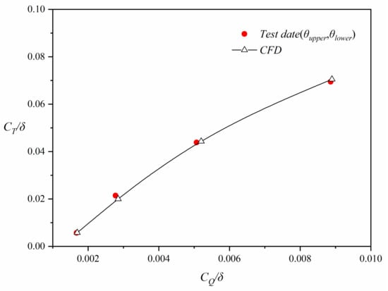
Figure 6.
Coaxial rotor total and in hover flights.
Figure 6 shows that the calculated values are in good agreement with the experimental date, and the error is within . This confirms that the CFD simulation method and grid method proposed in this paper are suitable for the simulation of the interference flow field of the coaxial rotor hovering flight, and can achieve high calculation accuracy.
3.2. NASA Coaxial Rotor in Forward
The model in the hovering flight is used to validate the accuracy of numerical simulation in the forward flight. The distance between the upper and lower rotors is adjusted to 0.24 m. The forward ratio is 0.08, the collective pitch angle of the upper and lower rotors is respectively. The thrust coefficients and torque coefficients of the upper and lower rotor system in each flight are calculated, respectively, and compared with the experimental results. The computed results are shown in Figure 7 and Figure 8.
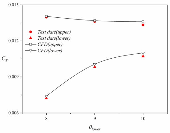
Figure 7.
of the upper and lower rotors in forward flights.
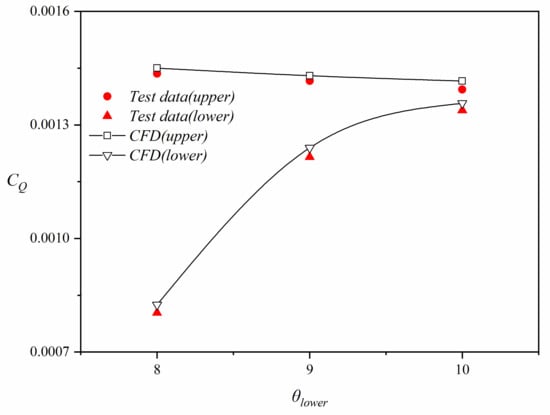
Figure 8.
of the upper and lower rotors in forward flights.
Figure 7 and Figure 8 show the comparison between the computed and experimental results for the thrust coefficients and torque coefficients of the upper and lower rotor system in each flight. It can be seen from this figure that the and on the upper and lower rotor system obtained by the CFD simulations are in good agreement with the experimental data.
4. Results and Discussion
The detailed parameters of the compound coaxial rotor used for CFD simulations in this paper are shown in Table 2. Figure 9 shows the schematic diagram of the compound coaxial helicopter.

Table 2.
Detailed parameters of compound coaxial helicopter rotor.
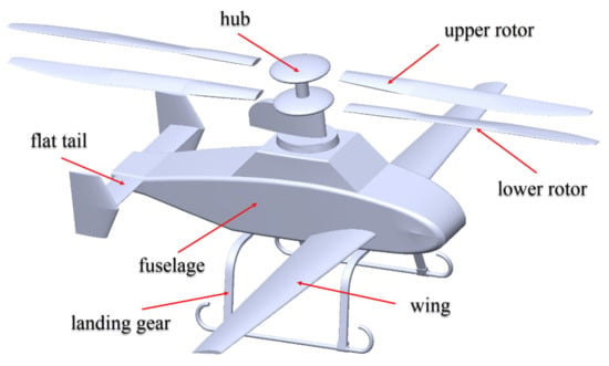
Figure 9.
Schematic diagram of the compound coaxial helicopter.
The aerodynamic performance of the rotor with different overlapping azimuths of blades is calculated. The calculation status of the different rotor overlapping azimuths of the upper and lower blades is shown in Table 3.

Table 3.
Detailed parameters of coaxial helicopter rotor.
State 1 shows an instance when the upper and lower blades are overlapped at 0°(U1) and 180° (U2) for the upper rotor and 180°(L1) and 0° (L2) for the lower rotor or at 90°(U1) and 270° (U2) for the upper rotor and 270°(L1) and 90° (L2) for the lower rotor. State 2 shows an instance when the upper and lower blades are overlapped at 45°(U1) and 225° (U2) for the upper rotor and 225°(L1) and 45° (L2) for the lower rotor or at 135°(U1) and 315° (U2) for the upper rotor and 315°(L1) and 135° (L2) for the lower rotor. where, L1 represents lower rotor blade one, L2 represents lower rotor blade two, U1 represents upper rotor blade one, U2 represents upper rotor blade two.
The simple moving average (SMA), as a tool, is used to smooth the thrust coefficients curve. When new data is available, old data will be deleted, thus resulting in the average to move along the time axis. The reason for this situation is that the monitoring results will fluctuate with the passage of physical time, which requires smoothing processing. This process is achieved by calculating the average of n data points contained in the SMA. By using this method, it will be easier to obtain the calculated results while suppressing the resulting fluctuations. The SMA formula is as follows:
In this case, n is 60.
4.1. Isolated Rotors in Hover
Figure 10, Figure 11 and Figure 12 show the variation of thrust coefficients, torque coefficients, and power loads with time for the isolated rotors in hover. It can be found from Figure 10, Figure 11 and Figure 12 that the rotor thrust coefficients, torque coefficients, and power loads are consistent for state 1 and state 2 in hover, which indicates that the performance of the rotor in the two states is very close.
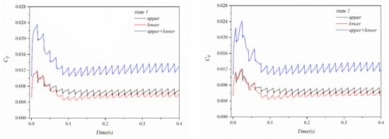
Figure 10.
The isolated rotor of the upper and lower rotors in hover.
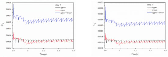
Figure 11.
The isolated rotor of the upper and lower rotors in hover.
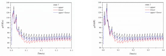
Figure 12.
The isolated rotor of the upper and lower rotors in hover.
Figure 13, Figure 14 and Figure 15 show the comparison of the total thrust coefficients, total torque coefficients, and total power loads during one revolution of the rotor in two states. The relevant data are processed by SMA.
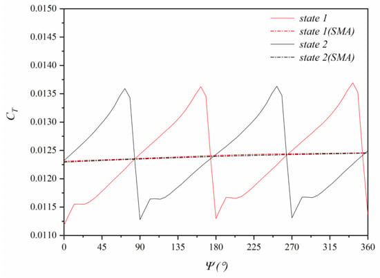
Figure 13.
The isolated rotor in hover.
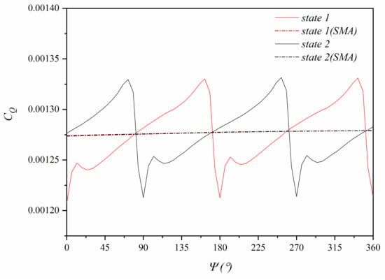
Figure 14.
The isolated rotor in hover.
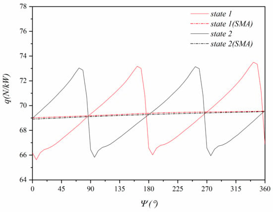
Figure 15.
The isolated rotor in hover.
It can be found from Figure 13, Figure 14 and Figure 15 that the amplitude and peak values of the total thrust coefficients, total torque coefficients, and total power loads for the upper and lower rotors are consistent in the two states, but the phase difference between the two states is . After SMA processing, the total thrust coefficients, total torque coefficients, and total power loads in the two states are also very close, indicating that the rotor overlapping azimuth has little effect on the aerodynamic performance of the isolated rotors in hover.
4.2. Isolated Rotors in Forward
When the helicopter flies at high speed, the tip velocity of the advancing blade reaches the maximum at 90° azimuth, which is easy to produce surge phenomenon, while the tip velocity of the retreating blade reaches the minimum at 270° azimuth, which is easy to produce stall phenomenon. As a result, the overlapping of the upper and lower blades exacerbates the complexity of the flow field and has a negative impact on the aerodynamic performance of the rotor.
Figure 16, Figure 17 and Figure 18 show the variations of thrust coefficients, torque coefficients, and power loads with time for isolated rotors only without fuselage in forward flight. It can be found from Figure 16, Figure 17 and Figure 18 that there is a noticeable difference in the rotor thrust coefficients, torque coefficients, and power loads for state 1 and state 2 in forward.

Figure 16.
The isolated rotor of the upper and lower rotors in forward flight.
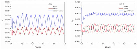
Figure 17.
The isolated rotor of the upper and lower rotors in forward flight.
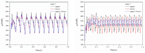
Figure 18.
The isolated rotor q of the upper and lower rotors in forward flight.
For state 1, the phases of the peaks of the thrust coefficients, torque coefficients, and power loads of the upper rotor and the lower rotor are coincident; the total thrust coefficients and torque coefficients of the coaxial double rotor are intensified. As can be seen from Figure 18, the total rotor power loads in state 1 is essentially identical with the power loads of the upper or lower rotor.
However, for state 2, the thrust coefficients of the upper rotor reach a local maximum value and that of the lower rotor reaches a local minimum value; the thrust coefficients of the upper rotor reach a local minimum value and that of the lower rotor reaches a local maximum value. There is a complementary effect between the upper and lower rotor blades so that the fluctuation of the total thrust coefficients, torque coefficients, and power loads of the rotor blades is reduced, which is conducive to improving the flight stability of the coaxial helicopter in forward flight.
In order to quantitatively analyze the aerodynamic performance of the isolated rotors in forward flight under the different rotor overlapping azimuths, the total thrust coefficients, total torque coefficients, and total power loads of the upper and lower rotors in state 1 and state 2 were processed with SMA, as shown in Figure 19, Figure 20 and Figure 21.
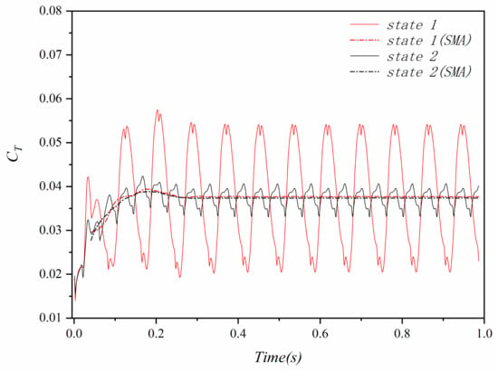
Figure 19.
The isolated rotor in forward flight.
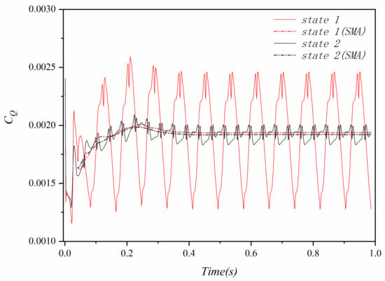
Figure 20.
The isolated rotor in forward flight.
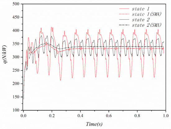
Figure 21.
The isolated rotor in forward flight.
Compared with state 1, in state 2, the total thrust coefficients and the total torque coefficients are reduced by 0.15% and 0.90%, respectively, but the power loads are increased by 3.24%. It shows that although the conventional coaxial double-rotor working at state 1 provides slightly greater thrust than that working at state 2, the former requires greater torque and less power loads.
Compared with state 1, the minimum value of thrust is 61.3% larger, the maximum value of thrust is 24.9% smaller, and the amplitude of thrust fluctuation is 76.3% smaller in state 2. It can be concluded that the overall aerodynamic performance of the coaxial double-rotor working at state 2 is better than that of the rotor working at state 1 in forward flight.
4.3. The Compound Coaxial Helicopter in Hover
The propeller speed of compound coaxial helicopter is 0 RPM in hover. The rotor provides thrust, the wing and the flat tail work in the downwash of the rotor. The downwash flow of the rotor affects the lift of the wing and flat tail. The lift of the wing and flat tail are different in the two states.
The rotor overlapping azimuth has little effect on the aerodynamic performance of isolated rotors in hover. However, the rotors produce different aerodynamic disturbances to the wing and flat tail at different rotor overlapping azimuth. At the same time, the wing and flat tail have a certain impact on the aerodynamic performance of the rotor. Therefore, it is required to study the aerodynamic interference between rotors, wing, and flat tail at different rotor overlapping azimuth in hover on compound coaxial helicopter.
The lift on the wing and flat tail of compound coaxial helicopter in hover is shown in Figure 22 and Figure 23.
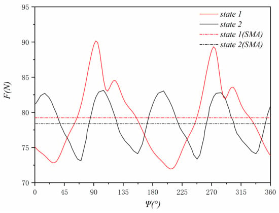
Figure 22.
The lift on the wing in hover.
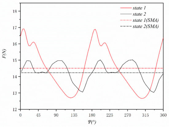
Figure 23.
The lift on the flat tail in hover.
It can be seen from Figure 22 that the maximum value of the lift on the wing in state 2 is 8.1% smaller than that in state 1, while the minimum value is very close. It can be found from Figure 23 that the maximum value of the lift on the flat tail in state 2 is 11.2% smaller than that in state 1, and the minimum value is similar. After SMA processing, compared to state 1, the average lift of the wing and flat tail in state 2 is 1% and 1.7% smaller, respectively. However, compared with state 1, the fluctuation amplitudes of the wing lift and the flat tail lift in state 2 are 42.7% and 52.4% smaller, respectively. The rotor working in state 2 is conducive to reducing the lift fluctuations in the wing and flat tail and improving the stability of the compound coaxial helicopter in hover.
Figure 24, Figure 25 and Figure 26 show the upper rotor thrust coefficients, lower rotor thrust coefficients, and total rotor thrust coefficients of the compound coaxial helicopter in hover.
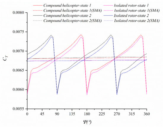
Figure 24.
The compound coaxial helicopter upper rotor in hover.
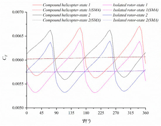
Figure 25.
The compound coaxial helicopter lower rotor in hover.
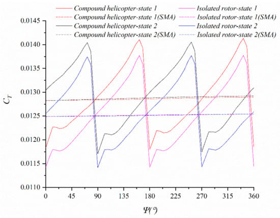
Figure 26.
The compound coaxial helicopter rotor in hover.
It can be seen from Figure 24 that the peak values (maximum value and minimum value) and amplitudes of the upper rotor thrust coefficients of compound coaxial helicopter are close, and the phase difference is in two states. It can be seen from Figure 25 that, compared to state 1, the maximum value of the lower rotor thrust coefficients is 1% smaller, the minimum value is 0.7% smaller, and the amplitude of fluctuations is 2.8% smaller in state 2, but the phase difference between the two states is . It can be seen from Figure 26 that the peak values (maximum value and minimum value) and amplitudes of the total thrust coefficients are close in two states. Due to the different distances between the upper and lower rotors and the fuselage, after SMA processing, the upper rotor‘s thrust coefficients, lower rotor’s thrust coefficients, and total thrust coefficients of the compound coaxial helicopter were 1%, 5%, and 3% larger than that of isolated rotors in hover, respectively. In hover, the difference in rotor thrust coefficients between isolated rotors and compound coaxial helicopter is not obvious.
4.4. The Compound Coaxial Helicopter in Forward
The propeller speed of compound coaxial helicopter in forward flight is 6500 RPM. The forward flight speed of compound coaxial helicopter is 150 km/h. The rotor and wing provide the half lift, respectively, and the thrust is mainly provided by the propeller in forward flight. The downwash flow of the rotor will affect the lift of the wing and flat tail. The lifts of the wing and flat tail are different in the two states. Figure 27 shows the velocity contour of a compound coaxial helicopter in forward flight.
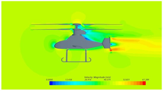
Figure 27.
Velocity contour of a compound coaxial helicopter in forward flight.
The rotor overlapping azimuth has a significant effect on the aerodynamic performance of compound coaxial helicopter in forward flight. The rotors produce aerodynamic interference to the wing. The lift of the wing in forward flight is shown in Figure 28.
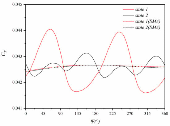
Figure 28.
The wing in forward flight.
As can be seen from Figure 28, compared with state 1, the maximum value of the wing lift coefficients is 2.1% smaller, the minimum value is 1.4% larger, and the amplitude is 61.2% smaller in state 2. After SMA processing, the wing lift coefficients of the two states are identical.
Figure 29, Figure 30 and Figure 31 show the upper rotor thrust coefficients, lower rotor thrust coefficients, and total rotor thrust coefficients of the compound coaxial helicopter in forward flight.
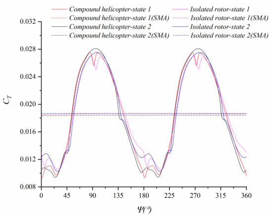
Figure 29.
The compound coaxial helicopter upper rotor in forward flight.
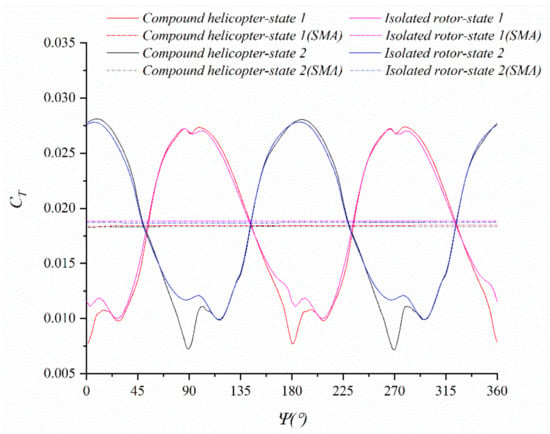
Figure 30.
The compound coaxial helicopter lower rotor in forward flight.
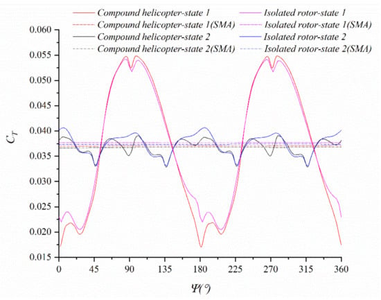
Figure 31.
The compound coaxial helicopter rotor in forward flight.
It can be seen from Figure 29, the thrust coefficients of upper rotors are different at the azimuth of 0 °, 90 °, 180 ° and 270 ° in the two states, but the phase angle of the peak is the same in the two states. It can be seen from Figure 30, the thrust coefficients of lower rotors are different at azimuth 0 °, 90 °, 180 ° and 270 ° in two states. However, the peak’s phase difference of the lower rotor’s thrust coefficients is 90° in the two states.
It can be seen from Figure 31 that in the forward flight of the compound coaxial helicopter, compared with that of state 1, the maximum value of the total thrust coefficients is 28.7% smaller, the minimum value of the total thrust coefficients is 92.8% larger, and the amplitude of total thrust coefficients is 83.5% smaller in state 2. After SMA processing, the total thrust coefficients of state 2 are 0.87% larger than that of state 1. It can be seen that the aerodynamic performance of the compound coaxial helicopter is more stable when the compound coaxial helicopter works in state 2 in forward flight.
5. Conclusions
A computational fluid dynamics (CFD) simulation method is developed and validated to study the influence of rotor overlapping azimuth on compound coaxial helicopter performance. The following conclusions can be drawn:
- (1)
- By comparing the numerical results with the wind tunnel experiment data of the hovering and forward flight of the NASA coaxial rotor, it is found that the numerical simulation results are in good agreement with the experiment data. It is proved that the simulation method proposed in this paper is appropriate for the performance calculation of coaxial helicopters and can achieve high calculation accuracy.
- (2)
- In the hovering flight of isolated rotors, the amplitude and peak values of the total thrust coefficients, and total torque coefficients and total power loads of the upper and lower rotors are essentially identical in the two states, and the phase difference of the coefficients in the two states is . It demonstrates that the aerodynamic performance of isolated rotors is not affected by the rotor overlapping azimuths.
- (3)
- In the forward flight of isolated rotors, the peak of the upper and lower rotor’s thrust coefficients in state 1 has the identical phase, and the phase difference of the peak of the upper and lower rotor’s thrust coefficients in state 2 is . Compared with state 1, the minimum value of the total thrust coefficients is 61.3% larger, the maximum value of the thrust coefficients is 24.9% smaller, and the amplitude of the total thrust coefficients is 76.3% smaller in state 2. After SMA processing, the total thrust coefficients of state 2 are reduced by 0.87% compared to state 1. It can be seen that the aerodynamic performance of isolated rotors in state 2 is superior to that of isolated rotors in state 1 in forward flight.
- (4)
- In the hovering flight of compound coaxial helicopter, the variations of the total thrust coefficients of the rotors in the two states are consistent with the hovering flight of isolated rotors. After SMA processing, due to the interference between the rotor and wing and flat tail, the thrusts of the upper rotor and the lower rotor are 1% and 5% larger than that of isolated rotors in hover, respectively, and the total thrust is 3% larger than that of isolated rotors in hover. Compared with state 1, the minimum value of the wing lift is 0.3% larger, the maximum value is 8.1% smaller, and the amplitude of fluctuation is 42.7% smaller in state 2. Compared with state 1, the minimum value of the flat tail lift is 2.4% larger, the maximum value is 11.3% smaller, and the amplitude of fluctuation is 52.4% smaller in state 2. After SMA processing, compared with that of state 1, the lift of the wing and flat tail in state 2 is reduced by 1% and 1.7%, respectively. It can be found that the aerodynamic performance of the compound coaxial helicopter in hover is more favorable in state 2.
- (5)
- In the forward flight of compound coaxial helicopter, the phase difference between the peak of the thrust in state 2 is between the two rotors. The variations of the total thrust coefficients of the upper and lower rotors in the two states are consistent with the forward flight of isolated rotors. Compared with state 1, the minimum value of total thrust is 92.8% larger, the maximum value is 28.7% smaller, and the amplitude of fluctuation is 83.5% smaller in state 2. After SMA processing, the total thrust coefficients of state 2 were reduced by 0.87% compared with state 1, the upper rotor’s thrust, lower rotor’s thrust, and total thrust are 1.2%, 2%, and 1.65% smaller than isolated rotors in forward flight, respectively. Due to the aerodynamic interference between the rotor and the wing and the flat tail, compared to state 1, the minimum value of wing lift is 1.4% larger, the maximum value is 2.1% smaller, and the amplitude of fluctuation is 61.2% smaller in state 2. After SMA processing, the lift of the wing in state 2 is 0.04% smaller than that of state 1. It can be concluded that the aerodynamic performance of the compound coaxial helicopter working in state 2 is superior to that of the compound coaxial helicopter working in state 1.
- (6)
- At present, the compound coaxial helicopter has become a key point of future high-speed helicopter research, and changing the rotor overlapping azimuth of the upper and lower rotors has a high engineering application value, which can increase aerodynamic stability and reduce lift fluctuations.
Author Contributions
Conceptualization, L.L. and M.C.; methodology, C.Z.; software, L.L.; validation, L.L., C.Z. and A.X.; formal analysis, L.L.; investigation, L.L.; resources, F.W.; data curation, L.L.; writing—original draft preparation, L.L. and C.Z.; writing—review and editing, L.L.; visualization, A.X.; supervision, M.C.; project administration, F.W.; funding acquisition, F.W. All authors have read and agreed to the published version of the manuscript.
Funding
This research was funded by the National Key Research and Development Project of China (No. 2021YFC3002105).
Institutional Review Board Statement
Not applicable.
Informed Consent Statement
Not applicable.
Data Availability Statement
The data presented in this study are available on request from the corresponding author.
Conflicts of Interest
The authors declare no conflict of interest.
References
- Orchard, M.; Newman, S. The fundamental configuration and design of the compound helicopter. Proc. Inst. Mech. Eng. Part G J. Aerosp. Eng. 2003, 217, 297–315. [Google Scholar] [CrossRef]
- Deng, J.H. Development and prospect of helicopter technology. Aeronaut. Sci. Technol. 2021, 32, 10–16. [Google Scholar] [CrossRef]
- Ehinger, R.; McMenemy, M.; Wilson, P. Bell V-280 Valor: JMR TD flight test update. In Proceedings of the Vertical Flight Society’s 75th Annual Forum & Technology Display, Philadelphia, PA, USA, 13–16 May 2019; pp. 1–9. [Google Scholar]
- Yeo, H. Design and aeromechanics investigation of compound helicopters. Aerosp. Sci. Technol. 2019, 88, 158–173. [Google Scholar] [CrossRef]
- Hussain, F.; Kemp, I.; McCarty, P. The future of the military helicopter. RUSI J. 1985, 130, 14–18. [Google Scholar] [CrossRef]
- Yeo, H.; Johnson, W. Performance and Design Investigation of Heavy Lift Tilt-Rotor with Aerodynamic Interference Effects. J. Aircr. 2009, 46, 1231–1239. [Google Scholar] [CrossRef]
- Cheney, M.C. The ABC Helicopter. J. Am. Helicopter Soc. 1969, 14, 10–19. [Google Scholar] [CrossRef]
- Ruddell, A.J. Advancing Blade Concept (ABC™) Development. J. Am. Helicopter Soc. 1977, 22, 13–23. [Google Scholar] [CrossRef]
- Ruddell, A.; Groth, W.; McCutcheon, R. United technologies corp stratford ct sikorsky aircraft div. In Advancing Blade Concept (ABC) Technology Demonstrator; Defense Technical Information Center: Fort Belvoir, VA, USA, 1981. [Google Scholar]
- Li, L.; Chen, M.; Wang, F.; Xu, A. The influence of rotor adjustment parameters on the dynamic balance of a scale-model rigid variable speed rotor. Appl. Sci. 2022, 12, 12125. [Google Scholar] [CrossRef]
- Leishman, J.G. Principles of Helicopter Aerodynamics; Cambridge University Press: New York, NY, USA, 2006; Volume 7–9. [Google Scholar]
- Walsh, D.; Weiner, S.; Arifian, K.; Lawrence, T.; Wilson, M. High Airspeed Testing of the Sikorsky X2 Technology™ Demonstrator. In Proceedings of the American Helicopter Society 67th Annual Forum, Virginia Beach, CA, USA, 3–5 May 2011. [Google Scholar]
- Steijl, R.; Barakos, G.N. Computational Study of Helicopter Rotor-Fuselage Aerodynamic Interactions. AIAA J. 2009, 47, 2143–2157. [Google Scholar] [CrossRef]
- Majhi, J.R.; Ganguli, R. Modeling helicopter rotor blade flapping motion considering nonlinear aerodynamics. Comput. Model. Eng. Sci. 2008, 27, 25–36. [Google Scholar]
- Crouse, G.L.; Leishman, J.G.; Bi, N. Theoretical and Experimental Study of Unsteady Rotor/Body Aerodynamic Interactions. J. Am. Helicopter Soc. 1992, 37, 55–65. [Google Scholar] [CrossRef]
- Zhao, J.; Brigley, M.; Modarres, R.; Welsh, W.A. S-97 Raider Rotor Vibratory Loads Analysis using CFD-CSD. In Proceedings of the AIAA Scitech 2019 Forum, San Diego, CA, USA, 7–11 January 2019. [Google Scholar]
- Ohrle, C.; Frey, F.; Thiemeier, J.; Kessler, M.; Kramer, E.; Embacher, M.; Cranga, P.; Eglin, P. Compound Helicopter X-3 in High-Speed Flight: Correlation of Simulation and Flight Test. J. Am. Helicopter Soc. 2021, 66, 1–14. [Google Scholar] [CrossRef]
- Lorber, P.; Bowles, P.; Fox, E.; Zhe, K.W.; Hein, B.; Mayrides, B. Wind Tunnel Testing for the SB>1 Defiant Joint Multi-Role Technology Demonstrator. In Proceedings of the AHS International 73rd Annual Forum & Technology Display, Fort Worth, TX, USA, 9–11 May 2017; pp. 1–18. [Google Scholar]
- Ruzicka, G.C. Computational fluid dynamics analysis of a coaxial rotor using overset grids. In Proceedings of the AHS Specialist’s Conference on Aeromechanics, San Francisco, CA, USA, 23–25 January 2008. [Google Scholar]
- Berry, J.D.; Bettschart, N. Rotor-fuselage interaction: Analysis and validation with experiment. In Proceedings of the American Helicopter Society Annual Forum, Virginia Beach, VA, USA, 29 April–1 May 1997. [Google Scholar]
- Shibliyev, O.; Sezai, I. Overset Grid Assembler and Flow Solver with Adaptive Spatial Load Balancing. Appl. Sci. 2021, 11, 5132. [Google Scholar] [CrossRef]
- Boyd, J.; Barnwell, D.R.; Gorton, S. A computational model for rotor-fuselage interactional aerodynamics. In Proceedings of the 38th Aerospace Sciences Meeting and Exhibit, Reno, NV, USA, 10–13 January 2000; p. 256. [Google Scholar]
- Bhattacharyya, S.; Conlisk, A. The Structure of the Rotor Wake in Ground Effect. In Proceedings of the 41st Aerospace Sciences Meeting and Exhibit, Reno, NV, USA, 6–9 January 2003. [Google Scholar]
- Sugiura, M.; Tanabe, Y.; Sugawara, H.; Matayoshi, N.; Ishii, H. Numerical Simulations and Measurements of the Helicopter Wake in Ground Effect. Aerosp. Res. Cent. 2017, 54, 209–219. [Google Scholar] [CrossRef]
- Strawn, R.C.; Barth, T.J. A finite-volume Euler solver for computing rotary-wing aerodynamics on unstructured meshes. J. Am. Helicopter Soc. 1993, 38, 61–67. [Google Scholar] [CrossRef]
- Duque, E.; Biswas, R.; Strawn, R. A solution adaptive structured/unstructured overset grid flow solver with applications to helicopter rotor flows. In Proceedings of the 13th Applied Aerodynamics Conference, San Diego, CA, USA, 19–22 June 1995. [Google Scholar]
- Kang, H.J.; Kwon, O.J. Unstructured Mesh Navier-Stokes Calculations of the Flow Field of a Helicopter Rotor in Hover. J. Amer. Helicopter Soc. 2002, 47, 90–99. [Google Scholar] [CrossRef]
- Shenoy, R.; Smith, M.J.; Park, M.A. Unstructured overset mesh adaptation with turbulence modeling for unsteady aerodynamic interactions. Aerosp. Res. Cent. 2014, 51, 161–174. [Google Scholar] [CrossRef]
- Wang, Q.; Zhao, Q.J. Numerical Study on Dynamic-Stall Characteristics of Finite Wing and Rotor. Appl. Sci. 2019, 9, 600. [Google Scholar] [CrossRef]
- Batrakov, A.; Kusyumov, A.; Kusyumov, S.; Mikhailov, S.; Barakos, G.N. Simulation of Tail Boom Vibrations Using Main Rotor-Fuselage Computational Fluid Dynamics (CFD). Appl. Sci. 2017, 7, 918. [Google Scholar] [CrossRef]
- Zhao, Y.Y.; Shi, Y.J.; Xu, G.H. Helicopter Blade-Vortex Interaction Airload and Noise Prediction Using Coupling CFD/VWM Method. Appl. Sci. 2017, 7, 381. [Google Scholar] [CrossRef]
- Deng, J.H.; Fan, F.; Liu, P.A.; Huang, S.L.; Lin, Y.F. Aerodynamic characteristics of rigid coaxial rotor by wind tunnel test and numerical calculation. Chin. J. Aeronaut. 2019, 32, 568–576. [Google Scholar] [CrossRef]
- Zhou, C.; Chen, M. Aerodynamic Simulation of Helicopter Based on Polyhedron Nested Grid Technology. Appl. Sci. 2020, 10, 8304. [Google Scholar] [CrossRef]
- Boisard, R. Numerical analysis of rotor/propeller aerodynamic interactions on a high-speed compound helicopter. J. Am. Helicopter Soc. 2022, 67, 1–15. [Google Scholar] [CrossRef]
- Giljarhus, K.E.T.; Porcarelli, A.; Apeland, J. Investigation of rotor efficiency with varying rotor pitch angle for a coaxial drone. Drones 2022, 6, 91. [Google Scholar] [CrossRef]
- Kim, Y.T.; Park, C.H.; Kim, H.Y. Three-dimensional CFD investigation of performance and interference effect of coaxial propellers. In Proceedings of the 10th IEEE International Conference on Mechanical and Aerospace Engineering (ICMAE), Brussels, Belgium, 22–25 July 2019; IEEE: Piscataway, NJ, USA, 2019; pp. 376–383. [Google Scholar]
- Yoon, S.; Chan, W.M.; Pulliam, T.H. Computations of torque-balanced coaxial rotor flows. In Proceedings of the 55th AIAA Aerospace Sciences Meeting, Grapevine, TX, USA, 9–13 January 2017. [Google Scholar]
- Jameson, A. Time dependent calculations using multigrid, with applications to unsteady flows past airfoils and wings. In Proceedings of the 10th Computational Fluid Dynamics Conference, Honolulu, HI, USA, 24–26 June 1991. [Google Scholar]
- Coleman, C.P. A Survey of Theoretical and Experimental Coaxial Rotor Aerodynamic Research; Ames Research Center: Mountain View, CA, USA, 1997. [Google Scholar]
Disclaimer/Publisher’s Note: The statements, opinions and data contained in all publications are solely those of the individual author(s) and contributor(s) and not of MDPI and/or the editor(s). MDPI and/or the editor(s) disclaim responsibility for any injury to people or property resulting from any ideas, methods, instructions or products referred to in the content. |
© 2023 by the authors. Licensee MDPI, Basel, Switzerland. This article is an open access article distributed under the terms and conditions of the Creative Commons Attribution (CC BY) license (https://creativecommons.org/licenses/by/4.0/).