Communication

Fast Reset Protocol for Superconducting Transmon Qubits

1
Guangdong Provincial Key Laboratory of Quantum Engineering and Quantum Materials, School of Physics and Telecommunication Engineering, South China Normal University, Guangzhou 510006, China
2
Guangdong-Hong Kong Joint Laboratory of Quantum Matter, Frontier Research Institute for Physics, South China Normal University, Guangzhou 510006, China
*
Author to whom correspondence should be addressed.
Appl. Sci. 2023, 13(2), 817; https://doi.org/10.3390/app13020817
Submission received: 28 November 2022 / Revised: 27 December 2022 / Accepted: 28 December 2022 / Published: 6 January 2023
(This article belongs to the Special Issue Superconducting Quantum Computing and Devices)

Abstract

:
For larger-scale quantum information processing, qubit reset plays an important role, as the coherent times for qubits are limited. However, previous schemes require either long reset times or a complex pulse calibration technique, leading to low efficiency in qubit reset. Here, we propose a fast and simple reset protocol for superconducting transmon qubits based on the coupler-coupled qubits architecture. In this setup, a mixing pulse is used to transfer the qubit excitation to the combined excitation of a low-qulity coupler and readout resonator, which will quickly decay to their respectively ground states, leading to efficient qubit reset to the ground state. Our numerical results show that the residual population of the qubit’s excited state can be suppressed to 0.04 % within 28 ns; the reset time will be 283 ns if photon depletion of the readout resonator is required. Thus, our protocol provides a promising way for the high-efficiency superconducting qubit reset.

1. Introduction

As quantum computers can solve some hard problems for classical computing [1,2,3,4,5,6], it has attracted much attention in the last few decades. However, when a quantum computer is running complex and/or large number of operations, it needs the ability to reset qubits to their ground states quickly with high fidelity [7,8,9,10,11]. A simple reset scheme is to passively wait for the qubit naturally dissipate to its ground state [12], and the reset time is longer than the qubit relaxation times ( T 1 ) [13], and thus is not preferable. Subsequently, active qubit reset has been proposed to break through the limitation from T 1 and improve the operational efficiency for qubits [14,15,16,17,18,19,20,21,22]. Recently, some active qubit reset protocols have been demonstrated on many quantum computing platforms.
There are two types of active qubit reset protocols for superconducting circuits; one is the measurement-based reset [14,15,16] and the other one is the non-measurement reset [17,18,19,20,21,22]. In the measurement-based scheme, a qubit can be reset based on measurement results. For instance, if the result is that the qubit is in excited state, a π pulse is added to bring it back to the ground state [14]. However, this method relies heavily on qubit measurement fidelity and low-latency feedback techniques [19]. For the non-measurement scheme, a qubit is coupled to a low-temperature dissipative environment in a controlled way. For superconducting qubits, the dissipation can be naturally provided by a low-quality readout from a superconducting transmission-line resonator.
There are two mainly technical routes for the non-measurement reset of superconducting qubits [17,18,19,20,21,22]. One route is for the frequency-tunable qubit, which can be rapidly tuned into resonance with the low-quality resonator [17,21,22]. However, it requires complex calibration techniques to avoid the influence from the crosstalk on neighboring qubits. Another route is to apply a microwave pulse to induce exchange interaction between the qubit and a low-quality resonator [18,19,20,21]. However, this requires multiple microwave pulses, which complicates its corresponding experiment realizations.
Here, we propose a fast and simple reset scheme for a superconducting qubit based on one of the popular chip designs, i.e., the coupler-coupled-qubits architecture. We first apply a mixing pulse to transfer the excited state of a superconducting qubit to the doubly excited state of a coupler and a readout resonator. Then, the doubly excited state will quickly decay to the ground states of the coupler and a readout resonator, due to their short coherence times compared with the superconducting qubit. That is, we realize fast reset for a superconducting qubit, which is used in a mainstream superconducting qubit chip structure [23,24,25,26,27,28,29,30]. We use the black-box superconducting circuit quantization method [31,32] to analyze the Hamiltonian of the setup, which can transfer the excited state of a superconducting qubit to the doubly excited states of a coupler and a readout resonator. The numerical simulation results show that population of the qubit’s excited state can be suppressed to 0.04 % within 28 ns. Meanwhile, if photon depletion of the readout resonator is required, the reset time will be 283 ns, which is still far shorter than the qubit decay time. Therefore, our scheme provides a promising way for the high-efficiency reset of superconducting qubits, which is necessary for larger scale quantum information processing.

2. Method

Here, we use the black-box superconducting circuit quantization method [31,32] to analyze the Hamiltonian of the setup, the building block of which is shown in Figure 1a. Firstly, the Hamiltonian of the Josephson junction can be described [33] by
H J = 4 E C i n c i 2 E J i cos φ i
where n i and φ i = φ 0 i ( a i + a i ) ( i = c , q ) are the corresponding charge number operator and the phase difference. Under the black-boxing quantization condition [31], it is reasonable to expand the latter in powers of the φ i . Then, we can divide Equation (1) into the nonlinear part and the linear parts. We have
H J = Q n 2 2 C j n + Φ n 2 2 L j n E J n cos φ n + φ n 2 2 ,
where L j n , C j n , Q n and Φ n ( n = c , q ) are equivalent inductance and capacitance from the circuit, and charge and magnetic flux of the Josephson junction, respectively.
Secondly, by decomposing two Josephson junctions in the coupler and qubit, the total circuit now contains only two separated Josephson junctions, seven capacitors and three inductors. To simplify the analysis of the circuit, we use the impedance network method to analyze the circuit—that is, all the capacitances and inductances in the circuit are equivalent to an impedance network Z ( ω ) , as shown in Figure 1b.
Thirdly, in order to transform the phase of the LC circuit into the phase of the junction, the impedance network Z ( ω ) is decomposed into a series of parallel LC resonant electric circuits by using the Foster theorem [34] and the two-port network theory [35], as shown in Figure 1c. The Hamiltonian of the circuit is
H 1 = n = c , q , r Q n 2 2 C n + Φ n 2 2 L n m = c , q E J m cos φ J m + φ J m 2 2 ,
where L n and C n ( n = c , q , r ) are corresponding equivalent inductance and capacitance from the impedance network Z ( ω ) , φ J q = φ c + φ q + φ r and φ J c = k φ J q .
Finally, to perform secondary quantization processing on the parallel LC circuit, we get
n = c , q , r Q n 2 2 C n + Φ n 2 2 L n = n = c , q , r ω n a n a n .
By substituting Equation (4) into Equation (3), the Hamiltonian of the total system can be rewritten as
H 1 = ω c a c a c + ω q a q a q + ω r a r a r E J c cos φ J c + φ J c 2 2 E J q cos φ J q + φ J q 2 2 ,
where E J i are corresponding Josephson energies and φ J i is corresponding superconducting phase difference across the junction. At the same time, φ J q = i = c , q , r φ 0 i ( a i + a i ) and φ J c = k φ J q , where k is the impedance coefficient [31].

3. Results

In this section, we detail our superconducting qubit reset protocol. We firstly reveal the mechanism of our superconducting qubit reset scheme. Then, we introduce the derivation process of the Hamiltonian, which realizes superconducting qubit reset. Finally, we numerically certify our scheme with experimentally reported parameters.

3.1. Summary of the Protocol

The qubit reset scheme is based on the scalable superconducting quantum chip architecture [23,24,25,26,27,28,29,30], where two superconducting qubits are connected to a frequency-tunable coupler, as shown in the Figure 2a. For simplicity, we consider only the circuit model of a single qubit. As sketched in Figure 2b, a frequency-tunable coupler (c) and a readout resonator (r) couple to a superconducting transmon qubit (q) with coupling strengths g c q and g q r , respectively. In general, assuming = 1 , the Hamiltonian of this circuit model is
H 0 = i { c , q , r } ω i a i a i + η c 2 a c a c a c a c + η q 2 a q a q a q a q + g c q a c a q + a c a q + g q r a q a r + a q a r ,
where a i ( a i ) is the corresponding annihilation (creator) operator, ω i is the bare frequency of the corresponding mode and η c and η q are anharmonicity of a coupler and a qubit, respectively.
Based on this circuit model, we introduce how to realize our superconducting qubit scheme. Here, we apply a mixing microwave pulse to the superconducting qubit. With the rotating wave approximation, the driving Hamiltonian is
H d = ϵ ( t ) e i ω d t a q + e i ω d t a q ,
where ω d and ϵ ( t ) are the frequency and the amplitude of the mixing microwave pulse, respectively. For simplicity, we only consider the case where the pulse amplitude is constant—that is, ϵ ( t ) = ϵ . When the frequency ω d meet the condition of ω d = ω c + ω r ω q , the effective Hamiltonian will be in the needed qubit reset form as
H t = G a c a q a r + a c a q a r ,
where G is the coupling strength. For the superconducting qubit in | e state, the state of this system could be transfer | 0 e 0 state to | 1 g 1 state under the action of Equation (8). Finally, the decay (the rate labeled as κ c and κ r ) of the coupler and the readout resonator is used to dissipate the system to | 0 g 0 state, thereby realizing the reset of the superconducting qubit, as described in Figure 2c.

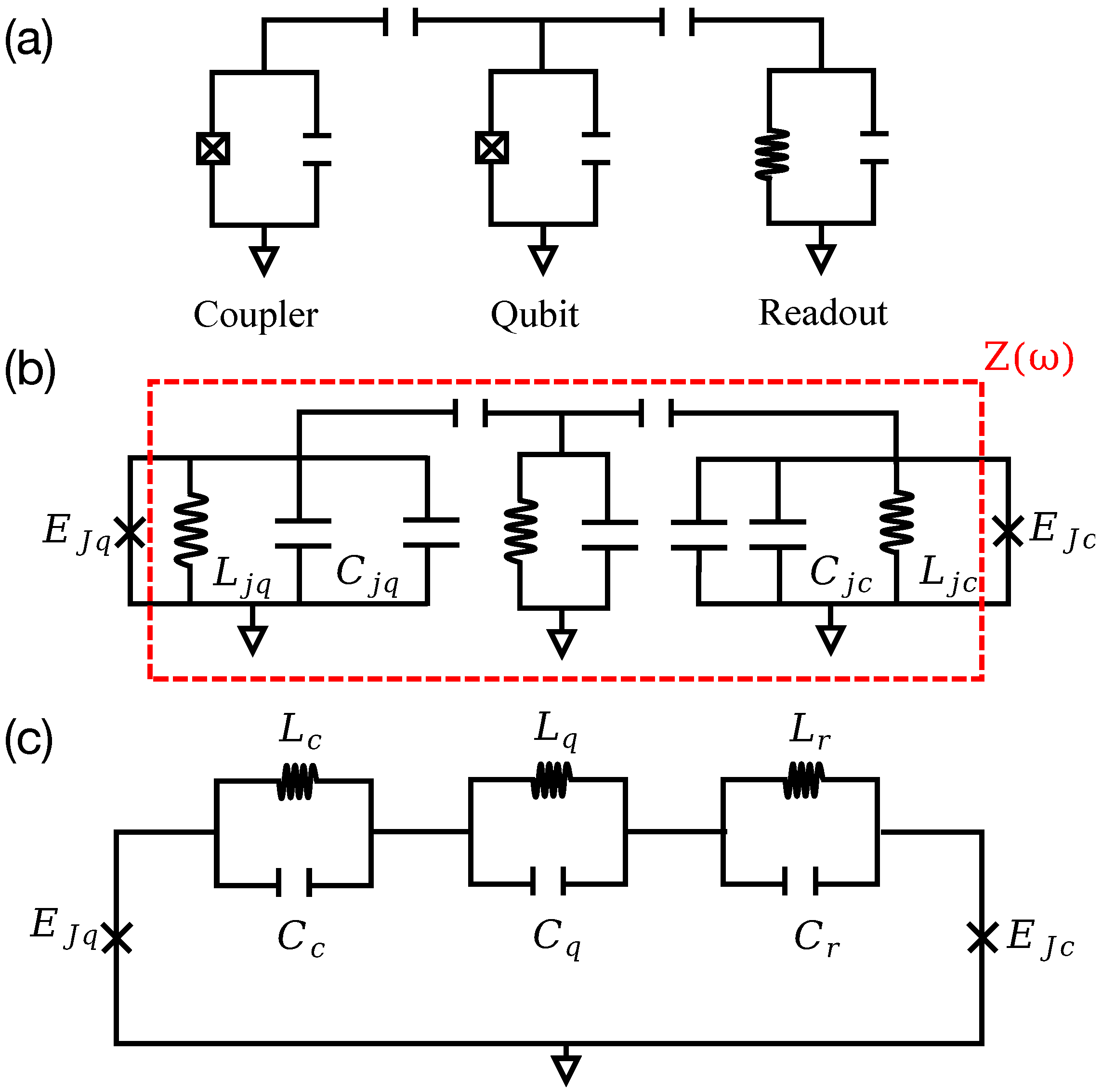
3.2. Quantization of the System

As shown in the above, with a mixing microwave pulse, we can easily realize superconducting qubit reset with the assistant of two decays ( κ c and κ r ). To obtain the effective Hamiltonian Equation (8), we first use the black-boxing quantization method [31,32] to quantize the coupled system, and the quantize Hamiltonian is Equation (5), as shown in the Method Section. Note that, when performing circuit analysis on a superconducting circuits with frequency-tunable couplers that couple qubits, the SQUID-loop [36] of the coupler can be equivalent to the single Josephson junction [37]. Therefore, the circuit in Figure 2b is equivalent to Figure 1a.
In order to produce the desired coupling term, we add a mixing microwave pulse to the system, and the Hamiltonian of the pulse is Equation (7). The Hamiltonian of the system is
H = H 1 + H d .
Then, we use the displacement operator and the picture transformation to simplify the Hamiltonian. Firstly, by displacement unitary, U 1 = exp ( α a q α * a q ) to perform the picture transform for the Hamiltonian of Equation (9). We have
H 2 = i d U 1 d t U 1 + U 1 H U 1 = ω c a c a c + ω r a r a r + i α ˙ a q α ˙ * a q 1 2 | α | ˙ 2 + ω q a q a q α a q + α * a q + | α | 2 E J q cos φ J q 1 + φ J q 1 2 2 E J c cos φ J c 1 + φ J c 1 2 2 + ϵ e i ω d t a q + e i ω d t a q ϵ e i ω d t α + e i ω d t α * ,
where φ J q 1 = φ J q φ 0 q ( α + α * ) , and φ J c 1 = k φ J q 1 . To get the similar form of the Equation (5), we can achieve this goal by selecting the appropriate α . Thus, this parameter α satisfiess two conditions; that is,
i α ˙ a q α ˙ * a q ω q α a q + α * a q + ϵ e i ω d t a q + e i ω d t a q = 0 ,
and ϵ [ exp ( i ω d t ) α + exp ( i ω d t ) α * ] is time independent. By solving the differential equations, we have
α = ϵ Δ e i ω d t ,
where Δ = ω q ω d . Substitute Equation (12) into Equation (10): we get
H 2 = ω c a c a c + ω q a q a q + ω r a r a r E J c cos φ J c 1 + φ J c 1 2 2 E J q cos φ J q 1 + φ J q 1 2 2 .
Apply a transformation with respect to U 2 = exp [ i ( ω q a q a q + ω c a c a c + ω r a r a r ) t ] to Equation (13); we get
H 3 = i d U 2 d t U 2 + U 2 H 2 U 2 = E J q cos φ J q + φ J q 2 2 E J c cos φ J c + φ J c 2 2 ,
where φ J q = i = c , q , r { φ 0 i [ a i exp ( i ω i t ) + a i exp ( i ω i t ) ] } + φ 0 q ( ϵ / Δ ) [ exp ( i ω d t ) + exp ( i ω d t ) ] and φ J c = k φ J q . Then, we expand the cosine term in Equation (14) to the fourth order and remove the constant term. We have
H 3 = E J φ J q 4 4 ! ,
where the E J = E J q + k 4 E J c .
In order to get the three-coupling term of the Hamiltonian intuitively, we could expand the φ J q 4 , remove the constant term and ignore the high-frequency term. Thus, Equation (15) can be written as
H 3 = H t + H n + H s .
The first part is the contribution terms
H t = G a c a q a r e i δ t + a c a q a r e i δ t ,
where G = ( φ 0 q ) 2 ( ϵ / Δ ) φ 0 c φ 0 r E J , and δ = ω q ω c ω r + ω d is the frequency of the coupling term. The second part is the terms which contribute nothing to our reset scheme:
H n = χ c 2 a c a c a c a c χ c r a c a c a r a r χ c q a c a c a q a q χ q r a q a q a r a r ,
where χ c = ( φ o c ) 4 E J / 2 is the self Kerr of the coupler and χ c r = ( φ 0 c φ 0 r ) 2 E J , χ c q = ( φ 0 c φ 0 q ) 2 E J , χ q r = ( φ 0 q φ 0 r ) 2 E J are the dispersive coupling of the corresponding mode. As these coefficients are small quantities relative to G; the effect of these terms is negligible in the Hamiltonian H 3 . The third part is the Stark shift caused by a mixing microwave pulse.
H s = χ s a q a q ,
where χ s = ( φ 0 q ) 4 ( ϵ / Δ ) 2 E J . Due to the shift, the superconducting qubit transition frequency ( ω q ) is approximately at the Stark-shifted superconducting qubit frequency ω q Δ s . This will make the frequency of the mixing microwave pulse not match the frequency in Equation (17), affecting the reset effect of the superconducting qubit. Here, we compensate for the excess frequency Δ s by optimizing the frequency and amplitude of the mixing microwave pulse; that is, ω d = ω c + ω r ω q + Δ s . Thus, the effective Hamiltonian in Equation (17) plays a dominant role in the total Hamiltonian in Equation (16).

3.3. Numerical Simulation

In this subsection, we carry out numerical verification of our reset scheme and analyze the result. Here, we set ω q = 2 π × 5 GHz, ω r = 2 π × 6 GHz, η c = 2 π × 254 MHz, η q = 2 π × 254 MHz [21], κ r 1 = κ c 1 = 50 ns and κ q 1 = 11.5 us. Obviously, there are three variable parameters in the Hamiltonian expressed by Equation (12)—that is, ϵ , ω d and ω c . We also consider the resonant coupling of Equation (13)—that is, δ = 0 . With respect to the resonant condition δ = 0 , we can get ω c as a function of ω d , which is ω c = ω d + ω q ω r . Therefore, we can optimize the effect of superconducting qubit reset by adjusting the amplitude ϵ and frequency ω d of the mixing pulse. We perform a numerical simulation for our superconducting qubit reset scheme by using the Lindblad master equation of
ρ ˙ 1 = i H , ρ 1 + i = c , r , q κ i 2 L | 0 i 1 | + 2 | 1 i 2 |
where ρ 1 is the density matrix of the considered system, L ( A ) = 2 A ρ 1 A A A ρ 1 ρ 1 A A for operator A and κ i is the corresponding decoherence rate.
The residual excitation population of a qubit is an important indicator for measuring the superconducting qubit reset scheme. Here, we optimize the residual excitation population of a qubit by adjusting the amplitude ϵ and frequency ω d of the mixing pulse. By calculating, we have χ s = 2 π × 11.2 MHz and G = 2 π × 23.4 MHz of point A. The frequency Δ s is produced by χ s , which has been canceled by the frequencies ω d of the mixing microwave pulse at optimum point A ( ϵ = 2 π × 240 MHz and ω d = 2 π × 8.2 GHz) of Figure 3a. Therefore, the best effect of the superconducting qubit reset at optimization point A, that is, | 0 e 0 state, can be suppressed to 0.04 %, as shown in Figure 3b. In addition, the qubit reset time is also an important indicator for measuring the superconducting qubit reset scheme. Thus, we numerically simulate the change in the population of the excited states of the qubit with time. As shown in Figure 3b, we show that the | 0 e 0 can be suppressed to 0.04 % within 28 ns (population of the | e decay to first minimum value). Meanwhile, our results show that the residual excitation population of the superconducting qubit can be suppressed to 0.1 % within 283 ns if photon depletion of the readout resonator is required. Therefore, our approach provides a promising way for the highly efficient superconducting qubit reset from the perspective of qubit residual excitation population and reset time.

4. Discussion and Conclusions

We demonstrated a fast and high-fidelity protocol which has the ability to reset a fixed-frequency qubit to 0.04 % in 28 ns without measurement or using a complex pulse. A mixing pulse on the qubit induces the Rabi oscillation between | 0 e 0 and | 1 g 1 , and the state | 1 g 1 can quickly decay to | 0 g 0 due to large k c and k r . This fast and high-efficient reset of the qubit’s excited state has practical significance, as it enhances the execution speed of the quantum algorithm or the quantum simulation based on a scheme with quantum gates. Meanwhile, based on our scheme, the pulse shape can be further optimized to an arbitrary time-dependent form to promote the fidelity of operation, or to keep the first minimum point for a much longer time, which can meet different requirements for various quantum tasks.

Author Contributions

Conceptualization, S.L.; Validation, Z.-C.H.; Investigation, W.-P.Y.; Writing—original draft, W.-P.Y. and S.L.; Writing—review & editing, Z.-Y.X.; Supervision, Z.-Y.X. All authors have read and agreed to the published version of the manuscript.

Funding

This work was supported by the Key-Area Research and Development Program of GuangDong Province (grant number 2018B030326001), the National Natural Science Foundation of China (grant number 12275090), and Guangdong Provincial Key Laboratory (grant number 2020B1212060066).

Institutional Review Board Statement

Not applicable.

Informed Consent Statement

Not applicable.

Data Availability Statement

Not applicable.

Conflicts of Interest

The authors declare no conflict of interest.

References

  1. Shor, P.W. Polynomial-Time Algorithms for Prime Factorization and Discrete Logarithms on a Quantum Computer. SIAM J. Comp. 1997, 26, 1484. [Google Scholar] [CrossRef] [Green Version]
  2. Grover, L.K. Quantum Mechanics Helps in Searching for a Needle in a Haystack. Phys. Rev. Lett. 1997, 79, 325. [Google Scholar] [CrossRef] [Green Version]
  3. Harrow, A.W.; Hassidim, A.; Lloyd, S. Quantum Algorithm for Linear Systems of Equations. Phys. Rev. Lett. 2009, 103, 150502. [Google Scholar] [CrossRef] [PubMed]
  4. Wu, Y.; Bao, W.-S.; Cao, S.; Chen, F.; Chen, M.-C.; Chen, X.; Chung, T.-H.; Deng, H.; Du, Y.; Fan, D.; et al. Strong Quantum Computational Advantage Using a Superconducting Quantum Processor. Phys. Rev. Lett. 2021, 127, 180501. [Google Scholar] [CrossRef]
  5. Bermejo-Vega, J.; Hangleiter, D.; Schwarz, M.; Raussendorf, R.; Eisert, J. Architectures for Quantum Simulation Showing a Quantum Speedup. Phys. Rev. X 2018, 8, 021010. [Google Scholar] [CrossRef] [Green Version]
  6. Huang, H.-Y.; Broughton, M.; Cotler, J.; Chen, S.; Li, J.; Mohseni, M.; Neven, H.; Babbush, R.; Kueng, R.; Preskill, J.; et al. Quantum advantage in learning from experiments. Science 2022, 376, 1182. [Google Scholar] [CrossRef] [PubMed]
  7. DiVincenz, D.P. The Physical Implementation of Quantum Computation. Fortschr. Phys. 2000, 48, 771. [Google Scholar]
  8. Ryan-Anderson, C.; Bohnet, J.; Lee, K.; Gresh, D.; Hankin, A.; Gaebler, J.; Francois, D.; Chernoguzov, A.; Lucchetti, D.; Brown, N.; et al. Realization of Real-Time Fault-Tolerant Quantum Error Correction. Phys. Rev. X 2021, 11, 041058. [Google Scholar] [CrossRef]
  9. Chen, E.H.; Yoder, T.J.; Kim, Y.; Sundaresan, N.; Srinivasan, S.; Li, M.; Córcoles, A.D.; Cross, A.W.; Takita, M. Calibrated Decoders for Experimental Quantum Error Correction. Phys. Rev. Lett. 2022, 128, 110504. [Google Scholar] [CrossRef]
  10. Córcoles, A.D.; Takita, M.; Inoue, K.; Lekuch, S.; Minev, Z.K.; Chow, J.M.; Gambetta, J.M. Exploiting Dynamic Quantum Circuits in a Quantum Algorithm with Superconducting Qubits. Phys. Rev. Lett. 2021, 127, 100501. [Google Scholar] [CrossRef]
  11. Botelho, L.; Glos, A.; Kundu, A.; Miszczak, J.A.; Salehi, O.; Zimborás, Z. Error mitigation for variational quantum algorithms through mid-circuit measurements. Phys. Rev. A 2022, 105, 022441. [Google Scholar] [CrossRef]
  12. Ladd, T.D.; Jelezko, F.; Laflamme, R.; Nakamura, Y.; Monroe, C.; O’Brien, J.L. Quantum computers. Nature 2010, 464, 45. [Google Scholar] [CrossRef] [PubMed] [Green Version]
  13. Wang, C.; Li, X.; Xu, H.; Li, Z.; Wang, J.; Yang, Z.; Mi, Z.; Liang, X.; Su, T.; Yang, C.; et al. Towards practical quantum computers: Transmon qubit with a lifetime approaching 0.5 milliseconds. Npj Quantum Inf. 2022, 8, 3. [Google Scholar] [CrossRef]
  14. Johnson, J.E.; Macklin, C.; Slichter, D.H.; Vijay, R.; Weingarten, E.B.; Clarke, J.; Siddiqi, I. Heralded state preparation in a superconducting qubit. Phys. Rev. Lett. 2012, 109, 050506. [Google Scholar] [CrossRef] [PubMed] [Green Version]
  15. Ristè, D.; Bultink, C.C.; Lehnert, K.W.; DiCarlo, L. Feedback Control of a Solid-State Qubit Using High-Fidelity Projective Measurement. Phys. Rev. Lett. 2012, 109, 240502. [Google Scholar] [CrossRef] [PubMed] [Green Version]
  16. Campagne-Ibarcq, P.; Flurin, E.; Roch, N.; Darson, D.; Morfin, P.; Mirrahimi, M.; Devoret, M.H.; Mallet, F.; Huard, B. Persistent Control of a Superconducting Qubit by Stroboscopic Measurement Feedback. Phys. Rev. X 2013, 3, 021008. [Google Scholar] [CrossRef] [Green Version]
  17. Reed, M.D.; Johnson, B.R.; Houck, A.A.; DiCarlo, L.; Chow, J.M.; Schuster, D.I.; Frunzio, L.; Schoelkopf, R.J. Fast reset and suppressing spontaneous emission of a superconducting qubit. Appl. Phys. Lett. 2010, 96, 203110. [Google Scholar] [CrossRef] [Green Version]
  18. Geerlings, K.; Leghtas, Z.; Pop, I.M.; Shankar, S.; Frunzio, L.; Schoelkopf, R.J.; Mirrahimi, M.; Devoret, M.H. Demonstrating a Driven Reset Protocol for a Superconducting Qubit. Phys. Rev. Lett. 2013, 110, 120501. [Google Scholar] [CrossRef] [Green Version]
  19. Magnard, P.; Kurpiers, P.; Royer, B.; Walter, T.; Besse, J.-C.; Gasparinetti, S.; Pechal, M.; Heinsoo, J.; Storz, S.; Blais, A.; et al. Fast and Unconditional All-Microwave Reset of a Superconducting Qubit. Phys. Rev. Lett. 2018, 121, 060502. [Google Scholar] [CrossRef] [Green Version]
  20. Egger, D.J.; Werninghaus, M.; Ganzhorn, M.; Salis, G.; Fuhrer, A.; Mueller, P.; Filipp, S. Pulsed Reset Protocol for Fixed-Frequency Superconducting Qubits. Phys. Rev. Appl. 2018, 10, 044030. [Google Scholar] [CrossRef] [Green Version]
  21. Zho, Y.; Zhang, Z.; Yin, Z.; Huai, S.; Gu, X.; Xu, X.; Allcock, J.; Liu, F.; Xi, G.; Yu, Q.; et al. Rapid and unconditional parametric reset protocol for tunable superconducting qubits. Nat. Commun. 2021, 12, 5924. [Google Scholar] [CrossRef] [PubMed]
  22. McEwen, M.; Kafri, D.; Chen, Z.; Atalaya, J.; Satzinger, K.J.; Quintana, C.; Klimov, P.V.; Sank, D.; Gidney, C.; Fowler, A.G.; et al. Removing leakage-induced correlated errors in superconducting quantum error correction. Nat. Commun. 2021, 12, 1761. [Google Scholar] [CrossRef] [PubMed]
  23. McKay, D.C.; Filipp, S.; Mezzacapo, A.; Magesan, E.; Chow, J.M.; Gambetta, J.M. Universal Gate for Fixed-Frequency Qubits via a Tunable Bus. Phys. Rev. Appl. 2016, 6, 064007. [Google Scholar] [CrossRef] [Green Version]
  24. Roth, M.; Ganzhorn, M.; Moll, N.; Filipp, S.; Salis, G.; Schmidt, S. Analysis of a parametrically driven exchange-type gate and a two-photon excitation gate between superconducting qubits. Phys. Rev. A 2017, 96, 062323. [Google Scholar] [CrossRef] [Green Version]
  25. Didier, N.; Sete, E.A.; da Silva, M.P.; Rigetti, C. Analytical modeling of parametrically modulated transmon qubits. Phys. Rev. A 2018, 97, 022330. [Google Scholar] [CrossRef] [Green Version]
  26. Caldwell, S.A.; Didier, N.; Ryan, C.A.; Sete, E.A.; Hudson, A.; Karalekas, P.; Manenti, R.; da Silva, M.P.; Sinclair, R.; Acala, E.; et al. Parametrically Activated Entangling Gates Using Transmon Qubits. Phys. Rev. Appl. 2018, 10, 034050. [Google Scholar] [CrossRef] [Green Version]
  27. Rasmussen, S.E.; Christensen, K.S.; Zinner, N.T. Controllable two-qubit swapping gate using superconducting circuits. Phys. Rev. B 2019, 99, 134508. [Google Scholar] [CrossRef] [Green Version]
  28. Stehlik, J.; Zajac, D.; Underwood, D.; Phung, T.; Blair, J.; Carnevale, S.; Klaus, D.; Keefe, G.; Carniol, A.; Kumph, M.; et al. Tunable Coupling Architecture for Fixed-Frequency Transmon Superconducting Qubits. Phys. Rev. Lett. 2021, 127, 080505. [Google Scholar] [CrossRef]
  29. Xu, Y.; Chu, J.; Yuan, J.; Qiu, J.; Zhou, Y.; Zhang, L.; Tan, X.; Yu, Y.; Liu, S.; Li, J.; et al. High-Fidelity, High-Scalability Two-Qubit Gate Scheme for Superconducting Qubits. Phys. Rev. Lett. 2020, 125, 240503. [Google Scholar] [CrossRef]
  30. Ni, Z.C.; Li, S.; Zhang, L.; Chu, J.; Niu, J.; Yan, T.; Deng, X.; Hu, L.; Li, J.; Zhong, Y.; et al. Scalable Method for Eliminating Residual ZZ Interaction between Superconducting Qubits. Phys. Rev. Lett. 2022, 129, 040502. [Google Scholar] [CrossRef]
  31. Nigg, S.E.; Paik, H.; Vlastakis, B.; Kirchmair, G.; Shankar, S.; Frunzio, L.; Devoret, M.H.; Schoelkopf, R.J.; Girvin, S.M. Black-Box Superconducting Circuit Quantization. Phys. Rev. Lett. 2012, 108, 240502. [Google Scholar] [CrossRef] [PubMed]
  32. Gertler, J.M.; Baker, B.; Li, J.; Shirol, S.; Koch, J.; Wang, C. Protecting a bosonic qubit with autonomous quantum error correction. Nature 2021, 590, 243. [Google Scholar] [CrossRef] [PubMed]
  33. Koch, J.; Yu, T.M.; Gambetta, J.; Houck, A.A.; Schuster, D.I.; Majer, J.; Blais, A.; Devoret, M.H.; Girvin, S.M.; Schoelkopf, R.J. Charge-insensitive qubit design derived from the Cooper pair box. Phys. Rev. A 2007, 76, 042319. [Google Scholar] [CrossRef] [Green Version]
  34. Foster, R.M. A Reactance Theorem. Bell Syst. Tech. J. 1924, 3, 260. [Google Scholar] [CrossRef]
  35. Aurell, C. Some Tools for the Analysis and Representation of Linear Two-Port Networks. IEEE Trans. Circuit Theory 1965, 12, 18. [Google Scholar] [CrossRef]
  36. Buks, E.; Blencowe, M.P. Decoherence and recoherence in a vibrating rf SQUID. Phys. Rev. B 2006, 74, 174504. [Google Scholar] [CrossRef] [Green Version]
  37. Krantz, P.; Kjaergaard, M.; Yan, F.; Orlando, T.P.; Gustavsson, S.; Oliver, W.D. A Quantum Engineer’s Guide to Superconducting Qubits. Appl. Phys. Rev. 2019, 6, 021318. [Google Scholar] [CrossRef]
Figure 1. (a) Simplified system diagram of the frequency-tunable coupler. (b) All capacitors and inductors in the circuit form an impedance network Z ( ω ) . (c) The impedance network Z ( ω ) is decomposed into three series LC circuits by the Foster theorem and the two-port network theory.
Applsci 13 00817 g001
Figure 2. (a) The circuit diagrams of system model. Two-dimensional arrangement structure of the qubits and coupler and (b) circuit structure of specific system model. (c) Energy-level diagram of the qubit reset process. The coupling strength between | 0 e 0 and | 1 g 1 states is G; and κ r and κ c denote the decay rates of readout resonator and coupler, respectively. Under the action of κ r and κ c , the | 1 g 1 state can rapidly decay to | 0 g 0 state.
Applsci 13 00817 g002
Figure 3. (a) Two-dimensional scan of the | 0 e 0 population by adjusting the amplitude ( ϵ ) and the frequency ( ω d ) of the mixing pulse. (b) Time evolution of the qubit excited state population, after parametric optimization corresponding to the point A, with ϵ = 2 π × 240 MHz and ω d = 2 π × 8.2 GHz. At 28 ns, the population of the | 0 e 0 decays to the first minimum value 0.04 % and remains below 0.1 % after 283 ns.
Applsci 13 00817 g003
Disclaimer/Publisher’s Note: The statements, opinions and data contained in all publications are solely those of the individual author(s) and contributor(s) and not of MDPI and/or the editor(s). MDPI and/or the editor(s) disclaim responsibility for any injury to people or property resulting from any ideas, methods, instructions or products referred to in the content.

