1. Introduction
In the past decade, statistics data indicate that an average of one hundred satellites were launched annually. Most of them accomplished their missions without substantial impediments. Nevertheless, a small number of them experienced irregularities and even failures of varying severity [
1]. Launcher failure was the most typical reason for failure in the past. In recent years, however, on-orbit failures have, for the first-time, overtaken launch failures [
2], resulting in cumulative billions of dollars in damages [
3]. In addition, all launched satellites eventually run out of fuel, necessitating their retirement [
4]. Several investigations [
5,
6,
7] have shown that repairing damaged spacecraft in flight is cost-effective, and Sale et al. [
8,
9] have given a model that integrates risk and uncertainty analysis. NASA realized as early as the 1980s [
10] the significance of robotics in orbit servicing activities to protect their assets in space. On-orbit servicing (OOS) involves the maintenance of deployed space systems in orbit, including the repair, assembling, refueling, and/or upgrading of spacecraft. Notably, such difficult space missions have spurred the development of novel space robotics technologies and a number of manned and unmanned experimental demonstration missions [
10]. A typical space robotic system (sometimes referred to as a space manipulator or space robot) for an OOS mission is comprised of the following three key components: The servicing system consists of a base spacecraft or servicing satellite, an n-DOF robot manipulator coupled to the servicing satellite, and a target spacecraft to be serviced. ‘Servicing system’ is also used to describe a vehicle designed to service the manipulators of spacecraft. Since the inaugural deployment of the Shuttle Remote Manipulator System (SRMS) from the Space Shuttle Columbia’s cargo area in 1981, numerous space missions, including the International Space Station (ISS), have included robotic systems [
11]. SRMS is a 15.2 m long, six-degrees-of-freedom (DOF) robotic manipulator known as Canadarm that was developed by the Canadian Space Agency (CSA) and has performed multiple on-orbit servicing missions [
12].
As a result of advancements in robotics technology, some of today’s space manipulators can move with incredible dexterity, allowing them to help or even replace astronauts in completing precise, complex, or potentially hazardous jobs. Multiple experimental space manipulators, for instance, have been tested successfully in space. Later, DLR devised the robotics experiment ROKVISS (Robotics Component Verification on the International Space Station) [
13]. NASA and General Motors constructed the second Robonaut, R2, for flight testing aboard the International Space Station. This advanced, agile, humanoid robot offers significant technical advances over its predecessor, making it a far more valuable tool for astronauts. Increases in force sensing, range of motion, bandwidth, and dexterity are among the enhancements [
14].
Therefore, the development of astronaut space robots for space exploration and utilization of space resources is essential for the evolution of space automation technology.
Space robots are one of the most promising alternatives for on-orbit servicing (OOS) operations such as docking, berthing, refueling, repairing, upgrading, transporting, rescuing, and orbital trash cleanup. In the previous two decades, numerous enabling techniques and technology demonstration missions have been created and implemented. There have been a number of successful manned service missions in orbit, but unmanned service missions have not yet been completed.
The investigation of robotic maintenance continues to be a dynamic topic with a variety of technical challenges, and robot mobility is crucial as it enables operations outside of a space station.
LARM
2 laboratory at Tor Vergata University in Rome has previously presented basic feasibility studies to provide indications for a feasible design of a first preliminary prototype [
15,
16,
17] through performance evaluation utilizing kinematics and dynamics simulations, with results demonstrating the feasibility of Torveastro robot operation and its peculiarities to define an appropriate full design. The mobility performance has been characterized using simulations. The operation efficiency and fundamental performance of the arm-leg limb design’s motion have been validated in the laboratory to determine the operation’s viability. In this paper, starting from the first preliminary feasibility studies, a novel optimized version is presented, starting from the geometrical design and going through advanced simulation with realistic input modules lab tests. Therefore, this paper presents the new design, simulation, and tests of a novel advanced Torveastro prototype, a space service astronaut robot for the on-orbit operation requirements of space stations that is able to utilize handrail-equipped installations designed for the movement of human astronauts during outer space operations.
This paper presents the design, simulation, and preliminary tests of novel advanced Torveastro prototype, a space service astronaut robot for the on-orbit operation requirements of space stations that is able to effectively utilize handrail-equipped installations designed for the movement of human astronauts during outer space operations. Torveastro seeks to build a new service robot capable of assisting and substituting astronauts during Extra-Vehicular-Activity (EVA) on orbiting space stations such as the International Space Station. Typical duties for the robot will include monitoring and maintaining the space station’s outer structures. The validation of a terrestrial demonstration prototype is one of the final deliverables of the ongoing project. The project entails the development of innovative limb-like mechanisms and solutions for robot actuators that match the portability and lightness criteria of the space environment.
2. Problems and Requirements
Outer space services for orbital stations can be divided into three categories: assembly, active servicing, and passive servicing. Assembly refers to the creation of structures or components; it entails the merging of minor modules and joints on otherwise monolithic or self-deploying constructions. The space station is intended to be a permanent research facility in orbit. Its primary objective is to conduct world-class science and research in a microgravity environment. The crew of the space station conducts science experiments that require their participation and monitors those that are directed from the ground. However, operating on the space station also necessitates extensive space walks to ensure the station’s maintenance and health.
The space environment continues to be extremely hostile to humans. It is essential to take preventative measures to safeguard the astronaut and the robot in the event of hazardous environmental conditions. Thus, for reasons of safety in space exploration, the astronaut assistant robot plays an increasingly vital role in supporting astronauts to execute their assigned tasks and can also perform some dangerous jobs in their place. In addition, several of these tasks are far more challenging in space than in a training context. One example is the international space station, which is one of humanity’s greatest achievements (ISS). This required a significant technological advancement and, as a result, the activities to be performed in it are complicated, as they are conducted outside the Earth’s atmosphere, in low Earth orbit, and under microgravity. Maintenance, repair, docking, and other tasks to be performed outside the ISS necessitate the support of service robots capable of transporting tools, spare parts, and other equipment required to complete a required task.
Active servicing missions need an astronaut robot to make physical contact with at least one other body, and may include refueling, component repair, and component replacement. Passive servicing missions, on the other hand, do not require physical contact between the space robot and the target object. An astronaut robot that acts as a stiff body without manipulator movement could perform these tasks.
Therefore, large robot mobility is vital, since it ensures work outside of a space station. The astronaut robot is able to move slowly while retaining consistent action outcomes and a strong stance. In addition, environmental factors limit the deployment of service robots in space orbiting stations. The space environment is characterized by microgravity operating on the robot, intense radiation from the sun or other radiation sources, and rapid and drastic temperature fluctuations. Even actuators and electronic equipment may malfunction due to these environmental restrictions.
Microgravity, as described by [
18] at 1 × 10
−6 g, can potentially produce electronical issues besides problems in controlled motion. It is well known that, during the operation of a spacecraft, a complex effect of space circumstances produces issues in automated systems, resulting in a decrease in their orbital service life and, in some cases, failure [
19]. Several authors link equipment problems onboard to solar flares. According to [
19], several onboard studies revealed that multiple electronic failures happened on days without solar flares or magnetic disturbances. Lastly, the experimental setup described in [
19] demonstrated that structural difficulties can develop in any configuration and can cause logic unit switching capabilities to operate abnormally in microgravity. To maintain the reliability of electrical equipment for a range of spacecraft, it is vital to take into account the complicated effect of all space elements, including microgravity [
19].
With the correct laboratory arrangements, planar motion testing or balloon-sustained motions can duplicate the conditions required to imitate microgravity on Earth during investigation and design.
In addition, due to the limited availability of energy sources in orbital stations, energy consumption must be kept to an absolute minimum.
The key to selecting and building a suitable structure for a space service robot, with an emphasis on environment adaptation and motion capabilities, is to attach the aforementioned issues with appropriate design and operation characteristics. In order to select and construct a practical structure for a space service robot, with an emphasis on environment response and locomotion capabilities, the aforementioned features, as well as appropriate design and operation considerations, are needed.
The suggested system will work in one of three modes, allowing for the efficient performance of a variety of activities. In addition to autonomous tasks, the robot may be capable of assisting astronauts with building, maintenance, and monitoring.
3. Methods
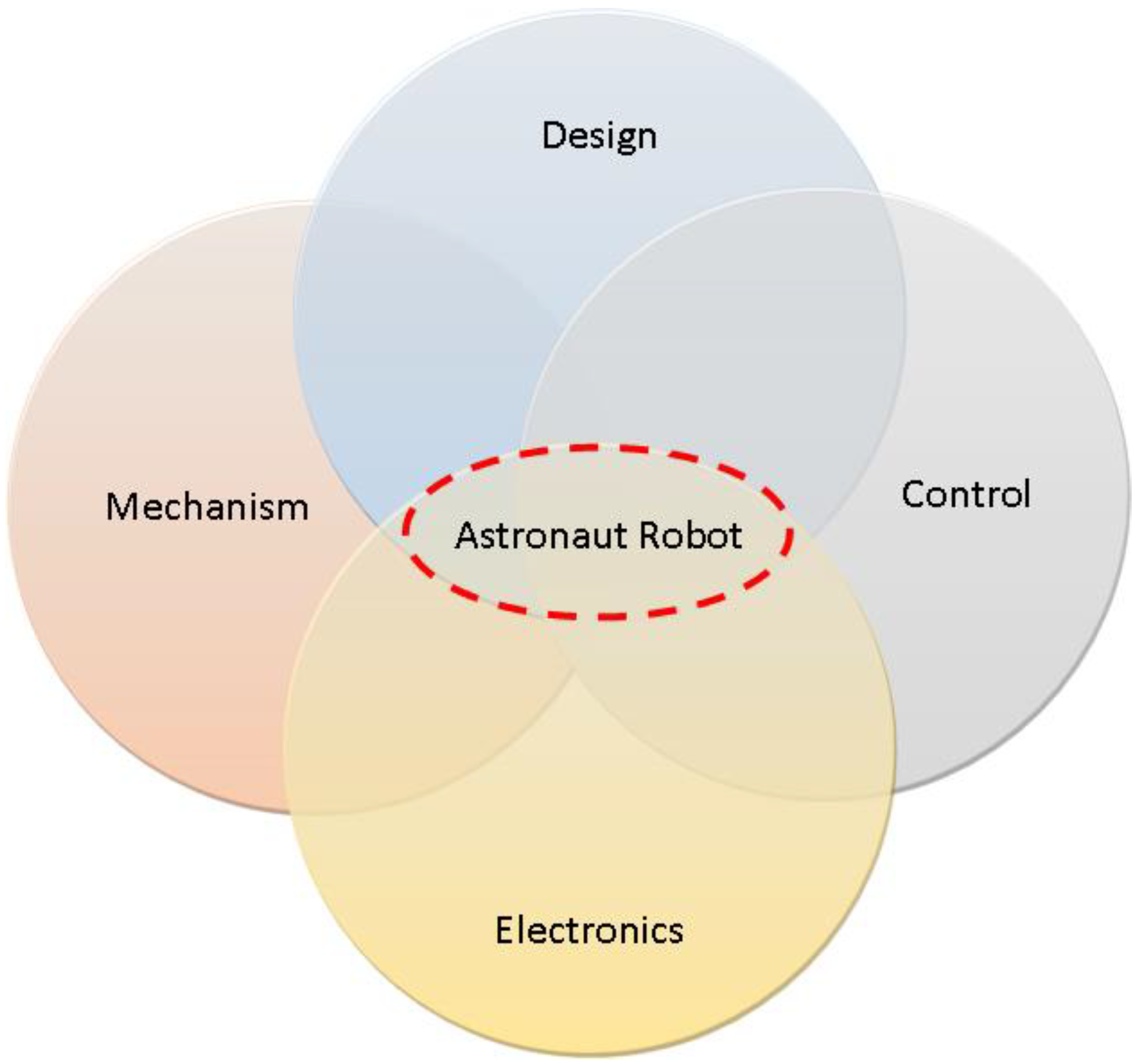
The methods utilized to fulfill the project’s purpose are summarized in
Figure 1. A number of specifications [
20,
21] must be met by an astronaut robot intended for space tasks. The design specifications will correspond to the problem and desired outcomes, such as going from one site to another using existing infrastructure, such as handrails. The mechanism specifications refer to the construction of an appropriate mechanism that can ensure the performance of the astronaut robot for the required task, such as a compliant gripper that can adapt its grabbing while travelling along handrails. The objective of electronics design is to create devices that are compatible with their intended environment and protected from its characteristics, such as ionizing radiation. The ultimate objective of control design is to integrate everything, such as receiving an input and doing the necessary task utilizing embedded sensors. The hostile space environment, consisting of microgravity, complex illumination, and severe radiation, imposes obstacles for space robotics in the areas of long-distance stable mobility, dexterity and safe manipulation, precision sensing, and high-precision measurement [
19].
In a constrained microgravity environment, it is difficult to conduct a variety of stable movements and safe dexterous manipulation, and it is also difficult to verify the 3D motion of a robot astronaut on the ground. However, the motion mechanism of humanoid robots in situations with microgravity differs significantly from that of those on Earth.
Due to advancements in astronaut robot technology, the astronaut robot aboard the space station has improved in terms of stable motion, dexterous manipulation, and precise sensing and measuring.
The aim of the Torveastro project is to create a robot that can work along the current handrails installed outside the space station to aid astronaut movement. Using a combination of bionics and robotics, methods of human-like stable motion were analyzed. The Torveastro robot was therefore built to follow the railings intended for human space travel. Along the surface of the space station, rails are installed to allow astronauts to perform maintenance and service operations in space. To address the issue of hostile space environments, in the Torveastro astronaut robot, all the electronics and actuation are installed in the central body and the forces are transmitted with cables along the limbs, thereby avoiding exposure damage and ensuring long-life performance during inspection, maintenance, and service in-orbit operations.
4. Dimensional Design
In addition to autonomous tasks, an astronaut robot may interact with astronauts on building, maintenance, and monitoring, or aid in these areas. Therefore, significant robot mobility is required, since it ensures that robots can work outside of space stations. The robot can move slowly while retaining consistent action outcomes and a stable posture. Therefore, the Torveastro robot is designed to navigate along the handrails intended for human space travel. Along the surface of the space station, railings are constructed so astronauts may undertake maintenance and service operations in orbit. The handrails feature a small (34.95 × 15.9) mm structure, are highly stable and easy to grip, and are separated by 1 m [
22]. An example of an installation of handrails in space is represented in
Figure 2.
It has been determined that the body of the service robot will be cylindrical and consist of three limbs 120° apart that are equally spaced. Additionally, the limb will feature two links and an end effector. The arc-shaped links in
Figure 3 are intended for a home setup that is suited for launch storage.
Using the data in
Figure 3, it is possible to perform a geometric optimization according to Equations (1)–(3) to find the robot body and link dimensions:
where
c is length of the entire limb;
R is the radius of the body;
are the distance from the connection of the limb to the body;
is the rotation of the body in respect to the horizontal reference frame;
is the distance between the handrails;
is the sum of the cord of the limb link;
is the inclination of the cord of the limb link in respect to the horizontal reference frame.
The horizontal reference frame represents the distance between handrails, with the beginning and terminating points denoting the grasping points. The configuration with the body rotated 120.00 degrees and the arm extended and slanted 25.62 degrees was selected because it reflects the worst case situation in which the robot is navigating between two known locations utilizing handrails.
In addition, L is 500 mm, or half the distance between the handrails, whereas d and f measure 40 mm apiece.
Assuming l′ = c, it is possible to derive the ideal radius of the body R and length of each link of the limb c/2 by solving Equations (1) and (3) with Carnot’s Theorem as expressed in Equation (3). The results indicate that the best body radius is R = 184.78 mm and that the optimal limb link length is c/2 = 199.67 mm. Using these characteristics, a kinematic simulation was performed to compute the mechanism’s workspace, angular velocities, and angular accelerations to evaluate the design’s feasibility and to characterize its performance.
5. A Kinematic Simulation
The approximation of the design values generated from the previous calculations from Equations (1)–(3) yields a body diameter of 370 mm and a link length of 195 mm, resulting in an arm length of 390 mm. As illustrated in
Figure 4, all indicated factors were used to construct a 2D CAD model for kinematic simulation.
The simulation illustrates only one limb during a 10-s closure phase that restores the arms to a launch configuration where they are entirely wrapped around the central body. In
Figure 4a, the motion begins with fully extended limbs. In the second phase of the movements, the limbs are moved at the same pace, with the limb reaching the middle position in
Figure 4b 70 degrees after moving. In the posture depicted in
Figure 4c, the limb remains motionless while the forearms continue to ascend 14 degrees until they make contact with the robot body. In
Figure 4d’s final closing position, only the end-effector rotates 88 degrees to achieve the fully closed launch configuration.
Figure 5 illustrates the computed angular velocities of the arm’s three segments: the arm, the forearm, and the end-effector. During the closing procedure, it is worth observing that the arm travels from second 0.00 to second 3.00 with a maximum velocity of −35.00 deg/s. Continuously spinning from second zero to second ten, the forearm reaches a top speed of −2.10 deg/s. During the last phase of the closing procedure, the end-effector (EE) is triggered between 8.0 and 10.0 s with a maximum velocity of −43.93 degrees per second.
Figure 6 illustrates the computed angular accelerations of the three arm segments. The arm movement presents one step of angular acceleration from second 0.00 to second 1.50 with a maximum value of −45.75 deg/s
2; the second step from second 1.50 to second 3.00 represents deceleration with a maximum value of 46.36 deg/s
2 until stopping, allowing the forearm to continue for a more smooth closure while avoiding body impacts. The linear angular acceleration relates to the constant and uniform behavior displayed by the angular velocities.
As illustrated by the velocity trend, the forearm is in constant motion from second 0.00 to second 10.00. From second 0.00 to second 5.00, the linear angular acceleration is −0.83 deg/s2 to 0.83 deg/s2, and from second 5.00 to second 10.00, the linear deceleration is −0.83 deg/s2 to 0.83 deg/s2. Lastly, between seconds 8.00 and 10.00, when the EE is triggered, its angular acceleration reaches a maximum of 57.00 deg/s2.
The computed kinematic simulation proved that the operation’s intended angular velocities and angular accelerations are realizable with components that are commercially available.
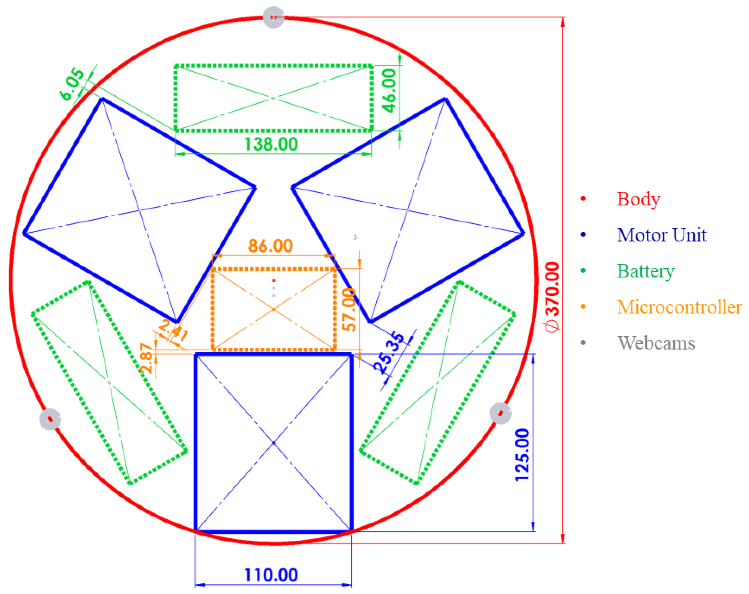
The size and positioning of the three motor units controlling the three degrees of freedom (DoFs) per limb, the control unit, the vision system, and the battery are represented in
Figure 7. The central body protects and houses all electronics, actuators, and controls. When designing the layout, the size of the three commercial Dynamixel MX-64T actuators that will be contained within the motor unit is taken into account. In addition, the size and location of a maximum of three LiPo 14.8 V 6200 mAh batteries utilized for proper operational autonomy have been included. As a microcontroller, a Raspberry Pi 4 will be positioned in the center of the body and connected to three Raspberry cameras. The approximate weight of the designed prototype is 50 N. In conclusion, commercial components have been chosen based on the calculated results to construct a laboratory prototype for testing in a terrestrial gravity field.
6. A Dynamic Simulation
With the dimension’s parameters, a 3D CAD has been created to detail the component of Torveastro that allows it to perform the necessary movement while shielding the actuation, control, and electronics from the elements and keeping the design as compact as possible.
Figure 8 illustrates the finalized Torveastro CAD, while
Figure 8a shows the motor unit in detail. The motor unit, which has three actuators to control the arm’s three DoF, represents the shoulder of Torveastro’s anthropomorphic arm. The motor unit consists of two components. The first component is joined to the frame of the body and includes an actuator; this actuator is directly coupled to the second component, enabling it to spin 360 degrees. The second component of the motor unit has two actuators, one of which moves the cable-driven arm and the other, the cable-driven forearm. Both actuators move the two pulleys by bending and stretching precisely proportionately to the rotational direction.
Figure 8b shows the limbs with their four components. The motor and arm, forearm, and end-effector are connected between each other by proper revolute joints. The motor unit interface permits the attachment of the limb to the motor unit. As previously stated, the arm and forearm are independently manipulated by two cables. The cables are routed via the arm and forearm bodies. A separate motor powers the two-finger end-effector at the end of the body.
Figure 8c shows the prototype’s entire construction. The planned prototype weighs around 50 Newtons. The ABS material from
Table 1 has been selected for the simulations and prototype of Torveastro’s prototype. With the entire CAD model and all of its attributes, an 8-s multibody simulation was performed to simulate a real-world operating scenario and evaluate the feasibility and behavior of the proposed motor unit characteristics.
The results of the simulations are shown in
Figure 9 and in
Figure 10. As shown in
Figure 9a, the shoulder is rotated 180 degrees forward and backward to return to its initial position. In addition, a flexion of the arm was simulated by applying an angular displacement of the corresponding elbow joint through cable actuation, as in
Figure 9b, and a response torque of 2.80 N was applied at the same point to replicate the arm’s total weight of 10 N carrying a payload of 90 N while pulling the cable. In addition, as shown in
Figure 9c, the 100 N payload of the whole arm applied to the motor unit’s edge. In the simulations, both body friction and earth gravity have been taken into account.
Figure 10 shows the simulation results.
Figure 10a displays the angular displacement given as input for shoulder actuation, while
Figure 10b depicts the torque required to achieve the input motion. Between four and eight seconds, the motor starts to move from its initial position of zero degrees, reaches 180 degrees, and then returns to zero degrees.
Figure 10b clearly separates the torque into two components: the component emerging from second 0.00 to 4.00, with a peak torque of 3.13 Nm at second 2.32. At second 4.00, the actuator of the shoulder joint reverses direction to return to the starting position, with the maximum torque of 5.07 Nm being reached at second 6.04. During the descent phase, a larger torque is produced to oppose the terrestrial gravitational pull and maintain the same motion profile. At 4.00 s, the motor that pulls the cable to simulate arm flexion is activated and satisfies the previously defined resistance torque. As seen in
Figure 10c, the actuator needed a maximum torque of 2.80 Nm to accomplish its intended function at second 8.00. As demonstrated in the graphs, the suggested method has a smooth behavior and may be implemented using commercially available intelligent actuators.
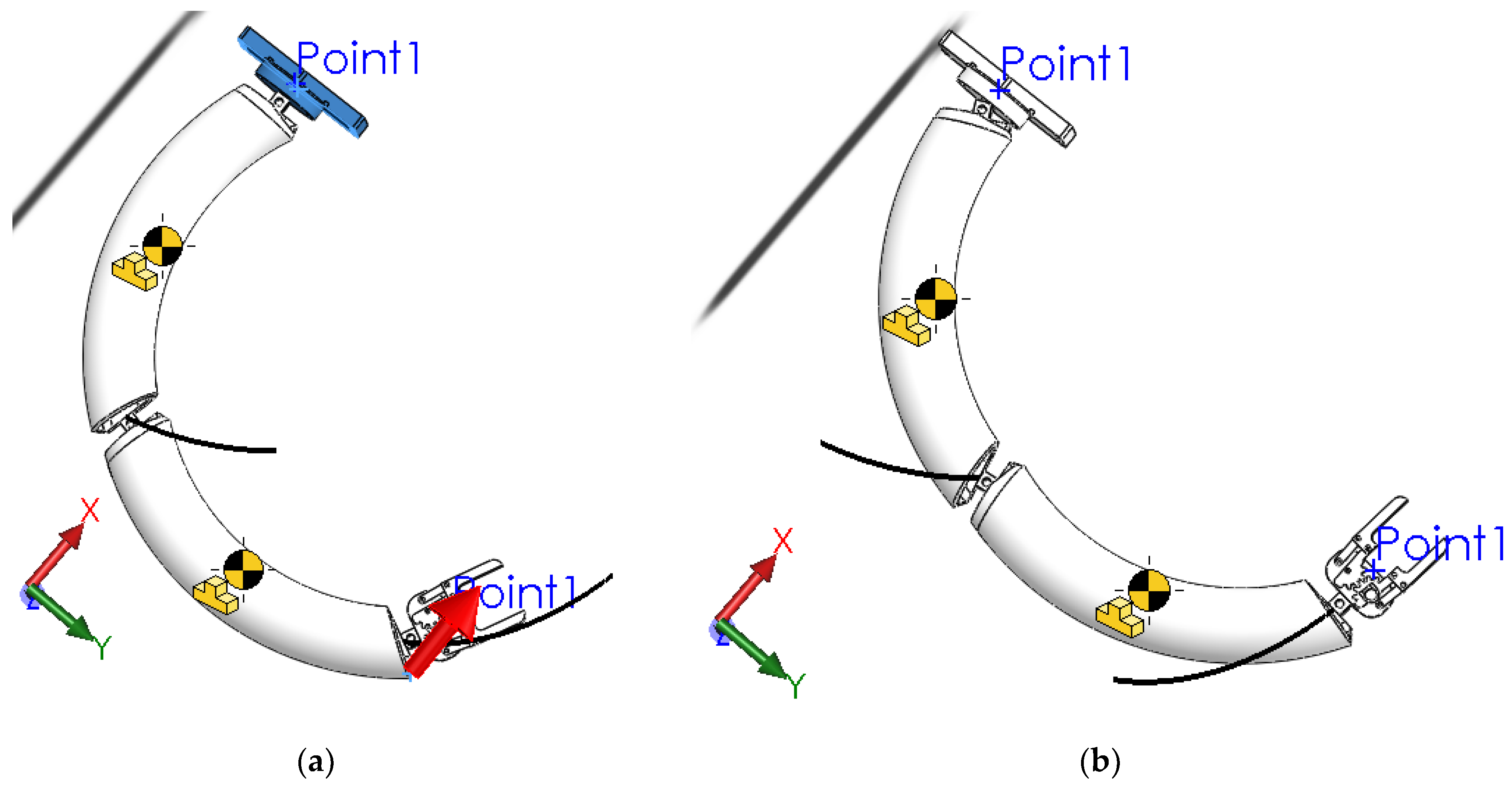
In the following phase, a 5 s displacement input was used to simulate the complete limb. At the end effector, the exact modes and parameters stated before were applied to a 90 N payload.
Figure 11 illustrates the simulation models. As shown by the red arrow in
Figure 11a along the arm’s
X axis, a displacement input for a deflection operation has been given along the
X axis.
Figure 11b displays the end position of the arm as well as its travelled pathways.
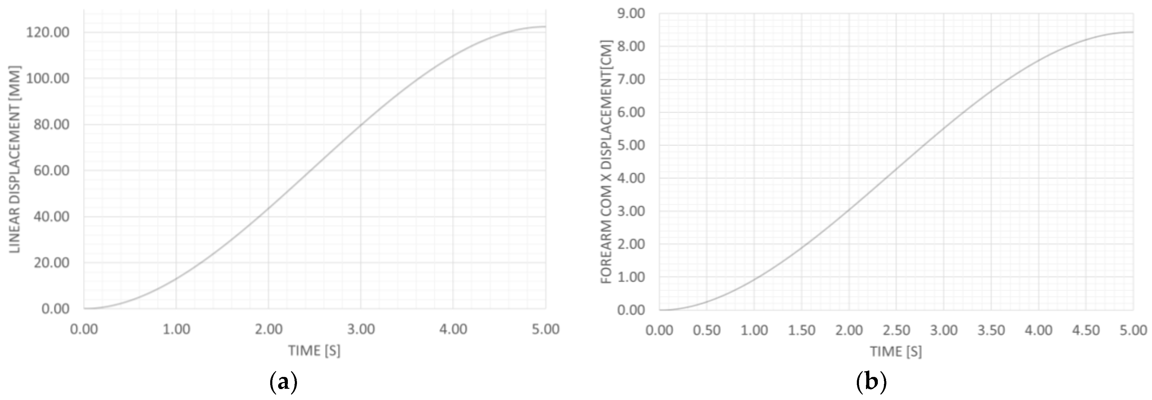
Figure 12 illustrates the results of the simulation.
Figure 12a illustrates the simulation input with a displacement ranging from 0 to 120 mm along the
X axis for 5.00 s based on the trend shown.
Figure 12b illustrates the computed Forearm COM X displacement of 8.44 cm at 5.00 s as a result of the input data.
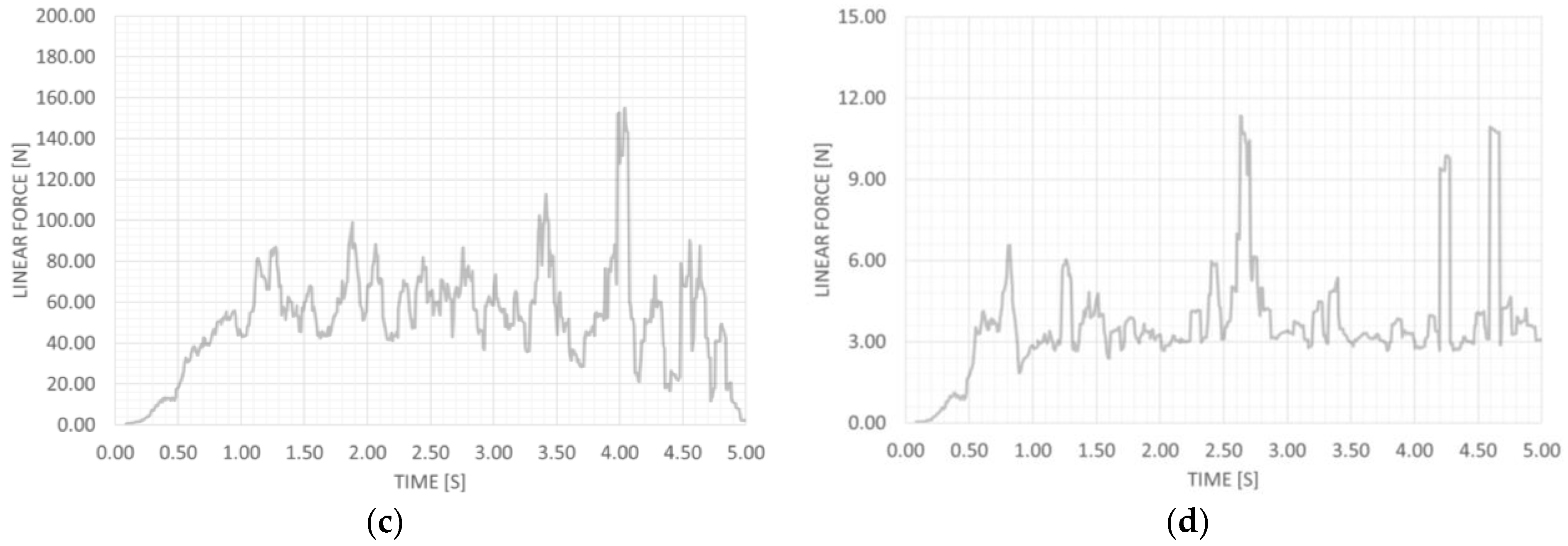
Figure 12c,d illustrate the computed linear force that enabled the subsequent motion.
Figure 12c displays the linear force the arm needed to perform the simulation input, which averaged 50.91 N and peaked at 159.0 N at second 4.10.
Figure 12d depicts the linear force needed by the forearm to execute the simulation input, which averaged 3.63 N and peaked at 11.48 N at second 2.60. For the arm and forearm actuators, the resulting peaks recorded with a 48-mm pulley may be converted into a torque of 3.82 Nm and 1.25 N, respectively. The calculated torques are compatible with the commercial actuators outlined in the preceding section that will be employed in the final prototype.
7. Experimental Tests and Results
Due to their characteristics, Dynamixel MX-64T actuators were chosen based on the results computed from the simulations. A LiPo 14.8 V 6200 mAh battery was supplied for the motor unit for the actuator to achieve the desired performance. A Raspberry Pi 4 was attached to a U2D2 Robotis interface as a microcontroller. Using 3D printing technology, a motor unit was created for preliminary testing. On the motor unit’s fixed part, a Dynamixel MX-64T was placed, and its rotating section was attached to its shaft. In the movable section, a second Dynamixel MX-64T acted as a preliminary load. In order to test the behavior and performance of the designed prototype, the motor controlling the rotation was set to concurrently execute the same simulated motion. To evaluate the experiment’s mobility, a marker was placed on the moving platform, and an external camera tracked the motor unit as it moved.
Figure 13 shows the experimental procedure. The red trajectory and blue angle depict the movements of the platform throw marker as recognized by the Kinovea software.
Figure 14 reports the results of the motion analysis previously described.
Figure 14 depicts the effects of the provided motion, with
Figure 14a depicting the angular displacement and
Figure 14b showing the related angular velocities. Motion began 1.32 s after the recording began. In 5.42 s, the rotating portion turns up to 174.51 degrees. After a 1.37-s delay, the actuators reverse orientation and return to 0.00 degrees 7.90 s later. Two motion steps with opposing velocity directions are shown in
Figure 14b to demonstrate the specified motion. The first section of the angular velocity graph depicts the ascent phase, which peaks at 80.76 at second 1.55. Starting at second 5.42, the section reaches its maximum angular velocity of −94.83 s per second at second 7.78. Comparing simulation results to those of this early testing reveals that simulation outcomes properly represent the simulated environment. Consequently, the suggested solution is viable, and the whole prototype may be built for additional testing.
Using the same hardware to assess a prototype of the limb with a 48 mm pulley, 1.38 degrees of actuator rotation were measured to obtain the same simulated displacement. To monitor the mobility of the experiment, a marker was put on the arm and forearm’s proximal projection of the Center of Mass (CoM), and an external camera caught the movement of the whole arm.
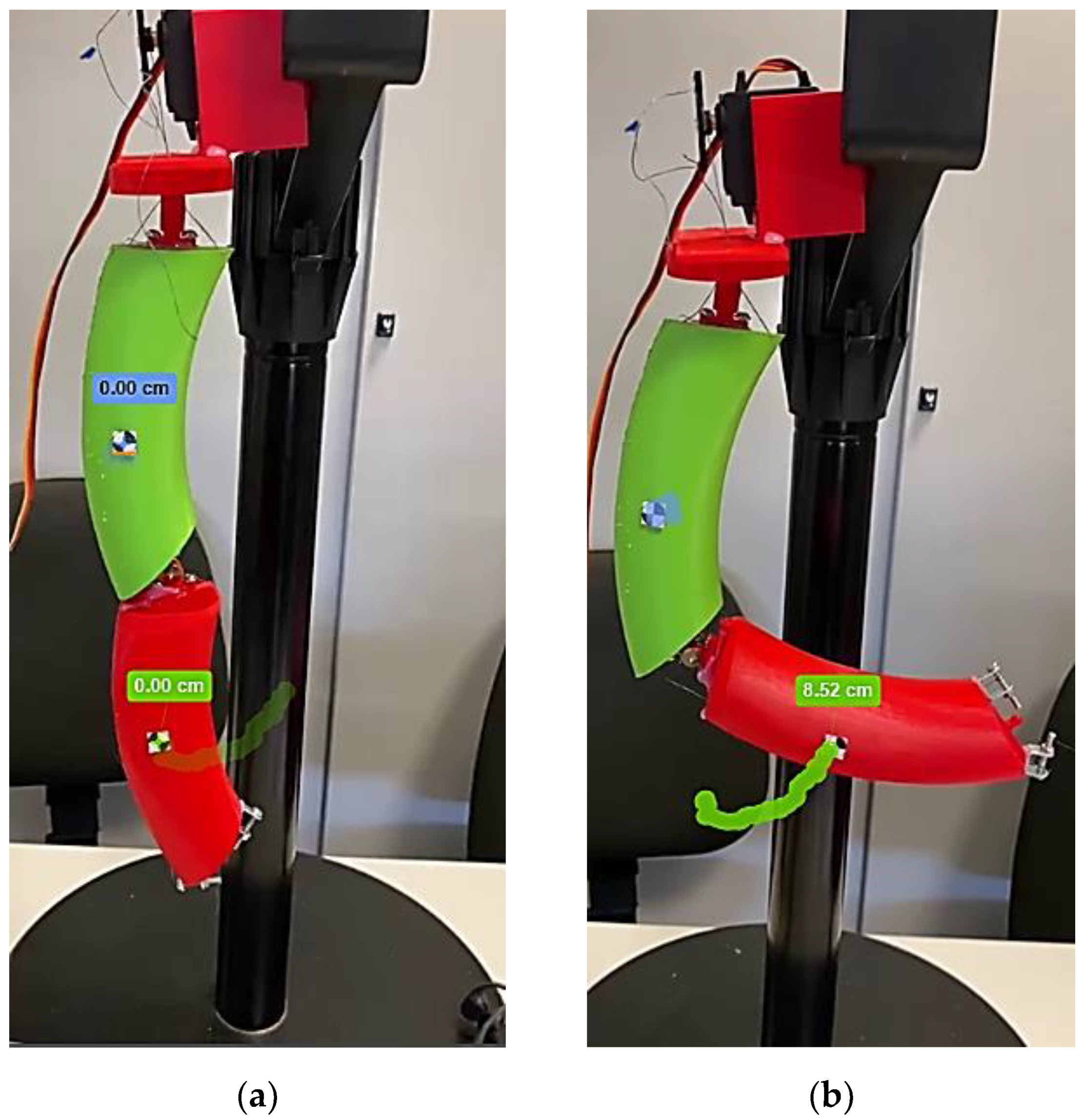
Figure 15 illustrates the experimental method. The blue and green trajectories represent the arm and forearm motions of the markers, as identified by the Kinovea software.
As shown in
Figure 16a, the forearm projected CoM travels a maximum distance of 8.52 cm along the
X axis, perfectly reproducing the simulation results.
Figure 16b displays the related velocities caused by the input motion; the forearm achieves a maximum velocity of 9.45 cm/s at second 1.40 while maintaining an average velocity of 2.36 cm/s. All experimental test results are consistent with the aforementioned prototype simulated design.
In order to simultaneously move the nine actuators of the three limbs of the prototype, a preliminary basic motion control algorithm was developed. The motors were evaluated on the test platform while performing multiple tasks concurrently. As reported in
Figure 17, the entire prototype was manufactured and assembled for the terrestrial motion demonstration whereas the control software was further implemented as duly designed.
The experiments described in the study were conducted utilizing the input needed to complete the fundamental action that the robot will be required to perform. It is essential to note that the robot’s architecture is completely modular, therefore the other motor units and whole arms will behave as demonstrated by the tests, as they are completely independent.
8. Discussion
Multiple sources contribute to the criticism of human space missions. Certain people emphasize the expensive nature of human missions. They contend that the National Aeronautics and Space Administration is overburdened, and that human spaceflight diverts funding from other important tasks. Others deny the scientific relevance of space exploration by humans. Space remains a harsh place for mankind. It is crucial to create preventative procedures to safeguard the astronaut and the robot in the case of those extreme environmental conditions. Thus, for safety concerns in space exploration, an astronaut-helping robot gains more and more importance for supporting astronauts with assigned duties and may even potentially replace people for dangerous operations.
Maintenance, repair, docking, and other duties conducted outside the International Space Station need the employment of service robots capable of transferring tools, replacement parts, and other essential equipment. The major social goal of the Torveastro service astronaut robot is to replace humans for outside chores and for the monitoring and basic maintenance of the space station’s outer structure, therefore decreasing the astronauts’ danger exposure. The remote projection of human capabilities into the Torveastro robot utilizing its teleoperation features may make risk-free field research on orbital stations possible. In telepresence, the motions of a human operator may be communicated electronically to a robot that can imitate them. The visual information provided by the robot’s sensors and cameras may give the human operator the sensation of being physically there throughout the space mission. It is possible to outfit the robot stand-in with greater strength, endurance, and sensory capabilities. Additionally, the Torveastro astronaut robot may highlight the social value of space exploration to the community, hence generating interest in the topic. This may result in more transdisciplinary and international collaboration across many areas, leading to a higher societal effect.
The Torveastro project tackles the”issues of developing a framework for a service robot in orbital station applications by analyzing application-specific requirements in an effort to create a trustworthy, adaptive solution. Torveastro is an astronaut robot with a central body that contains the engines and three equal cable-driven limbs, each fitted with an end-effector capable of clinging to the same handles on the International Space Station for astronauts (and other compatible structures) and employing maintenance equipment.
The mechanical design includes three cable-driven limbs, with each limb comprising a curved shaft arm, a curved shaft forearm, a gripper with two fingers, an actuator for the shoulder joint, an actuator for the arm joint, an actuator for the forearm joint that drives a pulley placed on the elbow with a belt, and an actuator for the gripper. The forearm transmission belt consists of a belt that links the actuator to the elbow pulley and moves within an arm shaft-shaped guide. Therefore, the robot’s resting position needs a modest capacity, which is useful during the launch and inactivity periods. In addition, this design allows the electronics, control, and actuators to be placed inside the core body with sufficient isolation, preventing environmental conditions from causing harm.
Up to now, the design of the Torveastro astronaut robot has centered on the qualities of a low-cost terrestrial demonstration that demonstrates the properties of the proposed Torveasro architecture through the presented simulation results and prototype tests. The proposed kinematic provided the transfer of motion and forces to the joints of the limbs so that the prototype conducted the desired operations. Future advances will focus on the design of an end-effector that can operate as either a gripper or a foot, depending on the job at hand. The investigation will focus on the selection of materials that offer both durability and protection against ionizing radiation and thermal stress. The architecture of the three-tiered control system, which is distinguished hierarchically by the complexity of the activities dedicated to each level, will be the topic of a further key future design. The first (higher) level specifies the more intricate steps necessary to execute a job. The second (intermediate) level analyzes these activities to deconstruct them into reasonably complicated procedures and discovers effective solutions. This level is responsible for computing the parameters of the recognized operations and the relative trajectories to be given to the digital controllers of the servomotors, using the data supplied by the motor sensors and other robot sensors as feedback. The third (lower) level will be responsible for the collection of sensor data, the transmission of instructions to the servomotors of each limb, the management of communication channels between the different hardware components, and any other health-related function.
After the introduced assembly of the first terrestrial demonstrator prototype, the next step will be to validate the general and specific design solutions to achieve a prototype for outer space operations.
9. Conclusions
The design of the service astronaut robot Torveastro for outer space operations was discussed. Using simulations, the practicality of the proposed design was assessed. To evaluate the real-world performance of the proposed structures, a preliminary prototype of the motor unit and the full limb was fabricated, assembled and tested using the same simulation input. A satisfactory comparison between tests and simulations revealed a promising behavior for future advancements. Future endeavors will depend on the simulation of the arm and the whole assembly, as well as their manufacture and testing.
The main features of the suggested innovative solution were summarized as a cable-driven system that is durable (6 h of continuous operation), lightweight (5 kg), scalable, user-oriented, and capable of autonomous or user-controlled assisted remote operation.


